Hot end assembly moving out of print area
Posted by WellTempered
|
Hot end assembly moving out of print area November 20, 2016 06:56PM |
Registered: 7 years ago Posts: 4 |
Hello
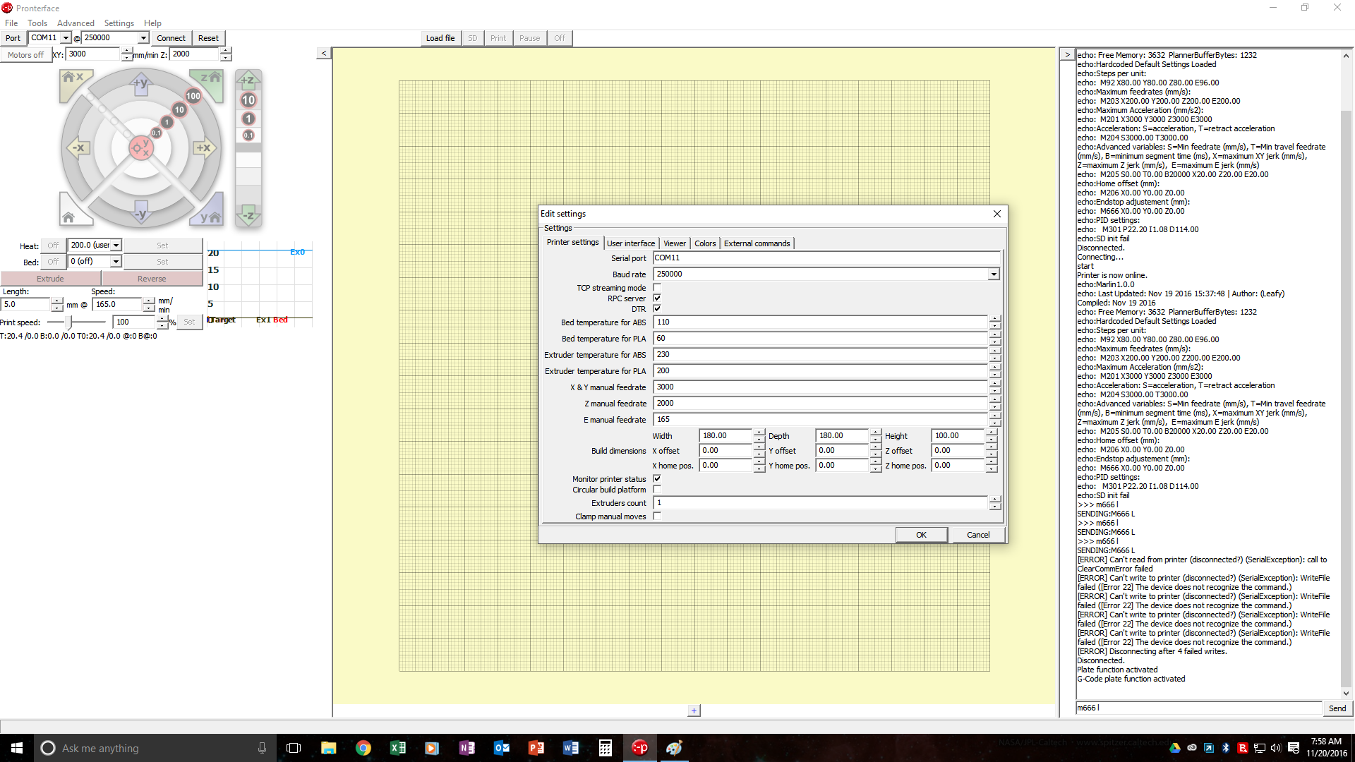
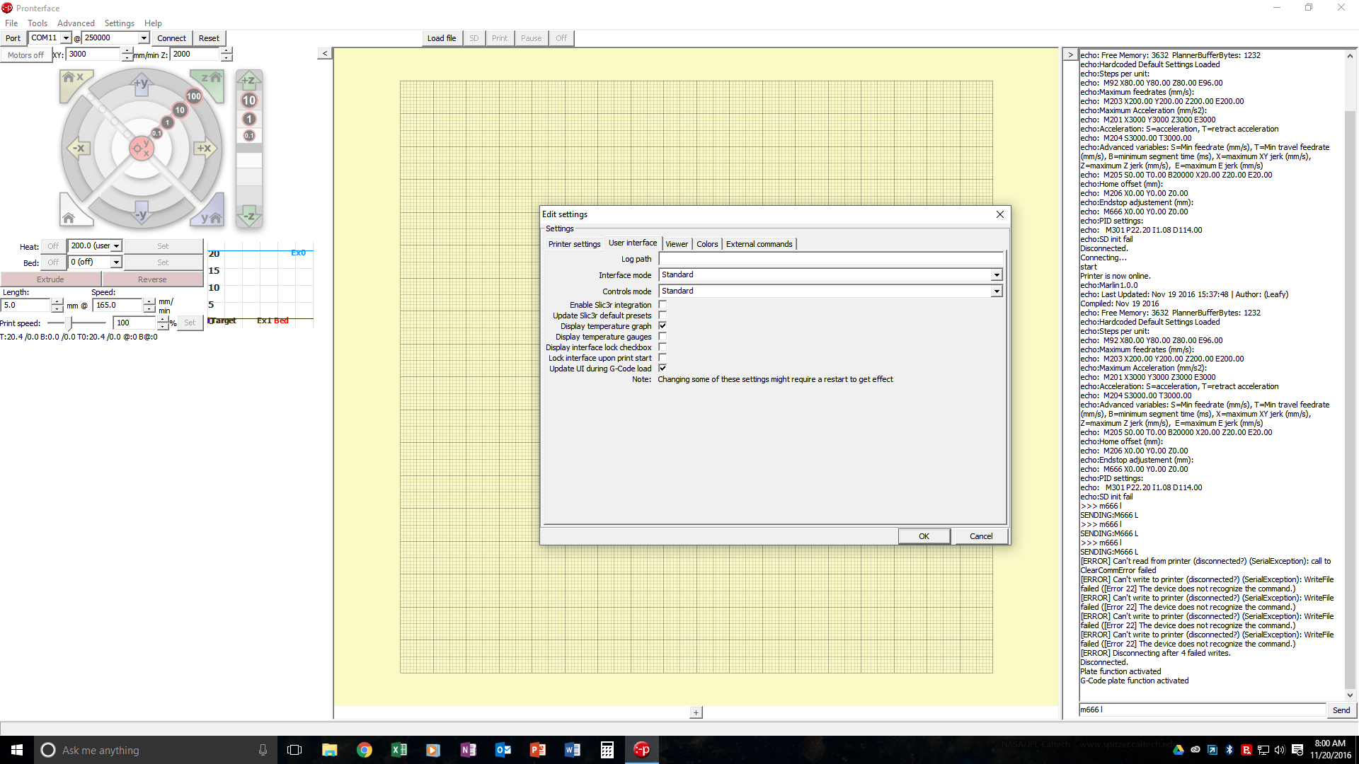
I am new to 3D printing, I purchased the Anycubic Upgraded Pulley Version Unassemble Delta Rostock 3D Printer Kossel Kit Large Print Size from Amazon. I had no issues assembling the kit. I've had issues with the firmware, hence coming here. I have set up the Arduino, Pronterface, and Slic3r with assistance from a friend who has a delta printer but not the same machine. We have gone through the code and are unable to discover the cause. I have a TriGorilla Integrated Main board Compatible Mega2560&RAMPS1.4+5xA4988. I have attached screenshots of Pronterface, and Slic3r settings that seem applicable. Also here is a link to a video of the event. [www.youtube.com]
I had to cut out much of the code for Configuration.h and Configuration_adv.h to make it fit this post. I've never used the formatted code button and wanted to get what seemed to be the important parts up for now. If more of the code is needed please inform me on how the formatted code works and I'll post it. Thanks for any assistance in advance.
//===========================================================================
//============================== 三角洲设置 =============================
//===========================================================================
// Enable DELTA kinematics
#define DELTA
// Make delta curves from many straight lines (linear interpolation).
// This is a trade-off between visible corners (not enough segments)
// and processor overload (too many expensive sqrt calls).
#define DELTA_SEGMENTS_PER_SECOND 160
// Center-to-center distance of the holes in the diagonal push rods.
#define DELTA_DIAGONAL_ROD 217 // mm 碳杆鱼眼中心距
// Horizontal offset from middle of printer to smooth rod center.
#define DELTA_SMOOTH_ROD_OFFSET 151 // mm
// Horizontal offset of the universal joints on the end effector.
#define DELTA_EFFECTOR_OFFSET 31 // mm
// Horizontal offset of the universal joints on the carriages.
#define DELTA_CARRIAGE_OFFSET 20.6 // It was 20.6 // mm Changed Nov 17 2016 JAP
// Horizontal distance bridged by diagonal push rods when effector is centered.
#define DELTA_RADIUS (DELTA_SMOOTH_ROD_OFFSET-DELTA_EFFECTOR_OFFSET-DELTA_CARRIAGE_OFFSET)
// Print surface diameter/2 minus unreachable space (avoid collisions with vertical towers).
#define DELTA_PRINTABLE_RADIUS 90
// Effective X/Y positions of the three vertical towers.
#define SIN_60 0.8660254037844386
#define COS_60 0.5
#define DELTA_TOWER1_X -SIN_60*DELTA_RADIUS // front left tower
#define DELTA_TOWER1_Y -COS_60*DELTA_RADIUS
#define DELTA_TOWER2_X SIN_60*DELTA_RADIUS // front right tower
#define DELTA_TOWER2_Y -COS_60*DELTA_RADIUS
#define DELTA_TOWER3_X 0.0 // back middle tower
#define DELTA_TOWER3_Y DELTA_RADIUS
// Diagonal rod squared
#define DELTA_DIAGONAL_ROD_2 pow(DELTA_DIAGONAL_ROD,2)
//===========================================================================
//============================= 机械方面设置 ===========================
//===========================================================================
// Uncomment the following line to enable CoreXY kinematics
// #define COREXY
// coarse Endstop Settings
#define ENDSTOPPULLUPS // Comment this out (using // at the start of the line) to disable the endstop pullup resistors
#ifndef ENDSTOPPULLUPS
// fine endstop settings: Individual pullups. will be ignored if ENDSTOPPULLUPS is defined
// #define ENDSTOPPULLUP_XMAX
// #define ENDSTOPPULLUP_YMAX
// #define ENDSTOPPULLUP_ZMAX
// #define ENDSTOPPULLUP_XMIN
// #define ENDSTOPPULLUP_YMIN
// #define ENDSTOPPULLUP_ZMIN
#endif
#ifdef ENDSTOPPULLUPS
#define ENDSTOPPULLUP_XMAX
#define ENDSTOPPULLUP_YMAX
#define ENDSTOPPULLUP_ZMAX
#define ENDSTOPPULLUP_XMIN
#define ENDSTOPPULLUP_YMIN
#define ENDSTOPPULLUP_ZMIN
#endif
// The pullups are needed if you directly connect a mechanical endswitch between the signal and ground pins.
const bool X_MIN_ENDSTOP_INVERTING = false; // set to true to invert the logic of the endstop.
const bool Y_MIN_ENDSTOP_INVERTING = false; // set to true to invert the logic of the endstop.
const bool Z_MIN_ENDSTOP_INVERTING = false; // set to true to invert the logic of the endstop.
const bool X_MAX_ENDSTOP_INVERTING = false; // set to true to invert the logic of the endstop.
const bool Y_MAX_ENDSTOP_INVERTING = false; // set to true to invert the logic of the endstop.
const bool Z_MAX_ENDSTOP_INVERTING = false; // set to true to invert the logic of the endstop.
//#define DISABLE_MAX_ENDSTOPS
//#define DISABLE_MIN_ENDSTOPS
// Disable max endstops for compatibility with endstop checking routine
#if defined(COREXY) && !defined(DISABLE_MAX_ENDSTOPS)
#define DISABLE_MAX_ENDSTOPS
#endif
// For Inverting Stepper Enable Pins (Active Low) use 0, Non Inverting (Active High) use 1
#define X_ENABLE_ON 0
#define Y_ENABLE_ON 0
#define Z_ENABLE_ON 0
#define E_ENABLE_ON 0 // For all extruders
// Disables axis when it's not being used.
#define DISABLE_X false
#define DISABLE_Y false
#define DISABLE_Z false
#define DISABLE_E false // For all extruders
#define INVERT_X_DIR true // for Mendel set to false, for Orca set to true
#define INVERT_Y_DIR true // for Mendel set to true, for Orca set to false
#define INVERT_Z_DIR true // for Mendel set to false, for Orca set to true
#define INVERT_E0_DIR true // for direct drive extruder v9 set to true, for geared extruder set to false
#define INVERT_E1_DIR false // for direct drive extruder v9 set to true, for geared extruder set to false
#define INVERT_E2_DIR false // for direct drive extruder v9 set to true, for geared extruder set to false
// ENDSTOP SETTINGS:
// Sets direction of endstops when homing; 1=MAX, -1=MIN
#define X_HOME_DIR 1
#define Y_HOME_DIR 1
#define Z_HOME_DIR 1
#define min_software_endstops false // If true, axis won't move to coordinates less than HOME_POS.
#define max_software_endstops true // If true, axis won't move to coordinates greater than the defined lengths below.
// Travel limits after homing
#define X_MAX_POS DELTA_PRINTABLE_RADIUS
#define X_MIN_POS -DELTA_PRINTABLE_RADIUS
#define Y_MAX_POS DELTA_PRINTABLE_RADIUS
#define Y_MIN_POS -DELTA_PRINTABLE_RADIUS
#define Z_MAX_POS MANUAL_Z_HOME_POS
#define Z_MIN_POS 0
#define X_MAX_LENGTH (X_MAX_POS - X_MIN_POS)
#define Y_MAX_LENGTH (Y_MAX_POS - Y_MIN_POS)
#define Z_MAX_LENGTH (Z_MAX_POS - Z_MIN_POS)
//============================= 自动调平配置 ===========================
#endif
// The position of the homing switches
#define MANUAL_HOME_POSITIONS // If defined, MANUAL_*_HOME_POS below will be used
#define BED_CENTER_AT_0_0 // If defined, the center of the bed is at (X=0, Y=0)
//Manual homing switch locations:
// For deltabots this means top and center of the Cartesian print volume.
#define MANUAL_X_HOME_POS 0
#define MANUAL_Y_HOME_POS 0
#define MANUAL_Z_HOME_POS 332.6 // 打印机归位时,喷嘴到平台的高度。For delta: Distance between nozzle and print surface after homing. Updated 11/20/16 JAP
//// MOVEMENT SETTINGS
#define NUM_AXIS 4 // The axis order in all axis related arrays is X, Y, Z, E
#define HOMING_FEEDRATE {50*60, 50*60, 50*60, 0} // set the homing speeds (mm/min)
// default settings
#define XYZ_FULL_STEPS_PER_ROTATION 200
#define XYZ_MICROSTEPS 16
#define XYZ_BELT_PITCH 2
#define XYZ_PULLEY_TEETH 20
#define XYZ_STEPS (XYZ_FULL_STEPS_PER_ROTATION * XYZ_MICROSTEPS / double(XYZ_BELT_PITCH) / double(XYZ_PULLEY_TEETH))
#define DEFAULT_AXIS_STEPS_PER_UNIT {XYZ_STEPS, XYZ_STEPS, XYZ_STEPS, 96}
#define DEFAULT_MAX_FEEDRATE {200, 200, 200, 200} // (mm/sec)
#define DEFAULT_MAX_ACCELERATION {3000,3000,3000,3000} // X, Y, Z, E maximum start speed for accelerated moves. E default values are good for skeinforge 40+, for older versions raise them a lot.
#define DEFAULT_ACCELERATION 3000 // X, Y, Z and E max acceleration in mm/s^2 for printing moves
#define DEFAULT_RETRACT_ACCELERATION 3000 // X, Y, Z and E max acceleration in mm/s^2 for retracts
// Offset of the extruders (uncomment if using more than one and relying on firmware to position when changing).
// The offset has to be X=0, Y=0 for the extruder 0 hotend (default extruder).
// For the other hotends it is their distance from the extruder 0 hotend.
// #define EXTRUDER_OFFSET_X {0.0, 20.00} // (in mm) for each extruder, offset of the hotend on the X axis
// #define EXTRUDER_OFFSET_Y {0.0, 5.00} // (in mm) for each extruder, offset of the hotend on the Y axis
// The speed change that does not require acceleration (i.e. the software might assume it can be done instantaneously)
#define DEFAULT_XYJERK 20.0 // (mm/sec)
#define DEFAULT_ZJERK 20.0 // (mm/sec)
#define DEFAULT_EJERK 20.0 // (mm/sec)
/*********************************************************************[/color]
* R/C SERVO support
* Sponsored by TrinityLabs, Reworked by codexmas
**********************************************************************/
// Number of servos
//
// If you select a configuration below, this will receive a default value and does not need to be set manually
// set it manually if you have more servos than extruders and wish to manually control some
// leaving it undefined or defining as 0 will disable the servo subsystem
// If unsure, leave commented / disabled
//
//#define NUM_SERVOS 3 // Servo index starts with 0 for M280 command
// Servo Endstops
//
// This allows for servo actuated endstops, primary usage is for the Z Axis to eliminate calibration or bed height changes.
// Use M206 command to correct for switch height offset to actual nozzle height. Store that setting with M500.
//
//#define SERVO_ENDSTOPS {-1, -1, 0} // Servo index for X, Y, Z. Disable with -1
//#define SERVO_ENDSTOP_ANGLES {0,0, 0,0, 70,0} // X,Y,Z Axis Extend and Retract angles
#include "Configuration_adv.h"
#include "thermistortables.h"
#endif //__CONFIGURATION_H
[/quote]
Finally here is my Configuration_adv.h
Quote
#ifndef CONFIGURATION_ADV_H
#define CONFIGURATION_ADV_H
//===========================================================================
//=============================Thermal Settings ============================
//===========================================================================
#ifdef BED_LIMIT_SWITCHING
#define BED_HYSTERESIS 2 //only disable heating if T>target+BED_HYSTERESIS and enable heating if T>target-BED_HYSTERESIS
#endif
#define BED_CHECK_INTERVAL 5000 //ms between checks in bang-bang control
//// Heating sanity check:
// This waits for the watch period in milliseconds whenever an M104 or M109 increases the target temperature
// If the temperature has not increased at the end of that period, the target temperature is set to zero.
// It can be reset with another M104/M109. This check is also only triggered if the target temperature and the current temperature
// differ by at least 2x WATCH_TEMP_INCREASE
//#define WATCH_TEMP_PERIOD 40000 //40 seconds
//#define WATCH_TEMP_INCREASE 10 //Heat up at least 10 degree in 20 seconds
#ifdef PIDTEMP
// this adds an experimental additional term to the heating power, proportional to the extrusion speed.
// if Kc is chosen well, the additional required power due to increased melting should be compensated.
#define PID_ADD_EXTRUSION_RATE
#ifdef PID_ADD_EXTRUSION_RATE
#define DEFAULT_Kc (1) //heating power=Kc*(e_speed)
#endif
#endif
//automatic temperature: The hot end target temperature is calculated by all the buffered lines of gcode.
//The maximum buffered steps/sec of the extruder motor are called "se".
//You enter the autotemp mode by a M109 S T F
// the target temperature is set to mintemp+factor*se[steps/sec] and limited by mintemp and maxtemp
// you exit the value by any M109 without F*
// Also, if the temperature is set to a value
// Mode 0: Full control. The slicer has full control over both x-carriages and can achieve optimal travel results
// as long as it supports dual x-carriages. (M605 S0)
// Mode 1: Auto-park mode. The firmware will automatically park and unpark the x-carriages on tool changes so
// that additional slicer support is not required. (M605 S1)
// Mode 2: Duplication mode. The firmware will transparently make the second x-carriage and extruder copy all
// actions of the first x-carriage. This allows the printer to print 2 arbitrary items at
// once. (2nd extruder x offset and temp offset are set using: M605 S2 [Xnnn] [Rmmm])
// This is the default power-up mode which can be later using M605.
#define DEFAULT_DUAL_X_CARRIAGE_MODE 0
// As the x-carriages are independent we can now account for any relative Z offset
#define EXTRUDER1_Z_OFFSET 0.0 // z offset relative to extruder 0
// Default settings in "Auto-park Mode"
#define TOOLCHANGE_PARK_ZLIFT 0.2 // the distance to raise Z axis when parking an extruder
#define TOOLCHANGE_UNPARK_ZLIFT 1 // the distance to raise Z axis when unparking an extruder
// Default x offset in duplication mode (typically set to half print bed width)
#define DEFAULT_DUPLICATION_X_OFFSET 100
#endif //DUAL_X_CARRIAGE
//homing hits the endstop, then retracts by this distance, before it tries to slowly bump again:
#define X_HOME_RETRACT_MM 5
#define Y_HOME_RETRACT_MM 5
#define Z_HOME_RETRACT_MM 5
//#define QUICK_HOME //if this is defined, if both x and y are to be homed, a diagonal move will be performed initially.
#define AXIS_RELATIVE_MODES {false, false, false, false}
#define MAX_STEP_FREQUENCY 40000 // Max step frequency for Ultimaker (5000 pps / half step)
//By default pololu step drivers require an active high signal. However, some high power drivers require an active low signal as step.
#define INVERT_X_STEP_PIN false
#define INVERT_Y_STEP_PIN false
#define INVERT_Z_STEP_PIN false
#define INVERT_E_STEP_PIN false
//default stepper release if idle
#define DEFAULT_STEPPER_DEACTIVE_TIME 60
#define DEFAULT_MINIMUMFEEDRATE 0.0 // minimum feedrate
#define DEFAULT_MINTRAVELFEEDRATE 0.0
// Feedrates for manual moves along X, Y, Z, E from panel
#ifdef ULTIPANEL
#define MANUAL_FEEDRATE {50*60, 50*60, 4*60, 60} // set the speeds for manual moves (mm/min)
#endif
// minimum time in microseconds that a movement needs to take if the buffer is emptied.
#define DEFAULT_MINSEGMENTTIME 20000
// If defined the movements slow down when the look ahead buffer is only half full
// (don't use SLOWDOWN with DELTA because DELTA generates hundreds of segments per second)
//#define SLOWDOWN
// Frequency limit
// See nophead's blog for more info
// Not working O
//#define XY_FREQUENCY_LIMIT 15
// Minimum planner junction speed. Sets the default minimum speed the planner plans for at the end
// of the buffer and all stops. This should not be much greater than zero and should only be changed
// if unwanted behavior is observed on a user's machine when running at very slow speeds.
#define MINIMUM_PLANNER_SPEED 0.05// (mm/sec)
// MS1 MS2 Stepper Driver Microstepping mode table
#define MICROSTEP1 LOW,LOW
#define MICROSTEP2 HIGH,LOW
#define MICROSTEP4 LOW,HIGH
#define MICROSTEP8 HIGH,HIGH
#define MICROSTEP16 HIGH,HIGH
// Microstep setting (Only functional when stepper driver microstep pins are connected to MCU.
#define MICROSTEP_MODES {16,16,16,16,16} // [1,2,4,8,16]
// Motor Current setting (Only functional when motor driver current ref pins are connected to a digital trimpot on supported boards)
#define DIGIPOT_MOTOR_CURRENT {135,135,135,135,135} // Values 0-255 (RAMBO 135 = ~0.75A, 185 = ~1A)
// uncomment to enable an I2C based DIGIPOT like on the Azteeg X3 Pro
//#define DIGIPOT_I2C
// Number of channels available for I2C digipot, For Azteeg X3 Pro we have 8
#define DIGIPOT_I2C_NUM_CHANNELS 8
// actual motor currents in Amps, need as many here as DIGIPOT_I2C_NUM_CHANNELS
#define DIGIPOT_I2C_MOTOR_CURRENTS {1.0, 1.0, 1.0, 1.0, 1.0, 1.0, 1.0, 1.0}
//===========================================================================
//=============================Additional Features===========================
//===========================================================================
#define SD_FINISHED_STEPPERRELEASE true //if sd support and the file is finished: disable steppers?
#define SD_FINISHED_RELEASECOMMAND "M84 X Y Z E" // You might want to keep the z enabled so your bed stays in place.
#define SDCARD_RATHERRECENTFIRST //reverse file order of sd card menu display. Its sorted practically after the file system block order.
// if a file is deleted, it frees a block. hence, the order is not purely chronological. To still have auto0.g accessible, there is again the option to do that.
// using:
//#define MENU_ADDAUTOSTART
// The hardware watchdog should reset the microcontroller disabling all outputs, in case the firmware gets stuck and doesn't do temperature regulation.
//#define USE_WATCHDOG
#ifdef USE_WATCHDOG
// If you have a watchdog reboot in an ArduinoMega2560 then the device will hang forever, as a watchdog reset will leave the watchdog on.
// The "WATCHDOG_RESET_MANUAL" goes around this by not using the hardware reset.
// However, THIS FEATURE IS UNSAFE!, as it will only work if interrupts are disabled. And the code could hang in an interrupt routine with interrupts disabled.
//#define WATCHDOG_RESET_MANUAL
#endif
// Enable the option to stop SD printing when hitting and endstops, needs to be enabled from the LCD menu when this option is enabled.
//#define ABORT_ON_ENDSTOP_HIT_FEATURE_ENABLED
// Babystepping enables the user to control the axis in tiny amounts, independently from the normal printing process
// it can e.g. be used to change z-positions in the print startup phase in real-time
// does not respect endstops!
//#define BABYSTEPPING
#ifdef BABYSTEPPING
#define BABYSTEP_XY //not only z, but also XY in the menu. more clutter, more functions
#define BABYSTEP_INVERT_Z false //true for inverse movements in Z
#define BABYSTEP_Z_MULTIPLICATOR 2 //faster z movements
Attachments:
open | download - pronterface1.png (282.8 KB)
open | download - pronterface2.png (279.6 KB)
open | download - Pronterface3.png (280.6 KB)
open | download - Pronterface4.png (276.1 KB)
open | download - Slic3r001.png (198.6 KB)
open | download - Slic3r.002.png (197.5 KB)
open | download - connected befor print.png (275.7 KB)
|
Re: Hot end assembly moving out of print area November 21, 2016 11:01PM |
Registered: 7 years ago Posts: 4 |
Through the youtube video I posted, I recieved a comment about the Pronterface/Slic3r not being set up correctly. After looking at this if i zoom out in Pronterface I can see the print item off to the side, where the printer is trying to go. I can't figure out where I need to go to put the item in the middle of the print bed!
|
Re: Hot end assembly moving out of print area November 22, 2016 01:51AM |
Registered: 7 years ago Posts: 267 |
Hi mate,
Give this g-code a go, its for a 25mm cube
Its sliced with slic3r 1.2.9,
setup for my kossel mini
180mm bed diameter
for PLA temp is set at 190 (You can change this if you open it with notepad)
If your printer prints fine then you know its your slic3r settings, I would recommend updating to the new 1.2.9
If you still have the same issue then it could be the host software ( Try repetier host), or could be something in the firmwear try marlin (https://github.com/MarlinFirmware/Marlin)
|
Re: Hot end assembly moving out of print area November 27, 2016 08:54PM |
Registered: 7 years ago Posts: 22 |
|
Re: Hot end assembly moving out of print area November 28, 2016 06:04AM |
Registered: 11 years ago Posts: 973 |
well is your slicer bed parameters setup correctly if not then you will witness your issue, it looks to me that your slicer set up for a cartesian machine then a delta coordinate setup
Check my rubbish blog for my prusa i3
up and running
[3dimetech.blogspot.co.uk]
Check my rubbish blog for my prusa i3
up and running
[3dimetech.blogspot.co.uk]
|
Re: Hot end assembly moving out of print area December 04, 2016 01:20AM |
Registered: 7 years ago Posts: 4 |
OK sorry everyone who responded, I've been really busy. I did find the cause of the issue, it's lame it was the X and Y offset in Pronterface. They were set at 100, this makes sense to me now, like I said I'm new to this. I do have the issue on Pronterface with the item not being displayed on the center of the bed. It will print in the center though. It's likely something simple but I haven't found it yet.
Sorry, only registered users may post in this forum.