New Reprap Printer, Calling it, the KittyCat!
Posted by zastin17
|
New Reprap Printer, Calling it, the KittyCat! December 28, 2016 02:41AM |
Registered: 9 years ago Posts: 42 |
So I have bean working for several days on a entirely self designed 3D printer. It uses a moving bed style y axis and 8MM lead screws for the z axis. I decided to strictly stay away from google, and just use my mind to make it. Meaning the printer was entirely designed using just my mind and things I already know about 3d printers, Except for finding dimensions of bearings and seeing if parts where even available. This printer is not complete, so some things may still be missing. The entire printer is made of 2020 extrusion rods and should theoretically be extremely sturdy. I chose to make the x axis rods horizontal and not vertically positioned because my thinking was there would be no vertical backlash like on my prusa i3. i'm only 17 and have no engineering job experience, I am self taught, so if I am missing something important, or if there is an obvious problem with the current design. please tell me. Constructive criticism is welcomed!
More updates to come.
Here is the KittyCat Printer as I have it now in AutoDesk inventor: Also if this is posted in the wrong section please move it.


|
Re: New Reprap Printer, Calling it, the KittyCat! December 28, 2016 04:40AM |
Registered: 8 years ago Posts: 5,232 |
|
Re: New Reprap Printer, Calling it, the KittyCat! December 28, 2016 05:54AM |
Registered: 9 years ago Posts: 42 |
I tried that, here is the result:
Since its just floating in the air it would need some feet. but i'm not sure that its worth the extra parts. Having it mounted to a already rigid frame without the unnecessary length seems like the way to go. especially if I add 2 more struts to the bottom of each y axis extrusion

Since its just floating in the air it would need some feet. but i'm not sure that its worth the extra parts. Having it mounted to a already rigid frame without the unnecessary length seems like the way to go. especially if I add 2 more struts to the bottom of each y axis extrusion
|
Re: New Reprap Printer, Calling it, the KittyCat! December 28, 2016 06:14AM |
Registered: 8 years ago Posts: 601 |
What are the dimensions and weight of the bed? Moving beds cause a lot of problems, and if you're designing from ground up, why not eliminate them?
Even a 200x200mm bed can weight around 1kg, add to that the weight of prints, perhaps up to and over 400grams? Depends what you print, but I've had relatively small prints weigh in at 200 grams.
Even a 200x200mm bed can weight around 1kg, add to that the weight of prints, perhaps up to and over 400grams? Depends what you print, but I've had relatively small prints weigh in at 200 grams.
|
Re: New Reprap Printer, Calling it, the KittyCat! December 28, 2016 07:11AM |
Registered: 9 years ago Posts: 1,873 |
Looking good - there's nothing like making you're own design from the ground up. You mentioned feet - I think it's worth having adjustable feet on the printer so that you can compensate for a non-level surface, and if you can make the feet out of a flexible filament they absorb vibration and make a big difference to the noise level.
On the Z axis, remember that all of the weight is supported by the lead screws, so you want to have the center of gravity of the X gantry as close as possible to the plane defined by the two lead screws. What size smooth rods are you thinking of using? The weakest aspect of my current printer is flex in the 8mm rods, particularly on the X axis. I have the nozzle too far away from the rods, so the small rotation of the X carriage when the rods flex is amplified into a large displacement of the tip. I think your horizontal arrangement will be better, especially if you can keep the nozzle as close to the rods as possible, but you might want to consider 12mm rods instead of 8, or linear rails instead of rods.
Have fun!
|
Re: New Reprap Printer, Calling it, the KittyCat! December 28, 2016 11:34AM |
Registered: 12 years ago Posts: 548 |
Quote
o_lampe
You've not drawn any corner brackets?
You don't need corner brackets, just tap the ends and drill access holes in the other and screw them together, with the screw heads in the slots. The corners will be very solid compared to plastic corners.
that's how my corexy is assembled.
|
Re: New Reprap Printer, Calling it, the KittyCat! December 28, 2016 11:53AM |
Registered: 8 years ago Posts: 3,525 |
As a design it looks like it would work but is it the best design? Moving beds in y are not the best design for a 3d printer, they're popular but mostly because it's a fairly low cost way of making a printer. But the mass is higher than ideal, limiting quality at higher speed, and they are usually wobbly unless you make them really big and heavy.
You don't need corner brackets, you can drill the extrusions so that they grip the heads of bolts threaded into the ends of the extrusion butted against it.
It's very secure and simple but you need very precisely cut ends at exactly 90 degrees, on your extrusions.
If you came up with this without much reference to say, an i3, then you have some natural talent, maybe you can come up with a better way to make a printer. It's a tricky position starting off as some things you only learn by building. Consequently almost everyone's first printer is often nothing like their second one.
Sorry for duplicating there stephenrc, I was writing this message on and off for quite a while so didn't see there were new posts.
Edited 1 time(s). Last edit at 12/28/2016 11:55AM by DjDemonD.
Simon Khoury
Co-founder of [www.precisionpiezo.co.uk] Accurate, repeatable, versatile Z-Probes
Published:Inventions
You don't need corner brackets, you can drill the extrusions so that they grip the heads of bolts threaded into the ends of the extrusion butted against it.

It's very secure and simple but you need very precisely cut ends at exactly 90 degrees, on your extrusions.
If you came up with this without much reference to say, an i3, then you have some natural talent, maybe you can come up with a better way to make a printer. It's a tricky position starting off as some things you only learn by building. Consequently almost everyone's first printer is often nothing like their second one.
Sorry for duplicating there stephenrc, I was writing this message on and off for quite a while so didn't see there were new posts.
Edited 1 time(s). Last edit at 12/28/2016 11:55AM by DjDemonD.
Simon Khoury
Co-founder of [www.precisionpiezo.co.uk] Accurate, repeatable, versatile Z-Probes
Published:Inventions
|
Re: New Reprap Printer, Calling it, the KittyCat! December 28, 2016 12:05PM |
Registered: 12 years ago Posts: 548 |
|
Re: New Reprap Printer, Calling it, the KittyCat! December 28, 2016 12:10PM |
Registered: 8 years ago Posts: 3,525 |
The other thing, I like your x -axis, the horizontal twin rod arrangement is more stable than the vertical one which is quite popular on a lot of cartesian and corexy printers. If you can mount your hot end so that the bulk of it is above the x carriage and just the nozzle below, then your nozzle stability will be much better, but you won't be able to see it printing very clearly, and you do learn a lot by watching it print and seeing where it goes wrong.
Simon Khoury
Co-founder of [www.precisionpiezo.co.uk] Accurate, repeatable, versatile Z-Probes
Published:Inventions
Simon Khoury
Co-founder of [www.precisionpiezo.co.uk] Accurate, repeatable, versatile Z-Probes
Published:Inventions
|
Re: New Reprap Printer, Calling it, the KittyCat! December 28, 2016 11:36PM |
Registered: 9 years ago Posts: 42 |
So with your guys suggestions, I changed the x and y axis axis rods from 8mm to 10mm. I also added 2 rods on either side of the z axis so that the bulk of the weight is evenly distributed on the leadscrew. You may be thinking, Where will the GT2 belt go? A standard gt2 belt teeth pulley creates a belt path a bit wider than the leadscrew. So the belt path should be able to go around the leadscrew without touching. I also remade the x axis rod holders so that they are less bulky and sleek. And if your wondering, Yes i'm planning on securing the tops of the leadscrews and rods on the z axis. I am thinking that my design is pretty rock solid so far. If you have any more suggestions please post it here. I am planning on ordering the frame soon, So if you see any problems with the frame, tell me right away.


|
Re: New Reprap Printer, Calling it, the KittyCat! December 29, 2016 02:39AM |
Registered: 8 years ago Posts: 5,232 |
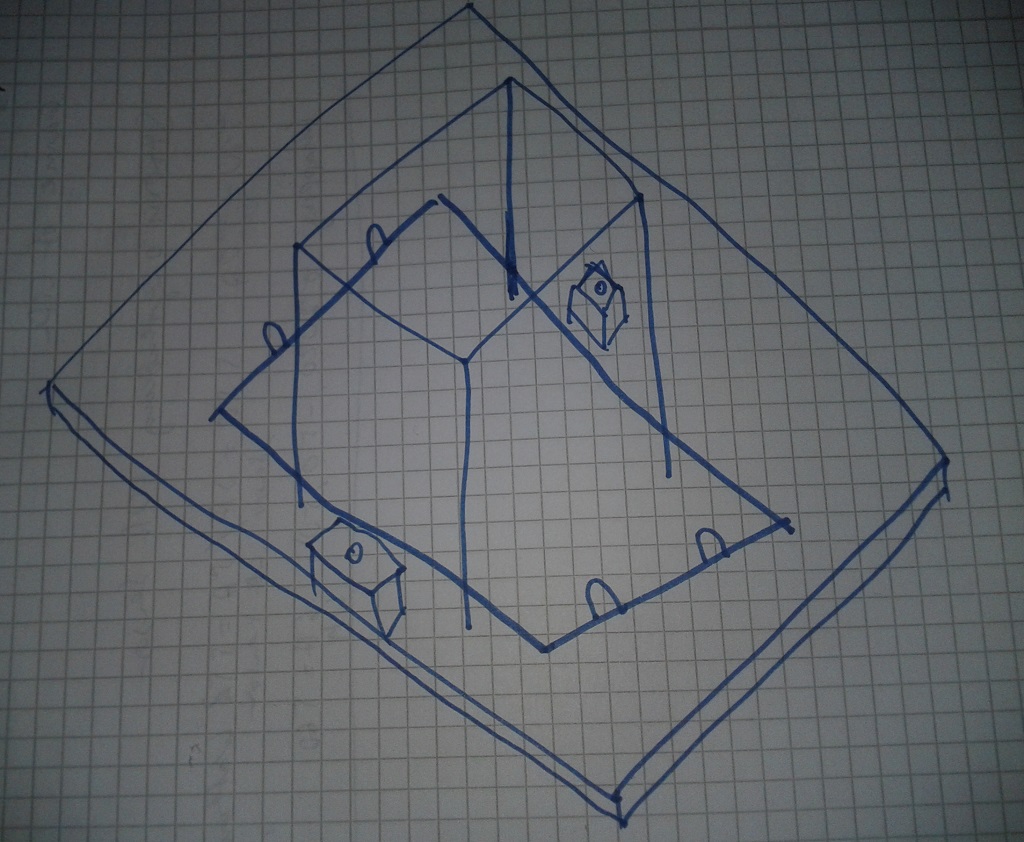
Sorry, you misunderstood my suggestion.
I made a sketch of it, but my drawings skills are even worse than my english
My idea is to fit the widened y-frame between the verticals. Then you have to move the z-steppers too, but it's all mounted on a stiff plate.
I made a sketch of it, but my drawings skills are even worse than my english
My idea is to fit the widened y-frame between the verticals. Then you have to move the z-steppers too, but it's all mounted on a stiff plate.
|
Re: New Reprap Printer, Calling it, the KittyCat! December 29, 2016 03:38AM |
Registered: 8 years ago Posts: 1,671 |
|
Re: New Reprap Printer, Calling it, the KittyCat! December 29, 2016 07:18AM |
Registered: 9 years ago Posts: 1,873 |
Quote
MechaBits
Maybe use one dual shaft motor, for the Z and run a belt underneath(right through the cat litter) to other side.
That's an excellent idea for this sort of layout.
I also agree with o_lampe, there is some redundancy in the frame that I don't think is bringing much structural advantage. You could extend the lower Y extrusion of the middle/vertical part of the frame and then complete the square for the base with very few changes other than possibly having to add a spacer on the mounts for the Y axis rods. Just checked o_lampe's drawing, and yes, that's the way I would do it.
You'd reduce the amount of extrusion required without significantly reducing the rigidity of the printer. Functionally, you'd end up with a cleaner, better designed and stronger version of my first printer
I see this sort of layout as a well evolved version of the Prusa i3, especially if you go with a single motor Z and the thicker smooth rods. The next step up would be to expand the frame to a full cube so that it can be easily enclosed and go with either supported smooth rods or linear guides. That moves it far enough away from the original low cost motivation of the i3 design that it would be worth calling it something different (do we have anything like that as a documented open design?).
|
Re: New Reprap Printer, Calling it, the KittyCat! December 29, 2016 08:15AM |
Registered: 8 years ago Posts: 3,525 |
Smartrapcore is probably the closest to that, okay its a corexy but it's an open source cuboid 2020 frame printer.
Simon Khoury
Co-founder of [www.precisionpiezo.co.uk] Accurate, repeatable, versatile Z-Probes
Published:Inventions
Simon Khoury
Co-founder of [www.precisionpiezo.co.uk] Accurate, repeatable, versatile Z-Probes
Published:Inventions
|
Re: New Reprap Printer, Calling it, the KittyCat! December 29, 2016 08:35AM |
Registered: 9 years ago Posts: 1,873 |
Quote
DjDemonD
Smartrapcore is probably the closest to that, okay its a corexy but it's an open source cuboid 2020 frame printer.
True, but I think there is still value in the moving Y axis bed design for first time builders - the simplicity of the motion system makes is it very easy to debug and setup. DigitalDentist has won me over on the argument about trying to scrape the bottom of the barrel for cost savings though, so I'd like to see a good quality Prusa i3 like design on the wiki as an option that we could suggest to first-time builders. Perhaps this could be it
|
Re: New Reprap Printer, Calling it, the KittyCat! December 29, 2016 09:15AM |
Registered: 8 years ago Posts: 3,525 |
Totally agree, this design might be a good step up from an i3. But it's hard not to look at it and conclude it's just 4 slightly longer extrusions in y dimension from being a cube frame and being a much better printer for it.
Maybe this is the answer - start with this frame, then upgrade it to a cube frame, putting the replaced extrusions to one side to later make a z axis with, but with sliding y axis still and then upgrade it in a modular fashion to a corexy.
Simon Khoury
Co-founder of [www.precisionpiezo.co.uk] Accurate, repeatable, versatile Z-Probes
Published:Inventions
|
Re: New Reprap Printer, Calling it, the KittyCat! December 29, 2016 09:19AM |
Registered: 9 years ago Posts: 25 |
|
Re: New Reprap Printer, Calling it, the KittyCat! December 29, 2016 02:46PM |
Registered: 8 years ago Posts: 601 |
Quote
DjDemonD
Totally agree, this design might be a good step up from an i3. But it's hard not to look at it and conclude it's just 4 slightly longer extrusions in y dimension from being a cube frame and being a much better printer for it.
Maybe this is the answer - start with this frame, then upgrade it to a cube frame, putting the replaced extrusions to one side to later make a z axis with, but with sliding y axis still and then upgrade it in a modular fashion to a corexy.
So why not just make a 2nd printer? After you've bought all the extrusions to do it bit by bit, you could just make a new printer with corexy... I don't see why a cube would be so much better than this frame. Assuming the extrusion is bolted together properly (tapped ends) it will be more than strong enough for printing with.
I think the moving Y axis is fine, but you need to be realistic about it. 200*200mm is really the max, and you need to design the bed to be as lightweight as possible. Otherwise you never get decent print speeds. Alot of people will start with an underpowered mk2 and thick glass, then chuck on a heat spreader + insulation later and whatever mods they need and before you know it, your bed weighs 1kg and creates ringing and printing problems.
Also, shout out to designing for the electronics now. Your printer looks good on the renders, but chuck in some crazy wiring and it will look like the spaghetti monster
|
Re: New Reprap Printer, Calling it, the KittyCat! December 29, 2016 07:21PM |
Registered: 9 years ago Posts: 42 |
The bed I'm planning on using is my old 200x200MM prusa i3 aluminum laser cut plate. I am thinking that a silicon heated bed would be lighter and better for a heatbed. Or I could skip the heated altogether and use something extremely light like laser cut melamine.
I also looked at the belt driven z axis posted by MechaBits. Besides needing one less motor. What are the advantages of this? If the leadscrews are straight than there should not be any difference. I also thought of another belt driven z axis design. What if I mounted a stepper motor in the center of the frame, and used a dual GT2 pulley to drive 2 more pulleys installed near the bottom of the leadscrews. The z axis is not directly controlled by belts but you would only need 1 motor.
I will start working on Electronics mounting now.
Edited 1 time(s). Last edit at 12/29/2016 07:25PM by zastin17.
|
Re: New Reprap Printer, Calling it, the KittyCat! December 29, 2016 07:47PM |
Registered: 8 years ago Posts: 3,525 |
Don't discount a belt driven z axis, I have one and it performs very well for much lower cost and complexity than multiple leadscrew systems. The resolution is plenty with a 0.9 deg motor and 16t pulley. I much prefer it to a leadscrew coupled to a nema 17 motor with a flexible coupler.
The only real drawback is the bed free falls when powered off, so fit some springs or a counterweight.
Simon Khoury
Co-founder of [www.precisionpiezo.co.uk] Accurate, repeatable, versatile Z-Probes
Published:Inventions
The only real drawback is the bed free falls when powered off, so fit some springs or a counterweight.
Simon Khoury
Co-founder of [www.precisionpiezo.co.uk] Accurate, repeatable, versatile Z-Probes
Published:Inventions
|
Re: New Reprap Printer, Calling it, the KittyCat! December 29, 2016 10:10PM |
Registered: 9 years ago Posts: 199 |
Hi Zastin17,
I am in the progress of making a custom mendelmax 1.5, i remodeld pretty much all printed parts , maybe i can give you some advice.
A good thing you changed the z axis design to 2 leadscrews on each side.
I think your y axis extrusions would be better of if they touched the ground , even if it doesn't really shake, the other extrusions will have to take all the vibrations from the op ones, like said above, you may want to consider a cube shape.
It would save you 4 extrusions, and it would only take 4 extrusions to be longer then they are now ( increased rigidity and you gain z height).
I like how you want the put your x axis belt, i just don't really see how you will combine this with the hotend etc.
I can also advice you to go bowden to print much smoother and faster , it is definitely worth it !
Below pictures of my setup, also check this printer :[www.thingiverse.com]
Keep up the good work, and good luck.
Edited 4 time(s). Last edit at 12/30/2016 11:06AM by Govahnator.
I am in the progress of making a custom mendelmax 1.5, i remodeld pretty much all printed parts , maybe i can give you some advice.
A good thing you changed the z axis design to 2 leadscrews on each side.
I think your y axis extrusions would be better of if they touched the ground , even if it doesn't really shake, the other extrusions will have to take all the vibrations from the op ones, like said above, you may want to consider a cube shape.
It would save you 4 extrusions, and it would only take 4 extrusions to be longer then they are now ( increased rigidity and you gain z height).
I like how you want the put your x axis belt, i just don't really see how you will combine this with the hotend etc.
I can also advice you to go bowden to print much smoother and faster , it is definitely worth it !
Below pictures of my setup, also check this printer :[www.thingiverse.com]
Keep up the good work, and good luck.


Edited 4 time(s). Last edit at 12/30/2016 11:06AM by Govahnator.
|
Re: New Reprap Printer, Calling it, the KittyCat! January 03, 2017 08:02AM |
Registered: 8 years ago Posts: 413 |
Here is a few considerations.
Have you considered making the frame wider in Y? It will be more stable, big enough to make into an enclosure?.
Your current design looks like the centre of the bed will be over the lower frame in max and min Y position. If its any further you could lose stability. Triangulation gives the greatest rigidity so strong beams may not be as useful as triangulated corners
You will also need some stops to prevent the Y rails sliding out the brackets so you could design blind holes into the existing brackets. I would also suggest you make one of these adjustable in Z so you can ensure the shafts are parallel. Obviously you can adjust the current brackets in X but your Z height is currently reliant on all the brackets being identical.
Its to hard to explain the complexities of tolerances but I would not use 4 Z guides. Ideally 2 is the max and one of those should really be in a slot in X. this means that one shaft controls the X/Y position at one end and the other simply stops the other end rotating.
You also need to ensure the X axis length is fixed. It looks like you have blind holes in the motor end. Not sure how you are fixing the other end but don't let the shafts slide in the far end or the tension in the belt will pull the two ends towards each other. I have through holes on my P3 but I have added an adjustable end stop so the shafts can't move.
You might want to consider allowing more space around the motors. Some people have issues with motor temperature. You are severely limiting the airflow with your current brackets so they may be difficult to keep cool - or vise versa you can heat up the brackets causing expansion that gives some issues later.
Sorry, only registered users may post in this forum.