Stepper motor wiring...
Posted by saintofinternet
|
Stepper motor wiring... January 03, 2017 10:46PM |
Registered: 7 years ago Posts: 34 |
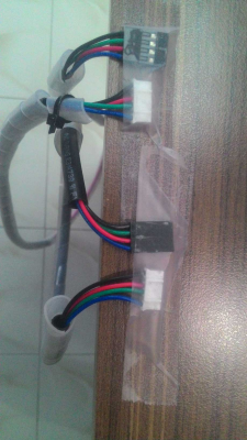
please check the attached image...
it is about the wiring which was sent to me by the supplier of an prusa i3 replica for the stepper motor to controller board.
i am confused because the wiring to my knowledge needs to be straight... but here the middle 2 wires are crossed...
help appreciated....
it is about the wiring which was sent to me by the supplier of an prusa i3 replica for the stepper motor to controller board.
i am confused because the wiring to my knowledge needs to be straight... but here the middle 2 wires are crossed...
help appreciated....
|
Re: Stepper motor wiring... January 04, 2017 03:00AM |
Admin Registered: 13 years ago Posts: 7,001 |
There is no standard for the stepper end. It is entirely dependant on your stepper motors. there is nothing that says it "needs to be straight"
Basically plug the cable into the stepper, from the black plug end check with a multimeter that there is continuity from pins 1 and 2 and continuity from pins 3 and 4. this is the nornal for ramps and all other reprap controllers (that I know of)
There should be nothing from any other combinations.
Edited 1 time(s). Last edit at 01/04/2017 03:02AM by Dust.
|
Re: Stepper motor wiring... January 04, 2017 09:13AM |
Registered: 12 years ago Posts: 2,470 |
Usually the connectors feature one pair of wires for coil A on one side and the other pair on the other side for coil B.
By switching the pairs or by switching the wires within any pair you can reverse the direction. If however you mix up wires from coil A and B things stop working.
If the motors are all of the same type the colorcoding of the wires should be identical. However, i can see two different kinds of connectors, so propably you are using two different types of motors. It seems the motors have just differently color coded wires.
[www.bonkers.de]
[merlin-hotend.de]
[www.hackerspace-ffm.de]
|
Re: Stepper motor wiring... January 04, 2017 10:32AM |
Registered: 7 years ago Posts: 759 |
|
Re: Stepper motor wiring... January 04, 2017 09:59PM |
Registered: 7 years ago Posts: 34 |
|
Re: Stepper motor wiring... January 04, 2017 10:03PM |
Registered: 7 years ago Posts: 34 |
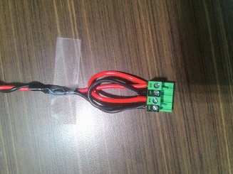
i have put the power cables in loop for the positive and negative... helping me keep one set of +Ve/-Ve terminals free on PSU.
i wanted to know if this is ok to keep them in the loop? as the output voltage is 12V and the Amp is also same from the PSU....
suggestions please...
|
Re: Stepper motor wiring... January 05, 2017 03:11AM |
Registered: 12 years ago Posts: 2,470 |
A bit more information on what you are actually doing and using would go a long way to help you.
Are you using a heated bed that is directly connected to the electronics? Is that connector used for both the motor power and the heatbed power? If yes your wiring is woefully inadequate. Read up on the power requirements and double check what wire size you need, otherwise you might end up with molten insulation and glowing wires, if not a fire.
[www.bonkers.de]
[merlin-hotend.de]
[www.hackerspace-ffm.de]
|
Re: Stepper motor wiring... January 05, 2017 05:47AM |
Registered: 7 years ago Posts: 34 |
Yes it is powering both the motors and the bed....
Each wire is 1.50sqmm ( between 15-16 AWG ) which I think is enough for the required current to pass through.
Now what puzzels me is if the loop that is on the connector not the right way why aste people supplying prusa i3 clone sending such wires which happen to work....
Ofcourse i am ready to make changes if suggested
|
Re: Stepper motor wiring... January 05, 2017 07:54AM |
Registered: 7 years ago Posts: 759 |
|
Re: Stepper motor wiring... January 05, 2017 10:35PM |
Registered: 7 years ago Posts: 34 |
Sorry, only registered users may post in this forum.

