External Mosfet boards actually quite good!
Posted by DjDemonD
|
External Mosfet boards actually quite good! April 22, 2017 07:26AM |
Registered: 8 years ago Posts: 3,525 |
So I was using a mechanical relay for my 24v heated bed on my corexy which has a second power supply.
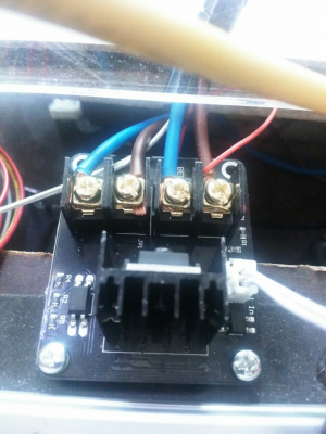
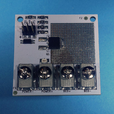
So I bought one of these external mosfet boards and wired it up.
My second psu is 250w so it handles around 12amps without even getting warm. And I'm back to using pwm for the bed rather than bang bang.
So much more pleased with it for £4.25 than I thought I was going to be.
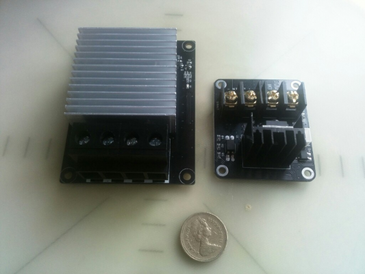
I also bought another one
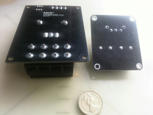
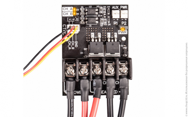
Which is absolutely massive it's probably as large as the ramps/rearm boards running the printer, has connectors which look like they could probably handle 50amps and seems totally over the top but only cost me £9 delivered. Quite nicely made though all machine soldered etc...
Compared to DC-DC ssr these seem much more useful especially for really large beds if AC mains is not going to be used.
Edited 2 time(s). Last edit at 04/22/2017 07:46AM by DjDemonD.
Simon Khoury
Co-founder of [www.precisionpiezo.co.uk] Accurate, repeatable, versatile Z-Probes
Published:Inventions
|
Re: External Mosfet boards actually quite good! April 22, 2017 11:25AM |
Registered: 7 years ago Posts: 41 |
|
Re: External Mosfet boards actually quite good! April 22, 2017 11:41AM |
Registered: 8 years ago Posts: 3,525 |
Both of these are quite well made the larger one very well made (makerbase), although I haven't actually powered it up yet. The smaller (unknown brand) one the high current connectors twist a bit when you do the screws up but hold them whilst doing it and you're golden.
Simon Khoury
Co-founder of [www.precisionpiezo.co.uk] Accurate, repeatable, versatile Z-Probes
Published:Inventions
Simon Khoury
Co-founder of [www.precisionpiezo.co.uk] Accurate, repeatable, versatile Z-Probes
Published:Inventions
|
Re: External Mosfet boards actually quite good! April 22, 2017 12:32PM |
Registered: 8 years ago Posts: 1,671 |
I was tempted with this one as its big black n red...looks good
[www.ebay.co.uk]
though this looks similar but bigger
[www.ebay.co.uk]
Edited 1 time(s). Last edit at 04/22/2017 12:34PM by MechaBits.
[www.ebay.co.uk]
though this looks similar but bigger
[www.ebay.co.uk]
Edited 1 time(s). Last edit at 04/22/2017 12:34PM by MechaBits.
|
Re: External Mosfet boards actually quite good! April 22, 2017 12:39PM |
Registered: 8 years ago Posts: 3,525 |
Yeah those are the same as the big one I have but haven't used yet. It has 4 low side inputs one pair are marked d8 which makes sense the other are marked bed + and - so not sure what the difference is?
Simon Khoury
Co-founder of [www.precisionpiezo.co.uk] Accurate, repeatable, versatile Z-Probes
Published:Inventions
Simon Khoury
Co-founder of [www.precisionpiezo.co.uk] Accurate, repeatable, versatile Z-Probes
Published:Inventions
|
Re: External Mosfet boards actually quite good! April 22, 2017 02:36PM |
Registered: 7 years ago Posts: 45 |
|
Re: External Mosfet boards actually quite good! April 23, 2017 02:16AM |
Registered: 10 years ago Posts: 14,672 |
Those boards are in effect un-encapsulated 5-terminal SSRs. Unlike normal 4-terminal SSRs, the gate voltage seen by the mosfet may be the full supply voltage if the board doesn't include components to limit it, and since many power MOSFETs have a gate voltage rating of 20V this could make operation on 24V inadvisable. The turn-off time may be quite slow, in which case they are likely to get hot if you use them with fast PWM.
Large delta printer [miscsolutions.wordpress.com], E3D tool changer, Robotdigg SCARA printer, Crane Quad and Ormerod
Disclosure: I design Duet electronics and work on RepRapFirmware, [duet3d.com].
Large delta printer [miscsolutions.wordpress.com], E3D tool changer, Robotdigg SCARA printer, Crane Quad and Ormerod
Disclosure: I design Duet electronics and work on RepRapFirmware, [duet3d.com].
|
Re: External Mosfet boards actually quite good! April 23, 2017 05:37AM |
Registered: 9 years ago Posts: 25 |
I Like to use these things: (German) Fredee RMCS
couldn't find an english Version so here's the Google translated one:
(Translated) Fredee RMCS
I don't know much about electronics, but they seem to work really well. I use them to run 12v PCB heaters on 24v.
couldn't find an english Version so here's the Google translated one:
(Translated) Fredee RMCS
I don't know much about electronics, but they seem to work really well. I use them to run 12v PCB heaters on 24v.
|
Re: External Mosfet boards actually quite good! April 23, 2017 06:31AM |
Registered: 8 years ago Posts: 3,525 |
Quote
dc42
Those boards are in effect un-encapsulated 5-terminal SSRs. Unlike normal 4-terminal SSRs, the gate voltage seen by the mosfet may be the full supply voltage if the board doesn't include components to limit it, and since many power MOSFETs have a gate voltage rating of 20V this could make operation on 24V inadvisable. The turn-off time may be quite slow, in which case they are likely to get hot if you use them with fast PWM.
Okay so you're saying switching it with 24v might be a problem, but switching it with 12v is okay right? There are other components on these boards I suspect one is a regulator to feed the mosfet whatever its ideal gate voltage is.
Simon Khoury
Co-founder of [www.precisionpiezo.co.uk] Accurate, repeatable, versatile Z-Probes
Published:Inventions
|
Re: External Mosfet boards actually quite good! April 23, 2017 07:16AM |
Registered: 8 years ago Posts: 5,232 |
|
Re: External Mosfet boards actually quite good! April 23, 2017 08:37AM |
Registered: 10 years ago Posts: 14,672 |
The 4-legged component on these boards is normally an opto coupler. There will also be at least 2 resistors, one on the input side of the opto coupler and one on the output side. If there are no other components apart from these, the mosfet and the connectors, then you should assume that the mosfet gets the full supply voltage applied to its gate. If you can read the part number on the mosfet, you can look up the maximum gate voltage on its datasheet. It's often 20V, but may be higher for some types, and lower for logic-level mosfets.
Large delta printer [miscsolutions.wordpress.com], E3D tool changer, Robotdigg SCARA printer, Crane Quad and Ormerod
Disclosure: I design Duet electronics and work on RepRapFirmware, [duet3d.com].
Large delta printer [miscsolutions.wordpress.com], E3D tool changer, Robotdigg SCARA printer, Crane Quad and Ormerod
Disclosure: I design Duet electronics and work on RepRapFirmware, [duet3d.com].
|
Re: External Mosfet boards actually quite good! April 23, 2017 09:22AM |
Registered: 8 years ago Posts: 3,525 |
I'll have a much closer look at the components when I get home.
Simon Khoury
Co-founder of [www.precisionpiezo.co.uk] Accurate, repeatable, versatile Z-Probes
Published:Inventions
Simon Khoury
Co-founder of [www.precisionpiezo.co.uk] Accurate, repeatable, versatile Z-Probes
Published:Inventions
|
Re: External Mosfet boards actually quite good! April 23, 2017 01:40PM |
Registered: 8 years ago Posts: 3,525 |
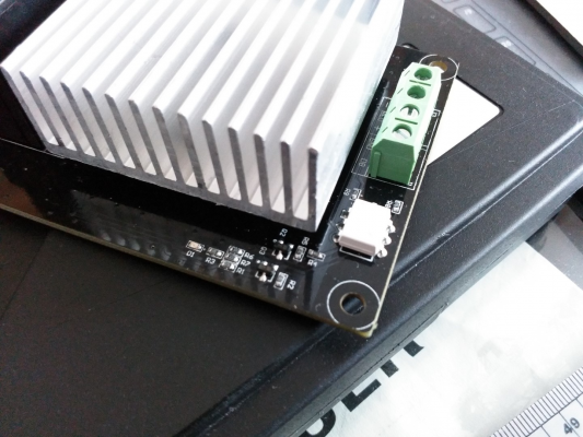
Here's an image of the components on the larger one, theres nothing else except the mosfet (which is under the heatsink so not really accessible without taking it apart) and connectors.
Heres the full res image if it helps.
[1drv.ms]
As for the smaller one the mosfet on it has
HL
EBO P35
HA210N06
on it.
Edited 2 time(s). Last edit at 04/23/2017 02:20PM by DjDemonD.
Simon Khoury
Co-founder of [www.precisionpiezo.co.uk] Accurate, repeatable, versatile Z-Probes
Published:Inventions
Heres the full res image if it helps.
[1drv.ms]
As for the smaller one the mosfet on it has
HL
EBO P35
HA210N06
on it.
Edited 2 time(s). Last edit at 04/23/2017 02:20PM by DjDemonD.
Simon Khoury
Co-founder of [www.precisionpiezo.co.uk] Accurate, repeatable, versatile Z-Probes
Published:Inventions
|
Re: External Mosfet boards actually quite good! April 23, 2017 03:23PM |
Registered: 10 years ago Posts: 14,672 |
The big one has two transistors on it as well as the opto coupler and mosfet, so someone may have thought about the design a bit. My guess is that the two small transistor are for providing higher gate drive so that it switches faster.
The datasheet for the HA210N06 mosfet here [www.cecb2b.com] specifies the maximum gate-source voltage as 25V. The smaller board has a few extra components too, so it may be designed to handle more than 25V input.
Large delta printer [miscsolutions.wordpress.com], E3D tool changer, Robotdigg SCARA printer, Crane Quad and Ormerod
Disclosure: I design Duet electronics and work on RepRapFirmware, [duet3d.com].
|
Re: External Mosfet boards actually quite good! April 24, 2017 06:43AM |
Registered: 8 years ago Posts: 126 |
Please advise me :
if using the smaller of the 2 Mosfet modules ( as in the OP ) what is the best way to connect Ramps to the Gate ? Do you ....
1. remove the Ramps on-board Mosfet and bridge the trace for the ( removed ) on-board Mosfet Gate to the Input / Gate of the Mosfet Module
or
2. leave the on-board Mosfet on the board and use the signal coming from the on-board Mosfet ( via teminals D8 ) to control the input of the Mosfet module ?
Regards
|
Re: External Mosfet boards actually quite good! April 24, 2017 06:54AM |
Registered: 8 years ago Posts: 3,525 |
No. 2. There is no reason not to, the output from the ramps D8 Mosfet will only draw the current of the load attached to it, if this is a bed heater then 10A+ if its the external mosfet board (I will measure the current later if you like) I suspect a few milli-amps.
You could remove your ramps D8 mosfet but you stand to gain nothing by doing so, or better still change your pins file to use a spare PWM output pin as the Bed heater pin, thereby freeing up the D8 ramps mosfet to control a second fan or chamber heater or whatever you wanted. I haven't tried this but there is no reason why it wouldn't work. Easy enough to test. Select an unused pin from schematic of the ramps/mega combo, change the pins.h file in the marlin folder to this new pin (pins are described by their number on the arduino, rather than the ramps), and connect this to the + of the input on the external mosfet board, the negative can be connected to any ground pin/PSU etc...
The only potential issue and it might be nice to know if this works is that the output pin will output 5v PWM rather than 12v PWM. I am curious to know if these additional components on the external mosfet board can accommodate a wide range of signal voltages.
I'll try it later on, I'd quite like to free up a PWM output for something else.
Edited 1 time(s). Last edit at 04/24/2017 07:22AM by DjDemonD.
Simon Khoury
Co-founder of [www.precisionpiezo.co.uk] Accurate, repeatable, versatile Z-Probes
Published:Inventions
|
Re: External Mosfet boards actually quite good! April 24, 2017 07:27AM |
Registered: 8 years ago Posts: 126 |
Thank You DjDemonD
Only just ordered the module so will take a while to arrive.
Thanks for the guidance and the ideas.
I suppose if the module does not work with a 5V signal, we could always beef up the signal with a transistor, or something like a 4N25 opto, controlled by 5V from the output pin, and connect the 12V PSU to the Mosfet Module Input.
|
Re: External Mosfet boards actually quite good! April 24, 2017 07:43AM |
Registered: 8 years ago Posts: 3,525 |
Or, and I am being a little sarcastic here, just beef it up using the D8 Mosfet!
Simon Khoury
Co-founder of [www.precisionpiezo.co.uk] Accurate, repeatable, versatile Z-Probes
Published:Inventions
Simon Khoury
Co-founder of [www.precisionpiezo.co.uk] Accurate, repeatable, versatile Z-Probes
Published:Inventions
|
Re: External Mosfet boards actually quite good! April 24, 2017 08:41AM |
Registered: 7 years ago Posts: 12 |
|
Re: External Mosfet boards actually quite good! April 24, 2017 09:25AM |
Registered: 8 years ago Posts: 126 |
|
Re: External Mosfet boards actually quite good! April 24, 2017 10:44PM |
Registered: 7 years ago Posts: 41 |
Quote
dc42
Those boards are in effect un-encapsulated 5-terminal SSRs. Unlike normal 4-terminal SSRs, the gate voltage seen by the mosfet may be the full supply voltage if the board doesn't include components to limit it, and since many power MOSFETs have a gate voltage rating of 20V this could make operation on 24V inadvisable. The turn-off time may be quite slow, in which case they are likely to get hot if you use them with fast PWM.
For the smaller one, the two outside solder terminals in the group of 5 are actually just posts securing the heat sink to the pcb. The mosfet only has 3 terminals connecting to the pcb. The number on the mosfet is HA210N06
|
Re: External Mosfet boards actually quite good! April 25, 2017 02:38AM |
Registered: 10 years ago Posts: 14,672 |
Quote
Pheneeny
Quote
dc42
Those boards are in effect un-encapsulated 5-terminal SSRs. Unlike normal 4-terminal SSRs, the gate voltage seen by the mosfet may be the full supply voltage if the board doesn't include components to limit it, and since many power MOSFETs have a gate voltage rating of 20V this could make operation on 24V inadvisable. The turn-off time may be quite slow, in which case they are likely to get hot if you use them with fast PWM.
For the smaller one, the two outside solder terminals in the group of 5 are actually just posts securing the heat sink to the pcb. The mosfet only has 3 terminals connecting to the pcb. The number on the mosfet is HA210N06
That board actually has 6 terminals: two power in, two power out, and two control (the white plastic connector). But one of the power in terminals is commoned with one of the power out terminals, which is why I called it a 5-terminal SSR.
Large delta printer [miscsolutions.wordpress.com], E3D tool changer, Robotdigg SCARA printer, Crane Quad and Ormerod
Disclosure: I design Duet electronics and work on RepRapFirmware, [duet3d.com].
|
Re: External Mosfet boards actually quite good! May 01, 2017 01:34PM |
Registered: 8 years ago Posts: 9 |
For this one, we developed this board about half a year ago ($25 shipped worldwide), so feel free to ask any questions.
Full English complete datasheet: http://www.cheap3d.ru/shop/cheap3d_mosfet_switch_board_datasheet_en.pdf
|
Re: External Mosfet boards actually quite good! May 01, 2017 03:27PM |
Registered: 7 years ago Posts: 270 |
|
Re: External Mosfet boards actually quite good! May 01, 2017 04:06PM |
Registered: 8 years ago Posts: 126 |
Quote
newbob
I read that failed MOSFETs often short-circuit therefore two modules in series are needed to protect from runaway heater. I'm not sure however how well two in series would work in PWM mode.
This is a very interesting point, and I imagine this could be as much as problem for the Ramps on-board Mosfet, just as much as an external Mosfet.
So the simplest solution that I see is to have a basic relay in series before the Mosfet module, connected to a digital pin on Ramps.
In the starting gCode, set the digital pin High to enable power to the Mosfet.
At the end of the gCode, set the digital pin Low to disable power to the Mosfet.
Lastly, modify Marlin, so that in the event of an Max Bed Temperature condition, set the digital pin LOW, which removes any power going to the Mosfet.
|
Re: External Mosfet boards actually quite good! May 01, 2017 04:11PM |
Registered: 8 years ago Posts: 9 |
It's not a good engineering practice to put two MOSFETs in series. Nobody does this even in Space/Military applications.Quote
newbob
I read that failed MOSFETs often short-circuit therefore two modules in series are needed to protect from runaway heater. I'm not sure however how well two in series would work in PWM mode.
MOSFETs do not fail just by surprise. There is a closed (and pretty short) list of possible reasons leading to MOSFET fail. Like: series resistor on gate, some measures to protect overvoltage, freewheeling diode to protect from inductive spikes.
Good engineering practice is to implement all these types of protections for a single MOSFETs rather than making two unprotected MOSFETs. The first would work, the second would ruin both MOSFETs.
BTW, RAMPS/RUMBA/RAMBO/MKS/etc (in fact, all the boards that I tested) lack those protections. So it's a good idea to install a better engineered external switching board instead of using the regular outputs.
|
Re: External Mosfet boards actually quite good! May 01, 2017 05:23PM |
Registered: 7 years ago Posts: 270 |
Quote
DaveOB
Quote
newbob
I read that failed MOSFETs often short-circuit therefore two modules in series are needed to protect from runaway heater. I'm not sure however how well two in series would work in PWM mode.
This is a very interesting point, and I imagine this could be as much as problem for the Ramps on-board Mosfet, just as much as an external Mosfet.
So the simplest solution that I see is to have a basic relay in series before the Mosfet module, connected to a digital pin on Ramps.
In the starting gCode, set the digital pin High to enable power to the Mosfet.
At the end of the gCode, set the digital pin Low to disable power to the Mosfet.
Lastly, modify Marlin, so that in the event of an Max Bed Temperature condition, set the digital pin LOW, which removes any power going to the Mosfet.
Good idea. Maybe, instead of two mosfets in series use NO relay (controlled by marlin as you described) and MOSFETs for individual heaters. Some relays have more than two NO leads, one set could be connected to hotbed MOSFET the other to hotend MOSFET board.
Edited 1 time(s). Last edit at 05/01/2017 05:26PM by newbob.
|
Re: External Mosfet boards actually quite good! May 01, 2017 05:46PM |
Registered: 8 years ago Posts: 126 |
Quote
newbob
Some relays have more than two NO leads, one set could be connected to hotbed MOSFET the other to hotend MOSFET board.
If we use an external Mosfet Module for the bed and another Module for the hotend, then we can add a NO relay between the PSU and the 2 modules ( split the output from the relay to the 2 modules ). In this setup, any MaxTemp fault would terminate power to both the bed and the hotend at the same time.
As far as I understand on Ramps, the power for the hotend heaters is taken from the 5A input, and the 11A input is used only for the bed heater.
So without modifying the ramps board there would be no way to add the NO relay to the power going to the Mosfet for the on-board hotend, as that feed also powers everything on Ramps and the Mega.
My preference would be to have 2 external Mosfet modules that remove all high current from Ramps. Managing a MaxTemp error becomes a much easier process.
|
Re: External Mosfet boards actually quite good! May 01, 2017 07:12PM |
Registered: 8 years ago Posts: 3,525 |
There are a couple of other ideas you might want to consider. PS-on signal from ramps, provided 5v is supplied (by usb from pc/Octoprint or a 5v USB adaptor) gcodes m80/m81 can be used to switch the psu on/off thereby killing power to hotend and heatbed (provided you're using one rather than 2 power supplies) designed to work with original x box psu which supplies an always on 5v rail and a switchable 12v rail, but you could substitute one of the larger mosfet boards (provided they switch on 5v, I assume the alternative digital connectors on the trigorilla type do this). You would still use a smaller one for the bed, if it failed-open then you could maybe expect the firmware to send m81 and kill power on the large mosfet unit and therefore all heaters or configure it to do so.
Also use of a thermal fuse under the bed in series with the bed power is a very useful safety feature costing just £1 and which works especially well in the event of a mosfet failed-open.
Also if you're going to use these things then don't use mechanical relays, surely the idea is to replace clunky mechanical relays with something better otherwise use a mechanical relay for the bed heater, they fail safe mostly, and use a 5v relay for ps-on if you want that extra layer of safety also.
Edited 3 time(s). Last edit at 05/01/2017 08:01PM by DjDemonD.
Simon Khoury
Co-founder of [www.precisionpiezo.co.uk] Accurate, repeatable, versatile Z-Probes
Published:Inventions
|
Re: External Mosfet boards actually quite good! June 06, 2020 12:15PM |
Registered: 4 years ago Posts: 1 |
Sorry to necro this thread, but I have an answer! At least, about the question about the external MOSFET and the output pins.
TL;DR: 3.3V will NOT turn on the clone MOSFET boards
How I determined this:
I have an BIGTREETECH SKR PRO V1.0
My bed MOSFET blew out on it; been printing > $7k worth of masks and PPE for COVID-19.I forgot to check the max wattage - board says its' 180W. I had external MOSFET's but was busy printing PPE and didn't print the new enclosure. Sigh.
So, I tried taking a line from one of the expansion output pins, PF10 in this case, and wired over to the MOSFET. I have a BTTMOS V2.0 (BigTreeTech/BIQU).
I checked with a multimeter- was producing 3.3V between ground and the output pin. Ran that into the external MOSFET. It did not turn on.
So, I unwired my electronics fan, which I'd connected to HEATER_2_PIN as I am only using 2 extruders, and wired that to the external MOSFET.
The BTTMOS bed output measured 12v, when it's on as I'd expect (Bed PS is 12V), and sure enough, a second blue LED lit up on the external MOSFET and my bed started heating once I connected it.
So, not sure if the MOSFET turns on via 5V, but it defintely doesn't with 3.3V and will at 12V.
== John ==
TL;DR: 3.3V will NOT turn on the clone MOSFET boards

How I determined this:
I have an BIGTREETECH SKR PRO V1.0
My bed MOSFET blew out on it; been printing > $7k worth of masks and PPE for COVID-19.I forgot to check the max wattage - board says its' 180W. I had external MOSFET's but was busy printing PPE and didn't print the new enclosure. Sigh.
So, I tried taking a line from one of the expansion output pins, PF10 in this case, and wired over to the MOSFET. I have a BTTMOS V2.0 (BigTreeTech/BIQU).
I checked with a multimeter- was producing 3.3V between ground and the output pin. Ran that into the external MOSFET. It did not turn on.
So, I unwired my electronics fan, which I'd connected to HEATER_2_PIN as I am only using 2 extruders, and wired that to the external MOSFET.
The BTTMOS bed output measured 12v, when it's on as I'd expect (Bed PS is 12V), and sure enough, a second blue LED lit up on the external MOSFET and my bed started heating once I connected it.
So, not sure if the MOSFET turns on via 5V, but it defintely doesn't with 3.3V
 and will at 12V.
 == John ==
Sorry, only registered users may post in this forum.
