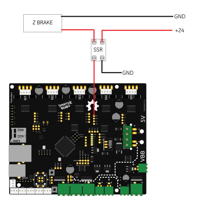
How to wire a z axis brake on my build ?
Posted by paboman
|
How to wire a z axis brake on my build ? April 25, 2017 10:42AM |
Registered: 8 years ago Posts: 29 |
Hi, I'm building a cartesian 3d printer, as per customer request and for security reason the machine will be equipped with a magnetic brake on the Z axis.
I want to be able to wire it so when the motors are energized and holding position the brake will be energized also.
Can i use the Enable pin of the stepper driver to drive a DC solid state relay ?
any help is appreciated
Edited 1 time(s). Last edit at 04/25/2017 10:43AM by paboman.
I want to be able to wire it so when the motors are energized and holding position the brake will be energized also.
Can i use the Enable pin of the stepper driver to drive a DC solid state relay ?
any help is appreciated
Edited 1 time(s). Last edit at 04/25/2017 10:43AM by paboman.
|
Re: How to wire a z axis brake on my build ? April 25, 2017 11:26AM |
Registered: 10 years ago Posts: 14,672 |
The enable pin is active low for most internal stepper drivers, so if you want the brake to be energised when the motor is enabled then you must connect the SSR between the Enable pin and either +3.3V or +5V depending on whether the Enable signal is a 3.3V or a 5V output on your electronics.
If the brake is basically a solenoid then you should connect a flyback diode in parallel with it to protect the SSR.
Large delta printer [miscsolutions.wordpress.com], E3D tool changer, Robotdigg SCARA printer, Crane Quad and Ormerod
Disclosure: I design Duet electronics and work on RepRapFirmware, [duet3d.com].
|
Re: How to wire a z axis brake on my build ? April 25, 2017 12:01PM |
Registered: 8 years ago Posts: 29 |
|
Re: How to wire a z axis brake on my build ? April 25, 2017 12:57PM |
Registered: 12 years ago Posts: 2,470 |
A flyback diode protects the electronics from the resurging current when a solenoid is switched off. A 1N4007 will should work.
The diode needs to be connected parallel to the coil so it blocks current that is going the wrong way.
[en.wikipedia.org]
[www.bonkers.de]
[merlin-hotend.de]
[www.hackerspace-ffm.de]
The diode needs to be connected parallel to the coil so it blocks current that is going the wrong way.
[en.wikipedia.org]
[www.bonkers.de]
[merlin-hotend.de]
[www.hackerspace-ffm.de]
Sorry, only registered users may post in this forum.
