Precision Piezo Z-probe Now available.
Posted by DjDemonD
|
Re: Precision Piezo Z-probe Now available. March 07, 2018 03:56AM |
Registered: 9 years ago Posts: 487 |
Sorry for slow replies, it's been a busy week.
Nitram, thanks for that, it's very useful.
Valantin, wiring is explained in the manual but really all you need to do is supply the piezo board with power (3.3v or 5v to V+ and 0v to GND) and connect the SIG pin to your z-probe signal pin (either Zmin or Zmax, I'm not familiar with the controller of the Tornado)
Unfortunately I've not used marlin for about two years, hopefully someone else will be able to chip in and help you with the firmware modifications.
Idris
{Precision Piezo} Accurate, repeatable, versatile z-probe plus piezo discs, endstop cables, pt100, 50w heaters.
|
Re: Precision Piezo Z-probe Now available. March 07, 2018 04:23AM |
Registered: 8 years ago Posts: 3,525 |
Quick summary of Marlin config.
Connect TRG/SIG pin from the piezo board, to the z_min endstop sig pin (on most boards the Z-Min header also has GND and 5v pins to power the piezo board, but please make sure these are connected correctly. We are not responsible for incorrect wiring.
Now in configuration.h go to this area:
uncomment/enable this
So you need to understand whats going on here. Endstop pullups raise the voltage on a pin (using a high value resistor) to 5v until something grounds it. The piezo board is self-powered so it does not need them and they will affect its operation.
So look at how your machine is configured now. If you have coarse endstop pullups enabled (#define ENDSTOPPULLUPS) then comment this out (add //) and then just disable endstop pullup for z_min, but enable it for anything that needed it before (which might be everything else).
Logic should be set to true (but leave everything else as it is) for Z_min.
Next you should enable(uncomment) pause_before_probing
This does what it says it pauses to allow mechanical noise/ringing to stop before probing so the probe doesn't false trigger.
Now test the probe, if you cannot get marlin to register a trigger you might need to change the logic from true to false (I can never get this the right way around from memory).
Edited 2 time(s). Last edit at 03/07/2018 05:08AM by DjDemonD.
Simon Khoury
Co-founder of [www.precisionpiezo.co.uk] Accurate, repeatable, versatile Z-Probes
Published:Inventions
Connect TRG/SIG pin from the piezo board, to the z_min endstop sig pin (on most boards the Z-Min header also has GND and 5v pins to power the piezo board, but please make sure these are connected correctly. We are not responsible for incorrect wiring.
Now in configuration.h go to this area:
#define FIX_MOUNTED_PROBE
uncomment/enable this
// @section homing

// Specify here all the endstop connectors that are connected to any endstop or probe.
// Almost all printers will be using one per axis. Probes will use one or more of the
// extra connectors. Leave undefined any used for non-endstop and non-probe purposes.
#define USE_XMIN_PLUG
#define USE_YMIN_PLUG
#define USE_ZMIN_PLUG
//#define USE_XMAX_PLUG
//#define USE_YMAX_PLUG
//#define USE_ZMAX_PLUG

// coarse Endstop Settings
//#define ENDSTOPPULLUPS // Comment this out (using // at the start of the line) to disable the endstop pullup resistors

#if DISABLED(ENDSTOPPULLUPS)
  // fine endstop settings: Individual pullups. will be ignored if ENDSTOPPULLUPS is defined
  //#define ENDSTOPPULLUP_XMAX
  //#define ENDSTOPPULLUP_YMAX
  //#define ENDSTOPPULLUP_ZMAX
  //#define ENDSTOPPULLUP_XMIN
  //#define ENDSTOPPULLUP_YMIN
  //#define ENDSTOPPULLUP_ZMIN
  //#define ENDSTOPPULLUP_ZMIN_PROBE
#endif

// Mechanical endstop with COM to ground and NC to Signal uses "false" here (most common setup).
#define X_MIN_ENDSTOP_INVERTING false // set to true to invert the logic of the endstop.
#define Y_MIN_ENDSTOP_INVERTING false // set to true to invert the logic of the endstop.
#define Z_MIN_ENDSTOP_INVERTING true // set to true to invert the logic of the endstop.
#define X_MAX_ENDSTOP_INVERTING false // set to true to invert the logic of the endstop.
#define Y_MAX_ENDSTOP_INVERTING false // set to true to invert the logic of the endstop.
#define Z_MAX_ENDSTOP_INVERTING false // set to true to invert the logic of the endstop.
#define Z_MIN_PROBE_ENDSTOP_INVERTING false // set to true to invert the logic of the probe.
So you need to understand whats going on here. Endstop pullups raise the voltage on a pin (using a high value resistor) to 5v until something grounds it. The piezo board is self-powered so it does not need them and they will affect its operation.
So look at how your machine is configured now. If you have coarse endstop pullups enabled (#define ENDSTOPPULLUPS) then comment this out (add //) and then just disable endstop pullup for z_min, but enable it for anything that needed it before (which might be everything else).
Logic should be set to true (but leave everything else as it is) for Z_min.
Next you should enable(uncomment) pause_before_probing
#define DELAY_BEFORE_PROBING 400
This does what it says it pauses to allow mechanical noise/ringing to stop before probing so the probe doesn't false trigger.
Now test the probe, if you cannot get marlin to register a trigger you might need to change the logic from true to false (I can never get this the right way around from memory).
Edited 2 time(s). Last edit at 03/07/2018 05:08AM by DjDemonD.
Simon Khoury
Co-founder of [www.precisionpiezo.co.uk] Accurate, repeatable, versatile Z-Probes
Published:Inventions
|
Re: Precision Piezo Z-probe Now available. March 08, 2018 12:37AM |
Registered: 6 years ago Posts: 16 |
|
Re: Precision Piezo Z-probe Now available. March 09, 2018 05:12PM |
Registered: 6 years ago Posts: 5 |
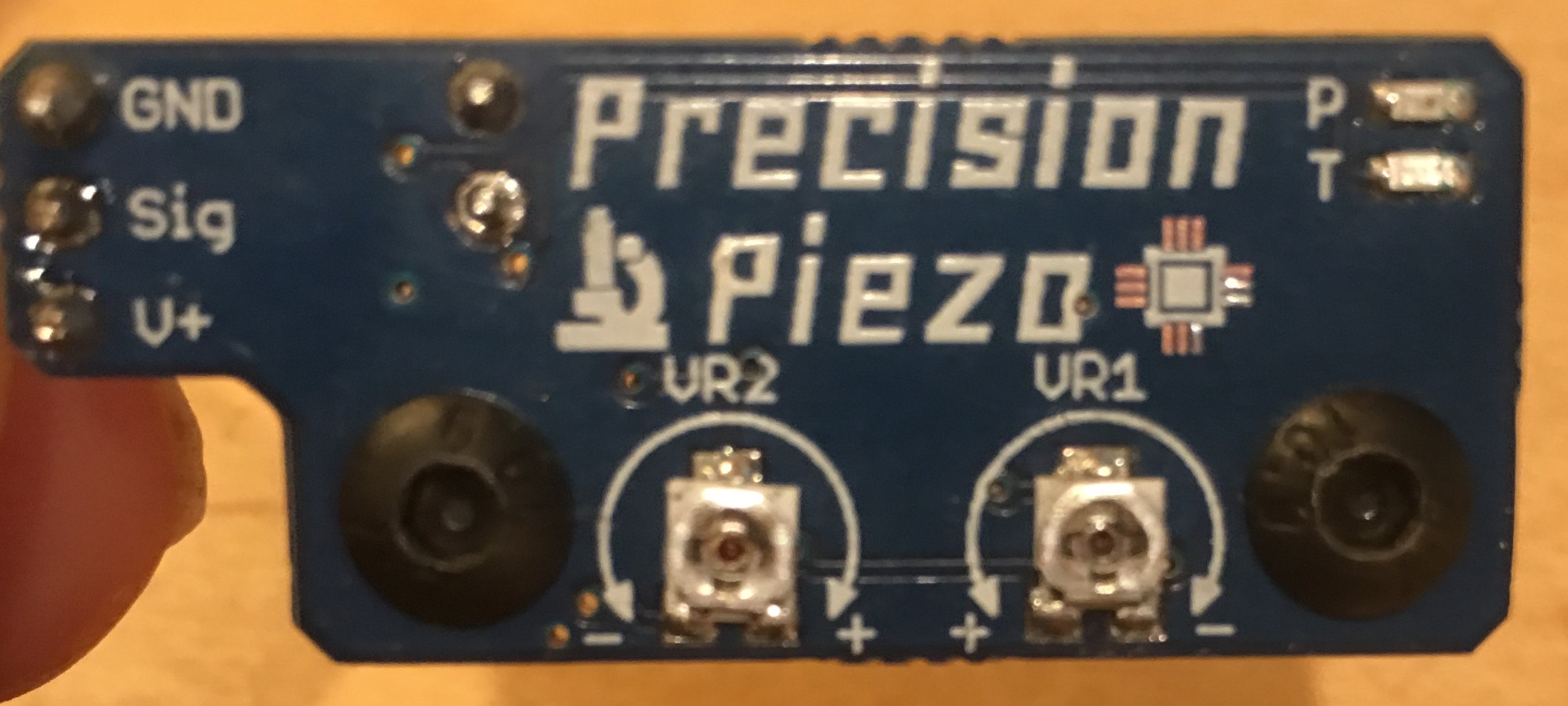
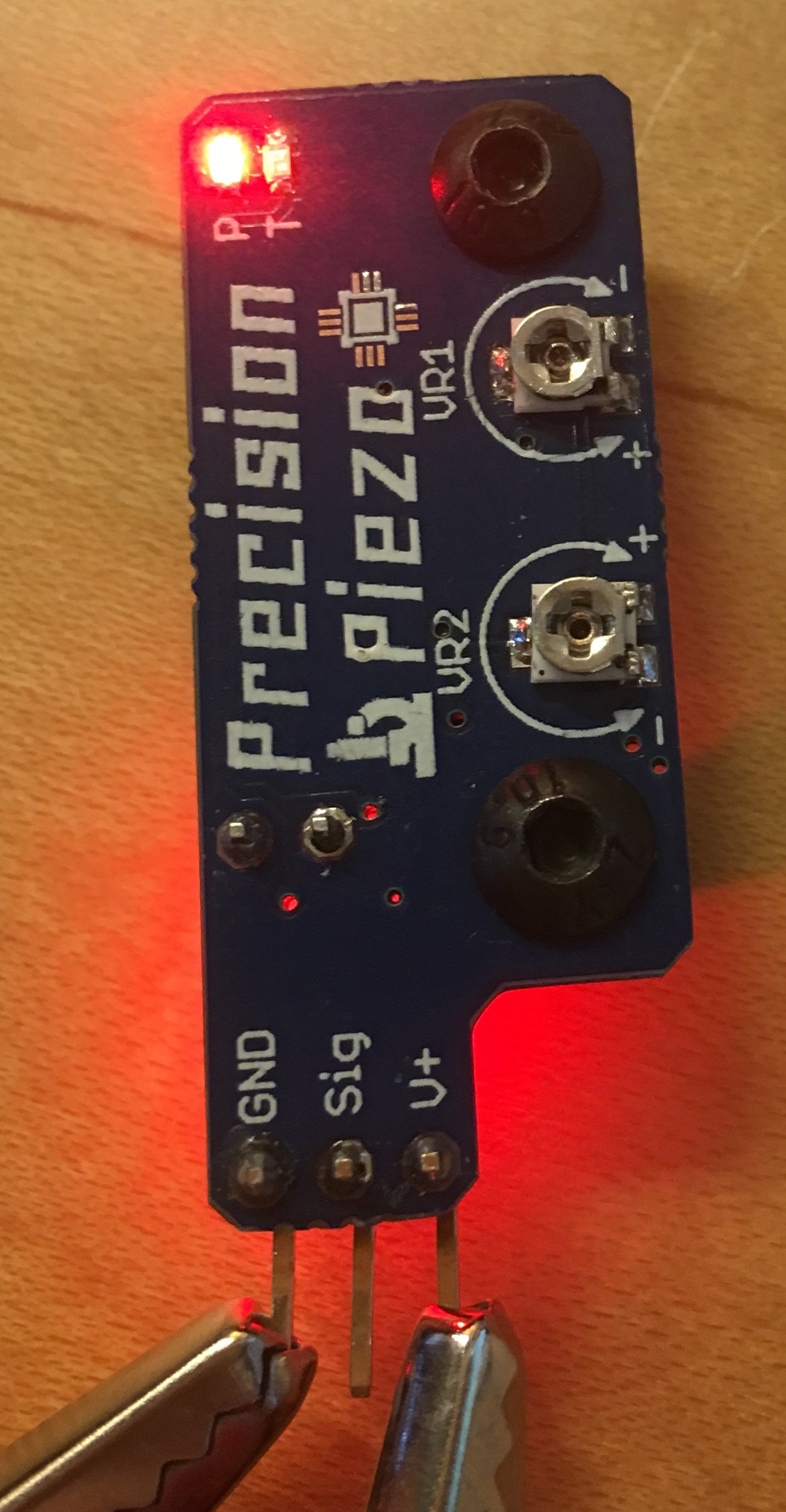
I will be the first to say that I am probably doing something wrong. Modern, surface mount, boards are very rarely incorrect. However... I can't seem to get my Precision Piezo board working. First, let me verify it is a "V2". It has mounting holes. It has LEDs on both sides. It has a 3-pin connector for Gnd Sig V+ on a part of the blue board that is a bit "L" shaped as compared to the rest of the board. V2, correct?
Now, the real problem: I can't get VR1 set. The manual suggests setting it to "0.4MΩ", which is 400KΩ the way my DVM is going to display it. However, I can't get the physical potentiometer to anything over about 198KΩ. This is with everything unplugged from the board, and hooked up to the 'bottom' pin for the Piezo, and the 'center' pin for the pot. I've tried both the solder pad at the 'top' of the pot, and the metal adjuster ring itself. Identical results.
Furthermore, looking at the circuit diagram, I see that one end of the physical potentiometer is not connected. Therefore, I should be able to put my DVM on the two "end" connectors, physically on the bottom of the pot, and read 1MΩ (+/- 20%). Instead, I read 198KΩ. Like it was a 200K pot, within +/- 1%.
So... a couple of questions:
What should a DVM read when touching the two bottom-most pins on VR1?
Is there any possibility that some boards shipped with the wrong pot? I bought this plenty long ago enough that warranty is no longer valid... but I'd be happy to fix it myself if it is just the pot.
|
Re: Precision Piezo Z-probe Now available. March 09, 2018 05:51PM |
Registered: 6 years ago Posts: 54 |
|
Re: Precision Piezo Z-probe Now available. March 09, 2018 05:54PM |
Registered: 9 years ago Posts: 487 |
Hi Danal,
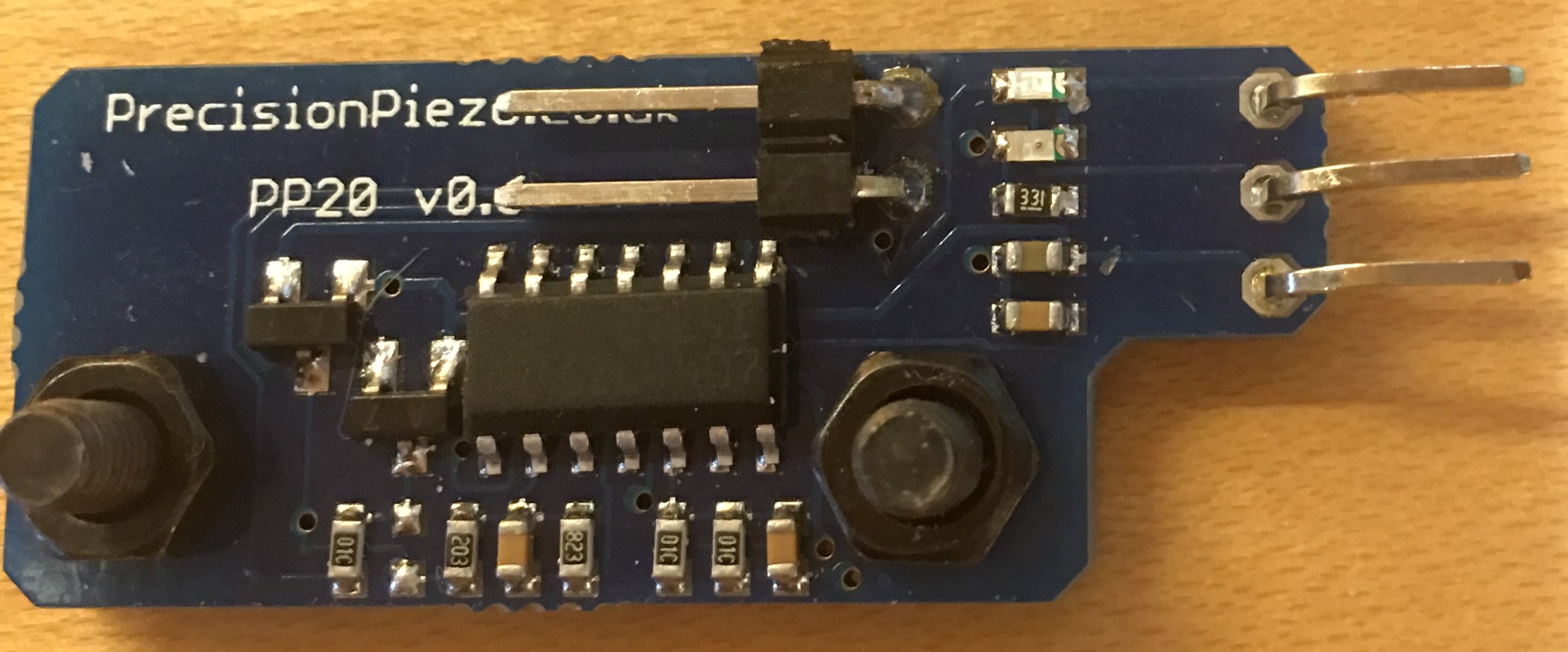
Your board should have a model number on it, what you have is a PP20 board so the model number is on the back where the piezo plugs in, it's either a v0.6 or a v0.7.
The simplest way to measure the resistance of VR1 is to measure the resistance between the two piezo terminals and as you say it should go up to around 1M, it certainly should read 1M between the two sides of the pot. We did have a couple of cases boards being returned with incorrect values of VR1 and we tracked it down to a couple of rogue 220K pots in a reel of 1M pots, the timing fits about right too. I'm happy to send you out a replacement board if you'd like or I'll help you fix it yourself if you'd prefer.
Idris
{Precision Piezo} Accurate, repeatable, versatile z-probe plus piezo discs, endstop cables, pt100, 50w heaters.
|
Re: Precision Piezo Z-probe Now available. March 09, 2018 07:14PM |
Registered: 6 years ago Posts: 5 |
It does say PP20 V0.6 on the back. I did order it directly from PP. I could be wrong about the LEDs on both sides...
Order No. 10179 Placed on Nov 8, 2017
If you did have a few 220K go out, that's probably it. Given the potential issues of getting a single pot, that fits the footprint, etc. a new board would be ideal. And, it is very kind of you, given the time that has passed.
Danal Estes
65 Hidden Valley Airpark
Shady Shores, TX 76208
|
Re: Precision Piezo Z-probe Now available. March 09, 2018 07:24PM |
Registered: 6 years ago Posts: 5 |
|
Re: Precision Piezo Z-probe Now available. March 10, 2018 03:27AM |
Registered: 9 years ago Posts: 487 |
Only PP20 pcbs have components on both sides and there is no v2 pp20... yet.
I'll get a replacement pcb sent out to you asap.
Idris
{Precision Piezo} Accurate, repeatable, versatile z-probe plus piezo discs, endstop cables, pt100, 50w heaters.
I'll get a replacement pcb sent out to you asap.
Idris
{Precision Piezo} Accurate, repeatable, versatile z-probe plus piezo discs, endstop cables, pt100, 50w heaters.
|
Re: Precision Piezo Z-probe Now available. March 10, 2018 03:39AM |
Registered: 8 years ago Posts: 5,232 |
Here's a summary of my findings about the universal PP with three 20mm underbed Piezos:
In general it works very nice, but the PETG sliders of my Compact Carrier Delta were to noisy ( stiction ) that they would cause a trigger anytime the steppers move.
I added a bridge rectifier, to cut off some of the noise ( like MKSA predicted ) and it got better. I could finally probe the bed with reduced acceleration and probing speed.
But the real brakethrough came with new Delrin slider and beefed up carriers. Now I get deviation results around 0.02 which is in the ball park of my other Delta with linear rails and Smart effector.
Two sidenotes about the bridge rectifier:
1st: If you use the PP as pressure sensor, you get a trigger signal when pushing and when releasing the pressure. But the usual bed.g probe session releases the pressure within the 2.5ms trigger time, so no worries here.
2nd: When using three Piezos, you either need a rectifier for each Piezo, or you have to attach all three Piezos in the same polarity. The rectifier then works as noise reducer only.
Another note about underbed sensors. They work reliable at PLA bed temp, but 90°C or more is a no-no. You have to probe before heating up.
Edited 1 time(s). Last edit at 03/10/2018 03:42AM by o_lampe.
In general it works very nice, but the PETG sliders of my Compact Carrier Delta were to noisy ( stiction ) that they would cause a trigger anytime the steppers move.
I added a bridge rectifier, to cut off some of the noise ( like MKSA predicted
) and it got better. I could finally probe the bed with reduced acceleration and probing speed. But the real brakethrough came with new Delrin slider and beefed up carriers. Now I get deviation results around 0.02 which is in the ball park of my other Delta with linear rails and Smart effector.
Two sidenotes about the bridge rectifier:
1st: If you use the PP as pressure sensor, you get a trigger signal when pushing and when releasing the pressure. But the usual bed.g probe session releases the pressure within the 2.5ms trigger time, so no worries here.
2nd: When using three Piezos, you either need a rectifier for each Piezo, or you have to attach all three Piezos in the same polarity. The rectifier then works as noise reducer only.
Another note about underbed sensors. They work reliable at PLA bed temp, but 90°C or more is a no-no. You have to probe before heating up.
Edited 1 time(s). Last edit at 03/10/2018 03:42AM by o_lampe.
|
Re: Precision Piezo Z-probe Now available. March 10, 2018 08:24AM |
Registered: 6 years ago Posts: 5 |
|
Re: Precision Piezo Z-probe Now available. March 10, 2018 08:54AM |
Registered: 8 years ago Posts: 1,671 |
Anyone noticed that when motors are powered they create some vibration, this vibration is transferred to the bed on contact, maybe it's just my printer ? ... but I just used this to level my bed and it worked great, would the piezo's be able to pick this up & use it, or some other sensor?
|
Re: Precision Piezo Z-probe Now available. March 10, 2018 09:00AM |
Registered: 6 years ago Posts: 5 |
So,
i am using PP in an underbed configuration, 3 20mm piezos. So many problems that i am designing a new housing to move this on the effector (i have a delta)
Underbed has lots of issues: first the mass of the bed itself, that keeping the pressure on the piezos forces you to decrease the sensibility, then vibration from the motors that on the bed is a lot more perceivable then the heated bed has cables that offset some of the force.
Do not mount under the bed.
Great convenience, a nightmare to calibrate.
|
Re: Precision Piezo Z-probe Now available. March 10, 2018 10:33AM |
Registered: 6 years ago Posts: 54 |
Diego:
If I may comment on your last 2 lines. I do not have a delta!
I have tested all sizes of the piezo sensors under bed and found that all work with the appropriate tuning. The sizes ranged from the 12mm to the gigantic 41mm. I only used one sensor mounted on the carriage holding the print bed surface at a time, although all 4 were installed, only one was tested at a time. My findings are, considering availability of real estate on your printer: size of the piezo does NOT matter! Choose 1 and go for it. I have had the opportunity to test the PP new model hot end product and found it exceptional. So am torn between hot end vs under bed.
So last comment on ease of tuning, My thoughts EASEY!
My test results have been shared with Simon/ Idris and am
|
Re: Precision Piezo Z-probe Now available. March 10, 2018 11:14AM |
Registered: 6 years ago Posts: 60 |
I am using a 4 piezo (2+2 noise canceling) setup and find it working quite well on my coreXY (gantry moves in Z)
Underbed on a moving Z gantry is not an option, a carriage based/hotend based solution would be better in that case.
I found that tweaking my underbed setup was not challenging at all once I added the noise canceling piezos.
The 20 mm piezo sits in a foot made from TPU and it is very sensitive.
I'll post a picture of the real life setup once it has finished printing
This is an ABS only printer (enclosed, 320 W bed heats the air to about 45deg), I found no problems with heat regarding the piezos
Edited 1 time(s). Last edit at 03/10/2018 11:16AM by whosrdaddy.
Underbed on a moving Z gantry is not an option, a carriage based/hotend based solution would be better in that case.
I found that tweaking my underbed setup was not challenging at all once I added the noise canceling piezos.
The 20 mm piezo sits in a foot made from TPU and it is very sensitive.

I'll post a picture of the real life setup once it has finished printing
This is an ABS only printer (enclosed, 320 W bed heats the air to about 45deg), I found no problems with heat regarding the piezos
Edited 1 time(s). Last edit at 03/10/2018 11:16AM by whosrdaddy.
|
Re: Precision Piezo Z-probe Now available. March 10, 2018 11:30AM |
Registered: 8 years ago Posts: 3,525 |
I think we have two cases where underbed works well:
1) delta, the stationary bed results in the least issues with false triggering you can use 1-6 Piezos depending on how you want to set it up.
2) using one piezo under the bed the way Stef/Chowa uses it. This works more in "microphone" mode (at least I presume it does). EDIT seems it is not using microphone type sensing but instead a single piezo centrally located which is put under tension by the bed adjusters at the corners.
There is one case which should work well and that's the i3 style machine with y moving bed. Using delay before probing means any ringing from the bed stops before probing begins.
There is one case which is problematic and that is corexy, the variant where the bed moves in z, rather than where the gantry moves in z this should work well, the issue is when the bed lifts to make contact with the nozzle it squeezes or compresses Piezos placed in the bed mounts. As a result you need low sensitivity even with very low acceleration and 0 jerk but the low sensitivity makes for poor triggering. I haven't had chance yet to try a noise cancelling setup or a rectifier but I suspect in this case it won't help much as its the inertia of the bed that causes the problem (my corexy has a belt driven bed and is quite smooth).
Edited 1 time(s). Last edit at 03/10/2018 12:51PM by DjDemonD.
Simon Khoury
Co-founder of [www.precisionpiezo.co.uk] Accurate, repeatable, versatile Z-Probes
Published:Inventions
|
Re: Precision Piezo Z-probe Now available. March 10, 2018 12:13PM |
Registered: 6 years ago Posts: 54 |
Having the under bed piezo, I am not sure if the label "MICROPHONE" mode applies as the print bed is adjusted to tightly squish the plunger of the piezo. So whatever vibration from the nozzle contacting the print bed is mechanical or audio I can't say. For sure it works well! I also must say that there is an insulating blanket of a black foam (assume neoprine) covered with an aluminium foil. So when preloaded, the foam is squished. In any case the new product hot end PP20? Is exceptional in its mounting regidity and performance, quite suitable for those needing an hot end sensor.
Great work Simon/Idris and your team.
Stef
Great work Simon/Idris and your team.
Stef
|
Re: Precision Piezo Z-probe Now available. March 10, 2018 12:45PM |
Registered: 8 years ago Posts: 3,525 |
Thanks, sorry if I've misinterpreted how you are using it. So you have 3/4 corner screws/adjusters and a central piezo bed mount?
Simon Khoury
Co-founder of [www.precisionpiezo.co.uk] Accurate, repeatable, versatile Z-Probes
Published:Inventions
Simon Khoury
Co-founder of [www.precisionpiezo.co.uk] Accurate, repeatable, versatile Z-Probes
Published:Inventions
|
Re: Precision Piezo Z-probe Now available. March 10, 2018 01:20PM |
Registered: 6 years ago Posts: 54 |
Not sure myself which mode is being sensed.
The bed uses 4 spring mounted adjusters
With the piezo s mounted beneath the build plate .
On an x shaped carriage on which are mounted the 4 different size piezos. I did post photos previously. I do have a small microphone that could be mounted on the carriage to see what the resonant frequency is.
Stef
Edited 1 time(s). Last edit at 03/10/2018 01:30PM by Chowa.
|
Re: Precision Piezo Z-probe Now available. March 11, 2018 03:49AM |
Registered: 6 years ago Posts: 25 |
So i finally got the pcb (took 2 weeks in EU, royal mail is as bad as it gets). Stickers all over, pin out changed, check wiring. PCB 1.1 looks nothing like on the website. There is only one adjustment screw. Website does not contain info on this or pinout and i am left stranded guessing if the pinout markings are wrong or something else.
|
Re: Precision Piezo Z-probe Now available. March 11, 2018 05:46AM |
Registered: 8 years ago Posts: 3,525 |
Sorry it took a while to arrive we have a choice with shipping of cheap and slow or very expensive and quick.
What stickers?
Yes we have changed the pinnout to make it match a standard endstop cable so it's red, black, green (vcc, GND, TRG).
I think documentation might be lagging behind hardware development I apologise if documentation isn't quite there yet but I can assure you the changes to make the product better. We've done away with the sensitivity pot as it wasn't necessary, implemented easy tuning by making the tuning range on the single pot wider and less knife edged, and changed the pins to make standard endstop cables work without having to swap pins.
We will get the docs up together.
Simon Khoury
Co-founder of [www.precisionpiezo.co.uk] Accurate, repeatable, versatile Z-Probes
Published:Inventions
|
Re: Precision Piezo Z-probe Now available. March 11, 2018 05:55AM |
Registered: 9 years ago Posts: 487 |
Hi agniusm,
Version 1.1 is a significant improvement over the earlier versions, the removal of one of the adjustments and other changes make tuning significantly easier. You will find the manual with wiring and tuning instructions here
I put a sticker over the pins to ensure that anyone upgrading from an earlier version is aware that the pinout has changed and to check their wiring before plugging in the new board and risking breaking something.
Idris
Edited 1 time(s). Last edit at 03/11/2018 05:59AM by Moriquendi.
{Precision Piezo} Accurate, repeatable, versatile z-probe plus piezo discs, endstop cables, pt100, 50w heaters.
|
Re: Precision Piezo Z-probe Now available. March 11, 2018 06:29AM |
Registered: 6 years ago Posts: 25 |
Understood. All is good, just confusion. The pins are marked so i assumed marking are wrong .
Regarding shipping, I post stuff to US and its there in 10 days and thats cheapest option from postal service. It probably how RM works. I remember same when living in UK.
Is there a guide for wiring to duet? I found firmware setup and kind off remember somewhere written to wire to Z endstop but not sure now
|
Re: Precision Piezo Z-probe Now available. March 11, 2018 06:36AM |
Registered: 8 years ago Posts: 3,525 |
We leave you to chose how to wire the system to your board otherwise we would be liable for miswiring etc..
So take a look at the duet documents [duet3d.dozuki.com]
There is 3.3v,gnd and signal. The pin that can be left unconnected on the duet is mod.
Edited 1 time(s). Last edit at 03/11/2018 06:42AM by DjDemonD.
Simon Khoury
Co-founder of [www.precisionpiezo.co.uk] Accurate, repeatable, versatile Z-Probes
Published:Inventions
|
Re: Precision Piezo Z-probe Now available. March 11, 2018 06:52AM |
Registered: 6 years ago Posts: 25 |
|
Re: Precision Piezo Z-probe Now available. March 11, 2018 08:06AM |
Registered: 6 years ago Posts: 25 |
Ok. Got it connected. I have red light and when i tap the nozzle blue one comes up. Does that pot controlls sensitivity?
I might have a problem with my system and need clarification. My extruder is pulled on a bracket and not the bearing itself which will trigger piezo while traveling on x. How the probe is engaged? If it will stop at designated spot and then engage it wont be a problem as x would be still. Thanks
I might have a problem with my system and need clarification. My extruder is pulled on a bracket and not the bearing itself which will trigger piezo while traveling on x. How the probe is engaged? If it will stop at designated spot and then engage it wont be a problem as x would be still. Thanks
|
Re: Precision Piezo Z-probe Now available. March 11, 2018 08:17AM |
Registered: 8 years ago Posts: 3,525 |
Yes sorry its z probe connector. X and y movements will trigger the probe but this doesn't matter when actually probing as the x and y movements stop before the probing dive. You have a pause configured in (M558 R) so this allows the frame/axes to settle before probing.
RRF does not monitor the probe unless actually probing. We toyed with the idea of using it to detect rough layers and crashes but haven't done it yet
Edited 2 time(s). Last edit at 03/11/2018 09:01AM by DjDemonD.
Simon Khoury
Co-founder of [www.precisionpiezo.co.uk] Accurate, repeatable, versatile Z-Probes
Published:Inventions
|
Re: Precision Piezo Z-probe Now available. March 11, 2018 02:57PM |
Registered: 7 years ago Posts: 257 |
|
Re: Precision Piezo Z-probe Now available. March 11, 2018 03:06PM |
Registered: 8 years ago Posts: 3,525 |
If theres no mount on thingiverse then that sounds like an awesome idea. The prometheus is a groovemount so shouldn't be too hard to adapt or fit into the existing Piezo20 design.
Simon Khoury
Co-founder of [www.precisionpiezo.co.uk] Accurate, repeatable, versatile Z-Probes
Published:Inventions
Simon Khoury
Co-founder of [www.precisionpiezo.co.uk] Accurate, repeatable, versatile Z-Probes
Published:Inventions
|
Re: Precision Piezo Z-probe Now available. March 11, 2018 06:36PM |
Registered: 6 years ago Posts: 60 |
Here is my underbed setup:
you can see the 2 "microphone" piezos taped to the frame and the 2 sensing piezos fitted inside the TPU feet.
Each pair of piezos are wired together (+ connected to - and vice versa), this means that they have to be oriented in the same way.
Here is a small video so you can see how it works:
[youtu.be]
As you can see, it won't trigger if I tap the surrounding frame, only tapping the bed triggers the piezo.
Without the pickup piezo's I was getting false triggers from the Z motors causing vibration to the frame.
Edited 1 time(s). Last edit at 03/11/2018 06:36PM by whosrdaddy.


Sorry, only registered users may post in this forum.