3 points levelling system
Posted by Tinchus
|
3 points levelling system December 21, 2017 09:02PM |
Registered: 8 years ago Posts: 155 |
I have a prusa i3. As all of them, it come wth a bed atach to 4 points. To elvel, you adjust those 4 screws. Along time I have experimented different levelling methods: 4 points with springs, hardest springs, removeing the springs, etc; all methods have advantages and disadvantages but all of them are quite time consuming and tiring.
I always wondered about the 3 point levelling method. SO now I dedicated some time reading about it.
Digital dentist wrote some nice articles about it. So I decided to give it a try.
I did a quick modification to my bed, I jst added a piece of metal into the bed support, and that easy I got the point to atach th mk3 aluminium heated bed, that has already a hole prepare for useing a 3 point levelling system.
I followed the steps described by digital dentist (https://drmrehorst.blogspot.com.ar/2017/07/3-point-print-bed-leveling-vs-4-point.html), and other ones. I failed
Any method I try, I get the same resultL the lower left corner allways ends up with a bigger gap between noozle tip and the bed. All the other areas in the bed are really nice levelled!!! in fact really much better and easy than with the 4 point levelling system (useing 4 screws always gave me as result some kind of torsion in the alumiun, giving as result some kind of warping up or down in the center...)
The gap I get in this lower left corner is 0.3 mm bigger than in any other area in the bed. So I though that the bed itself mught be twisted? I checked wth a square ruler but it seems really flat.
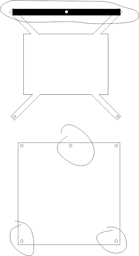
Any ideas why is this happening? I have ataches an image showing the metal peice adition, adn the 3 holes I use for the 3 point levelling method.
Thanks in advvance
I always wondered about the 3 point levelling method. SO now I dedicated some time reading about it.
Digital dentist wrote some nice articles about it. So I decided to give it a try.
I did a quick modification to my bed, I jst added a piece of metal into the bed support, and that easy I got the point to atach th mk3 aluminium heated bed, that has already a hole prepare for useing a 3 point levelling system.
I followed the steps described by digital dentist (https://drmrehorst.blogspot.com.ar/2017/07/3-point-print-bed-leveling-vs-4-point.html), and other ones. I failed
Any method I try, I get the same resultL the lower left corner allways ends up with a bigger gap between noozle tip and the bed. All the other areas in the bed are really nice levelled!!! in fact really much better and easy than with the 4 point levelling system (useing 4 screws always gave me as result some kind of torsion in the alumiun, giving as result some kind of warping up or down in the center...)
The gap I get in this lower left corner is 0.3 mm bigger than in any other area in the bed. So I though that the bed itself mught be twisted? I checked wth a square ruler but it seems really flat.
Any ideas why is this happening? I have ataches an image showing the metal peice adition, adn the 3 holes I use for the 3 point levelling method.
Thanks in advvance
|
Re: 3 points levelling system December 21, 2017 09:22PM |
Registered: 11 years ago Posts: 5,780 |
The Y axis rails may not be parallel. If the rails aren't parallel, even if your bed is flat, you won't be able to get it level. If the printer is sitting on a flat surface, try putting a spacer under each end of each of the Y axis rails. They should all be at exactly the same height.
Ultra MegaMax Dominator 3D printer: [drmrehorst.blogspot.com]
Ultra MegaMax Dominator 3D printer: [drmrehorst.blogspot.com]
|
Re: 3 points levelling system December 21, 2017 09:33PM |
Registered: 8 years ago Posts: 155 |
|
Re: 3 points levelling system December 21, 2017 10:23PM |
Registered: 11 years ago Posts: 5,780 |
The guide rails define the XY plane in the printer. The bed is level when it is parallel to the XY plane defined by the guide rails If the rails aren't parallel, there's no XY plane to set the bed parallel to.
The bed moves from one end of the rails to the other. If they aren't parallel the bed will twist as it moves along them. Adjusting the bed level can't compensate for guide rails that aren't parallel.
Ultra MegaMax Dominator 3D printer: [drmrehorst.blogspot.com]
The bed moves from one end of the rails to the other. If they aren't parallel the bed will twist as it moves along them. Adjusting the bed level can't compensate for guide rails that aren't parallel.
Ultra MegaMax Dominator 3D printer: [drmrehorst.blogspot.com]
|
Re: 3 points levelling system December 22, 2017 06:29AM |
Registered: 8 years ago Posts: 155 |
mmm ok... so I guess that tis is why 4 points levelling is used instead of 3? 3 point levelling is somehow the correct... but asumes a lot of things in real world would be too dificult to have...
Im my case, I have measured, the Y smooth roods have a difference in height og 0.4mm from end to end... in terms of real world that would be considered parallel...
IF that small difference avoids the user to use a 3 points levelling method... that will reduce a ot of other mods, like for example antivibration pads...if you put a pad under each Y end, some of the pads will bend a little more than the other...jsut as an example
I guess 3 points levelling is something meant to be used for super exact 3d printers
|
Re: 3 points levelling system December 22, 2017 07:45AM |
Registered: 11 years ago Posts: 5,780 |
No, 4 point "leveling": is used because the "designer" didn't think about or didn't understand the problem. 4 point leveling doesn't compensate for non parallel rails either.
The real world you're in is 3D printing. When you're trying to print layers that are 0.2 mm thick, the guide rails being off by 0.4 mm is 2 layer thicknesses. That's pretty awful- you're lucky that the sloppy bearings allow the bed to slide from one end to the other with that much misalignment. If the designer really knew what he was doing, he would have made the guide rail positioners adjustable so that the rails could be made parallel instead of forcing the user to invent some way of shimming them. Let me guess, the guide rails are attached to the frame using 3D printed parts? It may be that the printer's frame is flexing because it isn't sitting on a flat surface. Antivibration pads under the printer may allow the frame to twist, throwing the guide rails out of parallel. I'd start by getting rid of the pads and check it again.
3D printer operation is based on a lot of assumptions. The most fundamental assumption is that the guide rails are parallel and the axes defined by them are orthogonal. That's where you start fixing a printer that has problems. For a lot of printers with flexible frames, one underlying assumption is that the printer will be sitting on a flat surface when it is operated- the table or desk becomes a critical part of the printer.
Ultra MegaMax Dominator 3D printer: [drmrehorst.blogspot.com]
|
Re: 3 points levelling system December 22, 2017 08:29AM |
Registered: 8 years ago Posts: 3,525 |
Tinchus how sure are you that your bed isn't bent? I have a 3mm rolled aluminium bed which always has one low corner, it's not a levelling issue I have manual 3 point levelling screws. Once I've done that I use mesh levelling with fade off, so it doesn't really make any difference, plus I print away from that corner unless I have to fill the build plate.
Edited 1 time(s). Last edit at 12/22/2017 08:30AM by DjDemonD.
Simon Khoury
Co-founder of [www.precisionpiezo.co.uk] Accurate, repeatable, versatile Z-Probes
Published:Inventions
Edited 1 time(s). Last edit at 12/22/2017 08:30AM by DjDemonD.
Simon Khoury
Co-founder of [www.precisionpiezo.co.uk] Accurate, repeatable, versatile Z-Probes
Published:Inventions
|
Re: 3 points levelling system December 22, 2017 08:48AM |
Registered: 8 years ago Posts: 155 |
OK, DD, may be Im not understanding what you mean by parallel rails. My printer is a prusa i3. Are the smooth Y rods parallel between them? yes. If I measure the height inthe beginning og 1 of the smooth rods and the end of it, there is a difference of 0.4 mm. That means... yes, it is not parallel to the ground (the ground is levelled). The Z frame is squared to the X and Y axis. So, why does it matter if the rails are parallel or not to the ground? as far as 3 axis are square between them .
It is obvious that there must be somehting out of aligment and that makes the 3 point levelling to not work.
The funny thing is: as you explained in the article, the 4 points method ebnds/twist the bed or frame. But... I can definitly say that I can perfectly level my bed useing the 4 points method, and I print 0.15 first layers with no problem at all, and I can print ABS objects of 20X20 cms (the entire bed) without suffering adhesion problems.
Im turning to, or at least trying, the 3 pont system because the 4 points has a disadvantage for me: I have to re level the bed every 20/30 hs of printing. I was looking a way to improve this and that is how I found you and the 3 point method.
So, You are right, but Im right too: 3 points method is only usefull for super exaxtly built machines with super flat beds. The 4 ppoint method somehow compesate through twisting/flexing the problem in lower machines
DjDemon: I know my bed is flat, because I used a square dig rule to test it. It is flat, more than enough to not make what Im seeing . Your description looks exactly like mine: 1 corner looks bent... actually, have you checked really that your bed is bent or you though that by looking the levelling differences? If you did... remove the bed and check how flat it is, probabl you are looking exactly what Im. Useing 3 points gives me a really quick and awesome level through the entire bed BUT in the lower left corner, getting to that area the gap between noozle and bed start to grow and grow till makeing a gap og 0.3 mm. I though the bed it was bent... but it was not
And yes. a way ti solve this would be to use autolevelling. The problem with that is that the top of the model wouldnt be flat, it will be a copy of the non flat surface it was built in.
Edited 2 time(s). Last edit at 12/22/2017 08:52AM by Tinchus.
|
Re: 3 points levelling system December 22, 2017 09:34AM |
Registered: 11 years ago Posts: 5,780 |
When I said check for parallel guide rails, I meant make sure that the rails are parallel to each other. If both rails are higher at one end than the other by the same amount, they may be parallel. When you said it was off by 0.4 mm, I thought you meant one rail was higher at one end by 0.4 mm. If the rails are parallel and 3 point leveling isn't leveling the bed, then the bed is not flat. If the bed isn't flat, what does it mean for it to be "level"?
Check the bed for flatness by putting the edge of a steel ruler on it and see if there are any gaps.
Ultra MegaMax Dominator 3D printer: [drmrehorst.blogspot.com]
Check the bed for flatness by putting the edge of a steel ruler on it and see if there are any gaps.
Ultra MegaMax Dominator 3D printer: [drmrehorst.blogspot.com]
|
Re: 3 points levelling system December 22, 2017 09:49AM |
Registered: 8 years ago Posts: 3,525 |
Yes mine is low in the front left corner too. But I think it's the bed as it's worse heated than cold, it's better if I put a sheet of glass on top of it. I've been meaning to get a tooling plate for this machine for a while and get rid of the problem once and for all.
Autolevelling (flat bed on an angle) would not be the answer, grid levelling (non flat bed, possibly angled or not) with compensation fade out means only the surface touching the bed needs to be uneven or tilted, and only for x mm(I use 10mm but you could set 3 or other similar small number). However I only know for sure one firmware which can do this.
Perhaps using 4 point levelling was bending your bent bed straight?
Simon Khoury
Co-founder of [www.precisionpiezo.co.uk] Accurate, repeatable, versatile Z-Probes
Published:Inventions
|
Re: 3 points levelling system December 22, 2017 02:09PM |
Registered: 8 years ago Posts: 155 |
Im on stuborn mode now jajajaj. I will figure this out...
Ok, I have removed the antivibration pads. Printer now is on its table wich is flat and levelled. I have checked again if Z rails are parallel, this time useing an asimeto digital caliper just to be sure my measurements are precise. And yes, the are PERFECT parallel: 34.61 mm in each end of them (I got 34.63 mm in 1 of them... but that is 0.02 mm of differences wich is inside the error margin, and when repeated measurements I got readings between 34.61 and 34.63 ... so...
I re checked bed flatness.. it is flat. I can see bumps in the surface, and putting a steel ruler I can see it is flat, and in those bumps U can see, I can measure useing a gage something between 0.05 and 0.1 mm. In fact, what youn see in the picture, in the right, there is a brand new mk3 bed, I bought it this morning just to be sure my bed was not bent by the 4 points method in the past. And I got the same results while levelling.
So now I tried 3 points levelling again. I start setting the reference screw as in Digital dentist instructions. I set there a gap of 0.1 mm between noozle tip and the bed (measured with a gage, I dont use the paper method). The I move to the pitch screw and set there a 0.1 mm gap too (when I do this, the gap at the reference screw decreases a little, to 0.05 mm). If I move now the x carriage between these 2 screws, I can perfectly see that the line between them is really and nicely levelled, showing that the bed is not warped, at least in this area?
Then I go to the roll screw and set 0.1 mm gap there too. I check now the pitch screw again and did a very very small adjustment, then another very small adjustment in the roll screw again. After this if I check levelness all around the bed is really beatiful (the most beatiful is that doing this take 3 minutes!!!!)> in all places I get a gap between noozle tip and bed of something between 0.05 and 0.1 mm BUT in the top left corner of the picture, right near the corner (no further than 3 or 4cms away) the gap is of 0.25 EXACTLY (measure with a gage). Im preious post I reported this gap to be in the lower left corner. That seems to change depending on the steps I take to do the levelling. If I follow the step described by digital dentist, That bigger gaps moves to the top left corner. If I follow another steps described in other sites, that gap appear in the lowest left corner...
Only Idea comeing to my mind: The roll screw, is supported on a piece of metal I builted in order to get this mod (sonce prusas uses only 4 point method). The Aluminium bed comes with a hole in the exact center in order to be able to use it with a 3 point method too, so that hole I know is exactly in center. Question is: if the hole in the piece of metal is not exactly in the center (I measured it and can be may be 0.5 mm out of center), could be creating some trouble with the 3 points method?

|
Re: 3 points levelling system December 23, 2017 01:52AM |
Registered: 6 years ago Posts: 1,007 |
|
Re: 3 points levelling system December 23, 2017 04:50AM |
Registered: 8 years ago Posts: 155 |
|
Re: 3 points levelling system December 23, 2017 05:20AM |
Registered: 12 years ago Posts: 1,450 |
I think that what may be going on is that the four legs of the "squashed frog" are flexible and the metal you have added is also flexible. The normal requirement of the spring leveling is that the mount of the adjusting screws is firm and that the bed only moves when the load exceeds the upward push on the spring while your added metal part just added unwanted flexibility. My guess is that Prusa printers found a system that worked - the legs of the carriage bent rather than bending the bed. There may be other reasons that the four point leveling remains popular - maybe it helps with anti vibration, dynamic systems can be complicated and anti-intuitive sometimes.
Just a passing thought, is there anything else that may be holding a part of the bed down? Bed heater wires come to mind.
Mike
Just a passing thought, is there anything else that may be holding a part of the bed down? Bed heater wires come to mind.
Mike
|
Re: 3 points levelling system December 23, 2017 06:16AM |
Registered: 6 years ago Posts: 1,007 |
Quote
leadinglights
I think that what may be going on is that the four legs of the "squashed frog" are flexible and the metal you have added is also flexible. The normal requirement of the spring leveling is that the mount of the adjusting screws is firm and that the bed only moves when the load exceeds the upward push on the spring while your added metal part just added unwanted flexibility. My guess is that Prusa printers found a system that worked - the legs of the carriage bent rather than bending the bed. There may be other reasons that the four point leveling remains popular - maybe it helps with anti vibration, dynamic systems can be complicated and anti-intuitive sometimes.
Just a passing thought, is there anything else that may be holding a part of the bed down? Bed heater wires come to mind.
Mike
Four points is popular because people simply don't think past the fact that as it has 4 corners, therefore it needs 4 post/screws ! Here one can see the ignorance about basic spatial geometry: // definition, plane definition etc...
Edited 1 time(s). Last edit at 12/23/2017 06:22AM by MKSA.
"A comical prototype doesn't mean a dumb idea is possible" (Thunderf00t)
|
Re: 3 points levelling system December 23, 2017 06:30AM |
Registered: 12 years ago Posts: 1,450 |
|
Re: 3 points levelling system December 23, 2017 07:36AM |
Registered: 6 years ago Posts: 1,007 |
Quote
leadinglights
Quote
MKSA
Four points is popular because people simply don't think past the fact that as it has 4 corners, therefore it needs 4 post/screws ........
I find it difficult to think that Joseph Prusa would have used the four point or the squashed frog without reason.
Mike
He also uses two motors for the Z axis, hold the bearings with tie wraps, the frame is rather flimsy .... Fact; the Prusa is far from mechanically sound but a good enough solution to provide hobbyist with a cheap 3D beginner's machine.
Easy improvements are possible but Chinese copies and some amateurs exacerbate its shortcomings, so plenty of room to do worse

Indeed, engineers can make mistakes but often have to make them to please the bean-counters
Again the key is "good enough to do the job"
Edited 2 time(s). Last edit at 12/23/2017 07:38AM by MKSA.
"A comical prototype doesn't mean a dumb idea is possible" (Thunderf00t)
|
Re: 3 points levelling system December 23, 2017 07:53AM |
Registered: 8 years ago Posts: 3,525 |
I agree, I started with an i3 1.5 which did print stuff despite its shortcomings, sold it built some much more precise and less "compromise" machines now I'd like a mk3. Partly as it closes the circle and partly as they (mk2s anyway) get great reviews.
What you build yourself and what you can make thousands and sell are never the same thing.
Simon Khoury
Co-founder of [www.precisionpiezo.co.uk] Accurate, repeatable, versatile Z-Probes
Published:Inventions
What you build yourself and what you can make thousands and sell are never the same thing.
Simon Khoury
Co-founder of [www.precisionpiezo.co.uk] Accurate, repeatable, versatile Z-Probes
Published:Inventions
|
Re: 3 points levelling system December 23, 2017 09:12AM |
Registered: 7 years ago Posts: 507 |
I'm personally waiting for the Mk3 clone mainboards haha. Been wanting a (cheap) board with TMC2130 stepper drivers integrated onto the board. Prusa have introduced some nice new features. They've also introduced some that I think shouldn't need to be there (auto squaring), and personally the mendel motion platform is not my favourite. I think the stallguard capabilities of the TMC2130 opens up a lot of new possibilities aside from ditching endstops. I can imagine it being used to detect hotend jams and filament run out with some minor modifications to the extruder.
|
Re: 3 points levelling system December 23, 2017 10:54AM |
Registered: 11 years ago Posts: 5,780 |
Quote
Tinchus
Im on stuborn mode now jajajaj. I will figure this out...
Ok, I have removed the antivibration pads. Printer now is on its table wich is flat and levelled. I have checked again if Z rails are parallel, this time useing an asimeto digital caliper just to be sure my measurements are precise. And yes, the are PERFECT parallel: 34.61 mm in each end of them (I got 34.63 mm in 1 of them... but that is 0.02 mm of differences wich is inside the error margin, and when repeated measurements I got readings between 34.61 and 34.63 ... so...
I re checked bed flatness.. it is flat. I can see bumps in the surface, and putting a steel ruler I can see it is flat, and in those bumps U can see, I can measure useing a gage something between 0.05 and 0.1 mm. In fact, what youn see in the picture, in the right, there is a brand new mk3 bed, I bought it this morning just to be sure my bed was not bent by the 4 points method in the past. And I got the same results while levelling.
4 point leveling won't permanently bend an aluminum bed. Metals act as springs until you stress them to the point of plastic deformation. As lousy as four screw systems are, they can't put a permanent fold in a piece of aluminum. If the plate is deformed, it started that way.
Quote
Tinchus
So now I tried 3 points levelling again. I start setting the reference screw as in Digital dentist instructions. I set there a gap of 0.1 mm between noozle tip and the bed (measured with a gage, I dont use the paper method). The I move to the pitch screw and set there a 0.1 mm gap too (when I do this, the gap at the reference screw decreases a little, to 0.05 mm). If I move now the x carriage between these 2 screws, I can perfectly see that the line between them is really and nicely levelled, showing that the bed is not warped, at least in this area?
Then I go to the roll screw and set 0.1 mm gap there too. I check now the pitch screw again and did a very very small adjustment, then another very small adjustment in the roll screw again. After this if I check levelness all around the bed is really beatiful (the most beatiful is that doing this take 3 minutes!!!!)> in all places I get a gap between noozle tip and bed of something between 0.05 and 0.1 mm BUT in the top left corner of the picture, right near the corner (no further than 3 or 4cms away) the gap is of 0.25 EXACTLY (measure with a gage). Im preious post I reported this gap to be in the lower left corner. That seems to change depending on the steps I take to do the levelling. If I follow the step described by digital dentist, That bigger gaps moves to the top left corner. If I follow another steps described in other sites, that gap appear in the lowest left corner...
Only Idea comeing to my mind: The roll screw, is supported on a piece of metal I builted in order to get this mod (sonce prusas uses only 4 point method). The Aluminium bed comes with a hole in the exact center in order to be able to use it with a 3 point method too, so that hole I know is exactly in center. Question is: if the hole in the piece of metal is not exactly in the center (I measured it and can be may be 0.5 mm out of center), could be creating some trouble with the 3 points method?
Questions: Are you making leveling adjustments while the bed and nozzle are hot (you should be)? Are there four bearings attached to the carriage plate, or three? How about the extruder carriage? 4 bearings are as big a mistake as 4 leveling screws. Does the plate rock on its bearings if you try to wiggle it? What about the extruder carriage? When you have the printer moved to the corner that appears to be low, is the extruder carriage stable and is the bed stable? What is the surface material on the bed? Is it uniformly thick? How much do the X axis guide rails sag? You have a "low" corner, which may actually be a high extruder. The guide rails will tend to sag most when the extruder carriage is centered. That will make the bed look higher at the center than at the edges. How about adjusting the roll screw with the extruder at a position about 1/2 way between the roll screw and the low, left rear corner of the bed. That should result in reduced "lowness" at the left rear corner and a little "highness" at the right rear corner.
If you adjust any one screw, the plate will pivot around the other two screws. Keep that in mind when you make the small tweaks at the reference or pitch adjusters. Also, the screw threads are typically pretty coarse. Small adjustments can have an unexpectedly large effect. Turning a 0.7mm pitch screw a half turn is going to move the bed up or down by 350 um. That's more than a print layer thickness.
The Taz that I converted to 3 point leveling at the makerspace is using the original, but modified carriage plate. The supports for the leveling screws are far away from the bearings, as in your printer. That makes leveling adjustments a little tedious because the act of inserting a tool to level the bed pushes the corner down slightly because the carriage plate flexes You have to insert the tool carefully, make a small adjustment, then remove the tool and measure to make sure that when the bed springs back up, the final position is where you want it. Repeat as needed.
I don't know how or why you're setting a 0.5 mm gap between the nozzle and the bed. The "paper method" works fine. There are folks who obsess over using feeler gauges because they don't know exactly how thick a piece of paper is, but it really doesn't matter. When I set the leveling and the zero point of the printer I use a piece of paper and set the Z=0 point to be where the nozzle just starts grabbing the paper. It works fine. Is a print's first layer exactly 0.200 mm thick or is it 0.220 mm thick? That depends on where you measure it and where the print was located on the bed. The sag in the guide rails (X and Y) and unflatness of the print surface (aluminum flatness + adhesive thickness + PEI thickness/flatness) guarantee that the first layer thickness is going to vary a little with XY coordinates. The Z=0 sensor always has limited precision, too. It's going to say that the bed or nozzle is at Z=0 at a different actual position every time you home the bed. That means measuring the exact gap between the nozzle and the bed is the wrong sort of thing to obsess over. Even if you set it accurately at a few points, it isn't going the be the same everywhere.
I'm as obsessive as anyone, but you have to temper that with a sense of proportion. There are things you can, things you can't, and things that don't need to be fixed. You can fix guide rail flex by using thicker guide rails or by using linear guides and supporting them along their length. You can't get nozzle to bed distance any more uniform than you can measure, and measuring things down to microns is extremely difficult, and pointless.
Don't lose sight of the goal: the only purpose of leveling the bed is to get that first layer to stick over as much of the bed surface as possible. With a reasonably flat bed such as cast tooling plate with a PEI layer, it's possible to print edge to edge, in some layer thicknesses. Nope, probably not edge to edge in 20 um layers, but yes, edge to edge in 200 um layers. The approximate thickness of the first layer can be tweaked easily by adjusting the Z=0 setting after you have the bed leveled and that first layer is sticking.
You're trying to get edge to edge performance from a piece of sheet metal. It may not be achievable. Like my rustic grandmother in Tennessee used to say, "you can't make a silk purse out of a sow's ear".
Edited 1 time(s). Last edit at 12/23/2017 11:04AM by the_digital_dentist.
Ultra MegaMax Dominator 3D printer: [drmrehorst.blogspot.com]
|
Re: 3 points levelling system December 23, 2017 10:54AM |
Registered: 12 years ago Posts: 1,450 |
Quote
MKSA
......................................... hold the bearings with tie wraps,...................................................
Example of non-intuitive:
Holding bearings with ty raps for the forces involved is BETTER than using a standard pillow block in a mechanism such as a 3D printer. The forces lifting the bearing will always be less than the tension of the ty raps so the play will be limited to the play within the bearing whiie a pillow block will have a tolerance of something like 15mm +0.01mm - 0.00mm adding that much play. Additionally, the ty rap solution will be some 10s of grams lighter, will be easier to replace and will be cheaper. Machinated aluminium pillow blocks are not an improvement.
Mike
|
Re: 3 points levelling system December 23, 2017 11:02AM |
Registered: 11 years ago Posts: 5,780 |
Quote
leadinglights
Example of non-intuitive:
Holding bearings with ty raps for the forces involved is BETTER than using a standard pillow block in a mechanism such as a 3D printer. The forces lifting the bearing will always be less than the tension of the ty raps so the play will be limited to the play within the bearing whiie a pillow block will have a tolerance of something like 15mm +0.01mm - 0.00mm adding that much play. Additionally, the ty rap solution will be some 10s of grams lighter, will be easier to replace and will be cheaper. Machinated aluminium pillow blocks are not an improvement.
Mike
All I can say is "wow!" I had to double check that I didn't mistakenly go to a Fox News web page...
Ultra MegaMax Dominator 3D printer: [drmrehorst.blogspot.com]
|
Re: 3 points levelling system December 23, 2017 11:06AM |
Registered: 12 years ago Posts: 1,450 |
|
Re: 3 points levelling system December 23, 2017 11:26AM |
Registered: 6 years ago Posts: 1,007 |
|
Re: 3 points levelling system December 23, 2017 11:38AM |
Registered: 11 years ago Posts: 5,780 |
We could go back and forth on this, but I have other things I'd rather do. You build printers your way and I'll build them my way.
Edited 1 time(s). Last edit at 12/23/2017 11:40AM by the_digital_dentist.
Ultra MegaMax Dominator 3D printer: [drmrehorst.blogspot.com]
Edited 1 time(s). Last edit at 12/23/2017 11:40AM by the_digital_dentist.
Ultra MegaMax Dominator 3D printer: [drmrehorst.blogspot.com]
|
Re: 3 points levelling system December 23, 2017 11:51AM |
Registered: 12 years ago Posts: 1,450 |
|
Re: 3 points levelling system December 23, 2017 10:44PM |
Registered: 8 years ago Posts: 155 |
Quote
the_digital_dentist
Quote
Tinchus
Im on stuborn mode now jajajaj. I will figure this out...
Ok, I have removed the antivibration pads. Printer now is on its table wich is flat and levelled. I have checked again if Z rails are parallel, this time useing an asimeto digital caliper just to be sure my measurements are precise. And yes, the are PERFECT parallel: 34.61 mm in each end of them (I got 34.63 mm in 1 of them... but that is 0.02 mm of differences wich is inside the error margin, and when repeated measurements I got readings between 34.61 and 34.63 ... so...
I re checked bed flatness.. it is flat. I can see bumps in the surface, and putting a steel ruler I can see it is flat, and in those bumps U can see, I can measure useing a gage something between 0.05 and 0.1 mm. In fact, what youn see in the picture, in the right, there is a brand new mk3 bed, I bought it this morning just to be sure my bed was not bent by the 4 points method in the past. And I got the same results while levelling.
4 point leveling won't permanently bend an aluminum bed. Metals act as springs until you stress them to the point of plastic deformation. As lousy as four screw systems are, they can't put a permanent fold in a piece of aluminum. If the plate is deformed, it started that way.
Quote
Tinchus
So now I tried 3 points levelling again. I start setting the reference screw as in Digital dentist instructions. I set there a gap of 0.1 mm between noozle tip and the bed (measured with a gage, I dont use the paper method). The I move to the pitch screw and set there a 0.1 mm gap too (when I do this, the gap at the reference screw decreases a little, to 0.05 mm). If I move now the x carriage between these 2 screws, I can perfectly see that the line between them is really and nicely levelled, showing that the bed is not warped, at least in this area?
Then I go to the roll screw and set 0.1 mm gap there too. I check now the pitch screw again and did a very very small adjustment, then another very small adjustment in the roll screw again. After this if I check levelness all around the bed is really beatiful (the most beatiful is that doing this take 3 minutes!!!!)> in all places I get a gap between noozle tip and bed of something between 0.05 and 0.1 mm BUT in the top left corner of the picture, right near the corner (no further than 3 or 4cms away) the gap is of 0.25 EXACTLY (measure with a gage). Im preious post I reported this gap to be in the lower left corner. That seems to change depending on the steps I take to do the levelling. If I follow the step described by digital dentist, That bigger gaps moves to the top left corner. If I follow another steps described in other sites, that gap appear in the lowest left corner...
Only Idea comeing to my mind: The roll screw, is supported on a piece of metal I builted in order to get this mod (sonce prusas uses only 4 point method). The Aluminium bed comes with a hole in the exact center in order to be able to use it with a 3 point method too, so that hole I know is exactly in center. Question is: if the hole in the piece of metal is not exactly in the center (I measured it and can be may be 0.5 mm out of center), could be creating some trouble with the 3 points method?
Quote
the_digital_dentist
Questions: Are you making leveling adjustments while the bed and nozzle are hot (you should be)?
I know I should. So far im just trying to see if the system will work. So im tsting in cold. Once I see th system works in my setup, I will level again, this time with bed ant hotend at printing temp
Quote
the_digital_dentist
Are there four bearings attached to the carriage plate, or three?
3 bearings, good quality, no play on them. 2 located in the right of the psted picture, 1 on the center left
Quote
the_digital_dentist
How about the extruder carriage? 4 bearings are as big a mistake as 4 leveling screws.
4 bearings in the extruder X carriage
Quote
the_digital_dentist
Does the plate rock on its bearings if you try to wiggle it? What about the extruder carriage?
Solid. No play on the bearings.
Quote
the_digital_dentist
When you have the printer moved to the corner that appears to be low, is the extruder carriage stable and is the bed stable?
yes, stable both of them
Quote
the_digital_dentist
What is the surface material on the bed? Is it uniformly thick?
that is kapton tape, only 1 layer in all bed
Quote
the_digital_dentist
How much do the X axis guide rails sag? You have a "low" corner, which may actually be a high extruder. The guide rails will tend to sag most when the extruder carriage is centered. That will make the bed look higher at the center than at the edges.
Yes, it sags a little (0.05/7 mm at the center, may be less). My extruder is very very light in order to try to avoid that and my smooth X rods are made a a hardned special steel I bought also to avoid this. My printer started as a cheap prusa i3 kit, but now, I have been replaceing every piece for hight qulity parts.
the "low" corner is the top left one. but if Y move and test levelness between center and top right corner, it is beatifully levelled. If X rails would be sagging, shouldnt I have the same oroblem with the top right corner?
Quote
the_digital_dentist
How about adjusting the roll screw with the extruder at a position about 1/2 way between the roll screw and the low, left rear corner of the bed. That should result in reduced "lowness" at the left rear corner and a little "highness" at the right rear corner.
will try this kind of adjustments tomorrow, yes
Quote
the_digital_dentist
If you adjust any one screw, the plate will pivot around the other two screws. Keep that in mind when you make the small tweaks at the reference or pitch adjusters. Also, the screw threads are typically pretty coarse. Small adjustments can have an unexpectedly large effect. Turning a 0.7mm pitch screw a half turn is going to move the bed up or down by 350 um. That's more than a print layer thickness.
the screws I use are stainless steel one, metric scres, very very small pitch, something like 0.2 pitch in order to have high precision
Quote
the_digital_dentist
The Taz that I converted to 3 point leveling at the makerspace is using the original, but modified carriage plate. The supports for the leveling screws are far away from the bearings, as in your printer. That makes leveling adjustments a little tedious because the act of inserting a tool to level the bed pushes the corner down slightly because the carriage plate flexes You have to insert the tool carefully, make a small adjustment, then remove the tool and measure to make sure that when the bed springs back up, the final position is where you want it. Repeat as needed.
I don't know how or why you're setting a 0.5 mm gap between the nozzle and the bed. The "paper method" works fine. There are folks who obsess over using feeler gauges because they don't know exactly how thick a piece of paper is, but it really doesn't matter. When I set the leveling and the zero point of the printer I use a piece of paper and set the Z=0 point to be where the nozzle just starts grabbing the paper. It works fine. Is a print's first layer exactly 0.200 mm thick or is it 0.220 mm thick? That depends on where you measure it and where the print was located on the bed. The sag in the guide rails (X and Y) and unflatness of the print surface (aluminum flatness + adhesive thickness + PEI thickness/flatness) guarantee that the first layer thickness is going to vary a little with XY coordinates. The Z=0 sensor always has limited precision, too. It's going to say that the bed or nozzle is at Z=0 at a different actual position every time you home the bed. That means measuring the exact gap between the nozzle and the bed is the wrong sort of thing to obsess over. Even if you set it accurately at a few points, it isn't going the be the same everywhere.
I'm as obsessive as anyone, but you have to temper that with a sense of proportion. There are things you can, things you can't, and things that don't need to be fixed. You can fix guide rail flex by using thicker guide rails or by using linear guides and supporting them along their length. You can't get nozzle to bed distance any more uniform than you can measure, and measuring things down to microns is extremely difficult, and pointless.
Don't lose sight of the goal: the only purpose of leveling the bed is to get that first layer to stick over as much of the bed surface as possible. With a reasonably flat bed such as cast tooling plate with a PEI layer, it's possible to print edge to edge, in some layer thicknesses. Nope, probably not edge to edge in 20 um layers, but yes, edge to edge in 200 um layers. The approximate thickness of the first layer can be tweaked easily by adjusting the Z=0 setting after you have the bed leveled and that first layer is sticking.
You're trying to get edge to edge performance from a piece of sheet metal. It may not be achievable. Like my rustic grandmother in Tennessee used to say, "you can't make a silk purse out of a sow's ear".
============ yes, I agree with all your comments. But If I have achieved a really nicel level in all the but but not in a small corner, that means Im doing something bad or something is in the setup. I dont expect to have perfect levelness as with a cast tooling plate, but haveing a levelness with an error of +- 0.2 mm is, I think and I have achieve better than that with 4 points method, what Im trying to get. With that margin, it is perfectly posible to compensate non levelness useing some overextrusion in the first layer.
I will report somethin tomorrow, thanks a lot for your comments
Edited 1 time(s). Last edit at 12/23/2017 10:51PM by Tinchus.
|
Re: 3 points levelling system December 24, 2017 10:22AM |
Registered: 6 years ago Posts: 1,007 |
|
Re: 3 points levelling system March 31, 2018 08:45PM |
Registered: 8 years ago Posts: 155 |
Ok... I didnt abandoned this issue. I converted my prusa i3 to a 3 point level system as I already stated. I experimented with it for a while. And then I found this:
[youtu.be]
In this video it is perfectly explained why a 4 point levelling system should be used. I got an almost same explanation from prusa itself. I aske them why they use a 4 point levelling method instead of a 3 points and they game me the same explanation. Also, I did some research, looking for people with 3 points systems... they suffeer the same issue, there will be always a corner wich seems to be always not leveled.
Thing is: in real world, it is alm ost imposible to get a perfectly flat surface. Even if we get one, that surface wont remain flat for much long, since for example, a printed piece, really hard atached to it, when we try to remove it there is a chance is slightly warping it while removeing the pice for example. Also thermal expansion has ore room in a 3 point system than in a 4 point system.
Looking at the video, it is explained that a somehow flat surface can be "leveled" in the corners, but it will be a little warped in the center, down or up. And that is perfectly normal. That has always been my problem and I though it was a bad thing. So also, modifying first layer settings is the way to go.
I have gotten a really flat aluminium bed now and returned to a 4 points system. and with ew first layer settings, I can now say that after 2 years printing... Im seeng the light lol
Thanks all for the help, look the video, really usefull information there from an engineer.
[youtu.be]
In this video it is perfectly explained why a 4 point levelling system should be used. I got an almost same explanation from prusa itself. I aske them why they use a 4 point levelling method instead of a 3 points and they game me the same explanation. Also, I did some research, looking for people with 3 points systems... they suffeer the same issue, there will be always a corner wich seems to be always not leveled.
Thing is: in real world, it is alm ost imposible to get a perfectly flat surface. Even if we get one, that surface wont remain flat for much long, since for example, a printed piece, really hard atached to it, when we try to remove it there is a chance is slightly warping it while removeing the pice for example. Also thermal expansion has ore room in a 3 point system than in a 4 point system.
Looking at the video, it is explained that a somehow flat surface can be "leveled" in the corners, but it will be a little warped in the center, down or up. And that is perfectly normal. That has always been my problem and I though it was a bad thing. So also, modifying first layer settings is the way to go.
I have gotten a really flat aluminium bed now and returned to a 4 points system. and with ew first layer settings, I can now say that after 2 years printing... Im seeng the light
lolThanks all for the help, look the video, really usefull information there from an engineer.
|
Re: 3 points levelling system March 31, 2018 09:38PM |
Registered: 11 years ago Posts: 335 |
More points are better if the bed is not flat to begin with, or if the bed is thin enough that it will sag without the additional support.
The i3 design is pretty whacky/efficient because the Y plate and the bed are often of similar rigidity, so leveling or straightening the bed also deforms the Y plate. This means that leveling your bed will actually bind the linear bearings unless they have enough compliance to accommodate that change. This of course brings us to the infamous zip ties, which at first glance look like sloppy frugality but in truth are perfectly matched to the overall design. A more rigid design would also be heavier and slower, so you can make a pretty good case that the i3 is optimal from a price-performance standpoint.
I personally prefer building square the first time and leaving it that way, but its expensive.


Sorry, only registered users may post in this forum.