For Anyone Who's Blindly Followed the I3 Design.
Posted by MechaBits
|
For Anyone Who's Blindly Followed the I3 Design. February 12, 2018 02:06PM |
Registered: 8 years ago Posts: 1,671 |


|
Re: For Anyone Who's Blindly Followed the I3 Design. February 12, 2018 03:55PM |
Registered: 8 years ago Posts: 49 |
|
Re: For Anyone Who's Blindly Followed the I3 Design. February 12, 2018 11:33PM |
Registered: 8 years ago Posts: 1,671 |
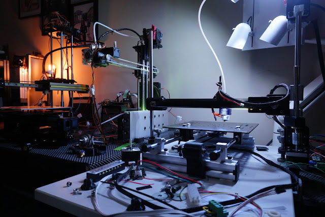
I'm tempted to leave the hotend at the back to keep things looking Sleek 

 So I either printed a Z motor mount or a Z Nut Lever....but I added a rod end to a Motor L plate to attach to the 12mm rod,
the new center was just out, so better to print a new lever rather than motor mount.
Edited 1 time(s). Last edit at 02/13/2018 04:30AM by MechaBits.


the new center was just out, so better to print a new lever rather than motor mount.
Edited 1 time(s). Last edit at 02/13/2018 04:30AM by MechaBits.
|
Re: For Anyone Who's Blindly Followed the I3 Design. February 13, 2018 04:41AM |
Registered: 8 years ago Posts: 1,671 |


|
Re: For Anyone Who's Blindly Followed the I3 Design. February 13, 2018 05:03AM |
Registered: 8 years ago Posts: 3,525 |
Nice looking machine, minimalistic, very atmospheric photography.
Do you think it will be stiff enough?
Simon Khoury
Co-founder of [www.precisionpiezo.co.uk] Accurate, repeatable, versatile Z-Probes
Published:Inventions
Do you think it will be stiff enough?
Simon Khoury
Co-founder of [www.precisionpiezo.co.uk] Accurate, repeatable, versatile Z-Probes
Published:Inventions
|
Re: For Anyone Who's Blindly Followed the I3 Design. February 13, 2018 08:22AM |
Registered: 8 years ago Posts: 1,671 |
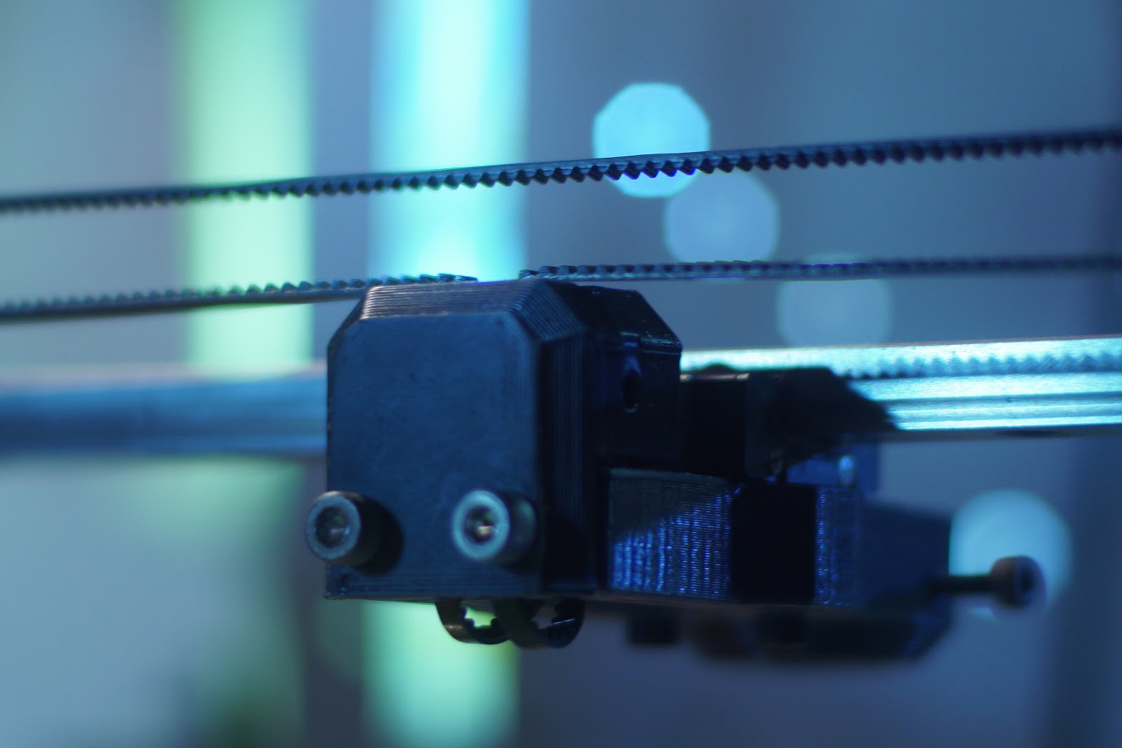
yeah it's stiff enough, given it a good tap and it's solid, if i grab the idle end of X and move it up & down I can do it but not much(perhaps a little flexing at the motor bracket, but doubt it will be a problem when printing.
We all know how 3D Printers Kinematics is something to think about .
I like to add a little 3D Printer Cinematics
Edited 3 time(s). Last edit at 02/13/2018 01:01PM by MechaBits.
We all know how 3D Printers Kinematics is something to think about .
I like to add a little 3D Printer Cinematics
Edited 3 time(s). Last edit at 02/13/2018 01:01PM by MechaBits.
|
Re: For Anyone Who's Blindly Followed the I3 Design. February 15, 2018 02:54PM |
Registered: 8 years ago Posts: 1,671 |
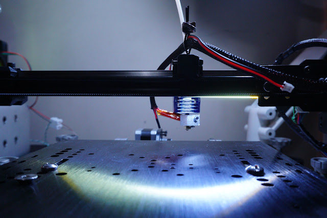
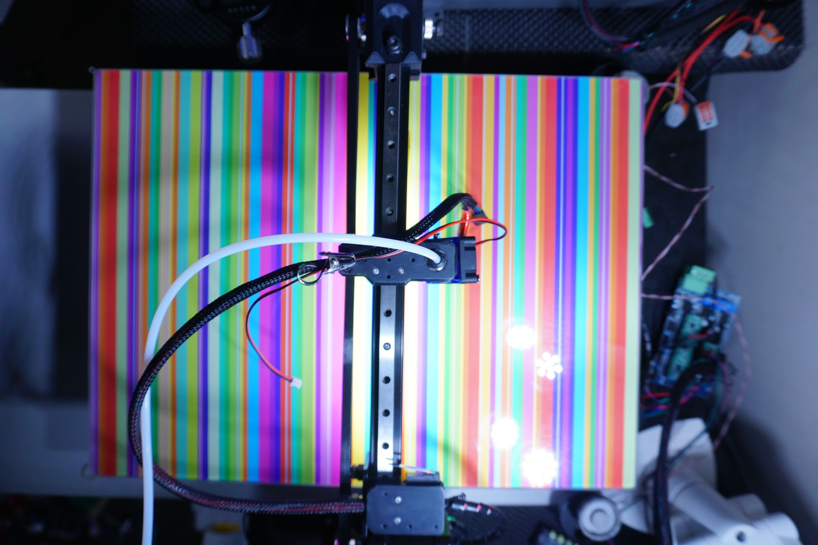
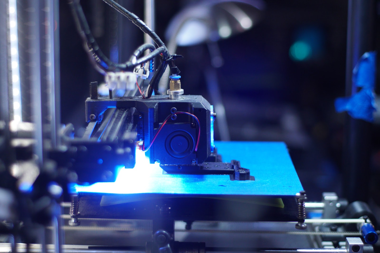
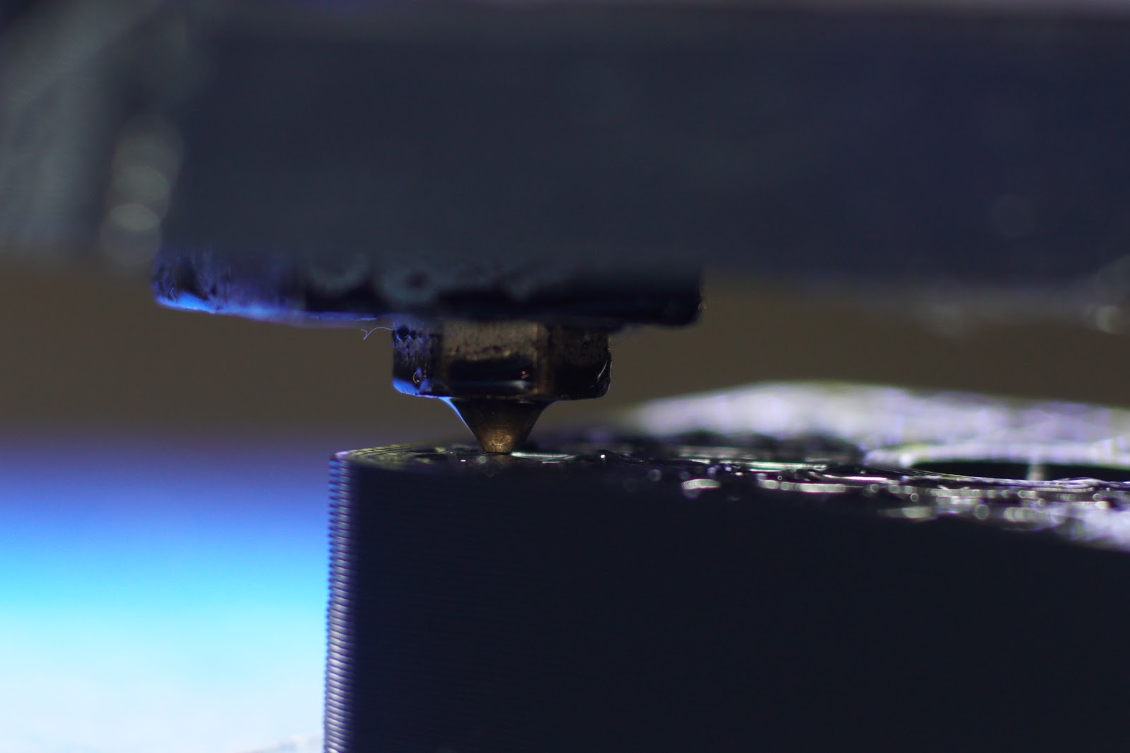
The LED's I fitted to the arm on other printer have many tiny points and no diffusion, it really shows up imperfections in prints, more the Z line registration, i'm not too bothered with the corner buldge(I was never happy with these white belts, and even the black belt I just got has the wire in it, I'd rather have the softer stuff than the shiney stuff), I find my LED a tad too bright for balanced pics, I think the new strip I have under this new printer even though its thinner seems to be more diffuse light throw, could be because i've no bed in there yet...
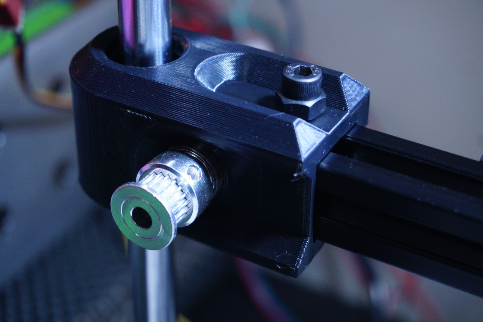
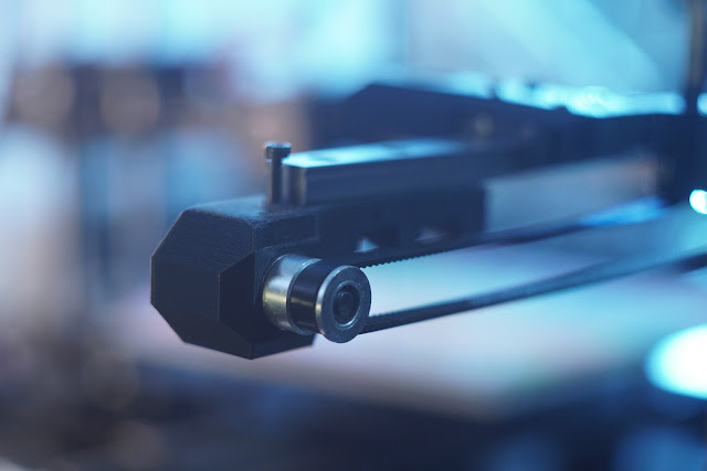
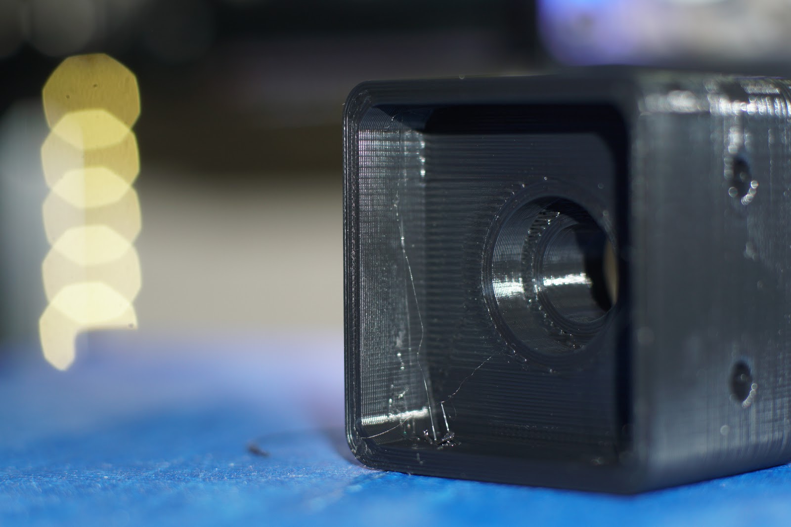
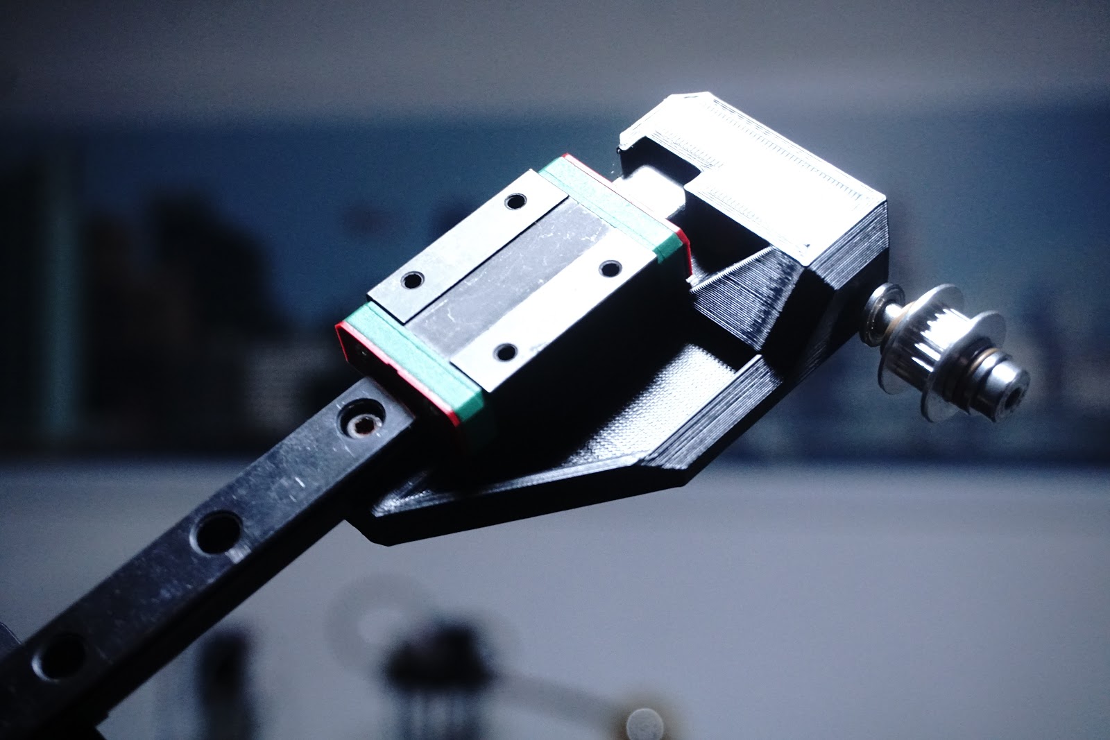
Changed the Z Motor Mount orientation to get head lower, dont think it looks as good this way round so I added a little plate I had to disguise it a little, also moved the linear rail to the top of the 2020, to make the hotend mount easier/smaller/tidier tiny 2mm screws are not the best for mounting the rail but look good on the cart...cant decide if it looks better with the streak of the silver rail or all slim & black like it was...does it make it look better built, look Ma! it has no wheels...
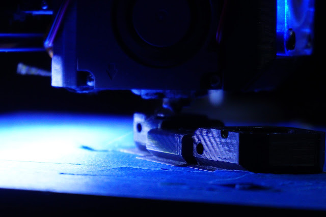
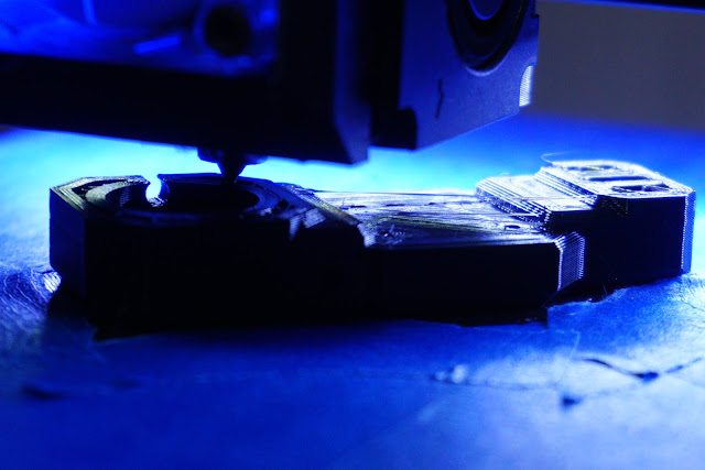
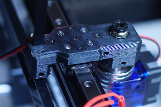
Changed the Z Motor Mount orientation to get head lower, dont think it looks as good this way round so I added a little plate I had to disguise it a little, also moved the linear rail to the top of the 2020, to make the hotend mount easier/smaller/tidier tiny 2mm screws are not the best for mounting the rail but look good on the cart...cant decide if it looks better with the streak of the silver rail or all slim & black like it was...does it make it look better built, look Ma! it has no wheels...


|
Re: For Anyone Who's Blindly Followed the I3 Design. February 15, 2018 03:40PM |
Admin Registered: 15 years ago Posts: 1,470 |
|
Re: For Anyone Who's Blindly Followed the I3 Design. February 16, 2018 07:52AM |
Registered: 8 years ago Posts: 120 |
|
Re: For Anyone Who's Blindly Followed the I3 Design. February 18, 2018 05:48AM |
Registered: 8 years ago Posts: 1,671 |
@New Perfection, glad you like it, it kinda feels like a new perfection
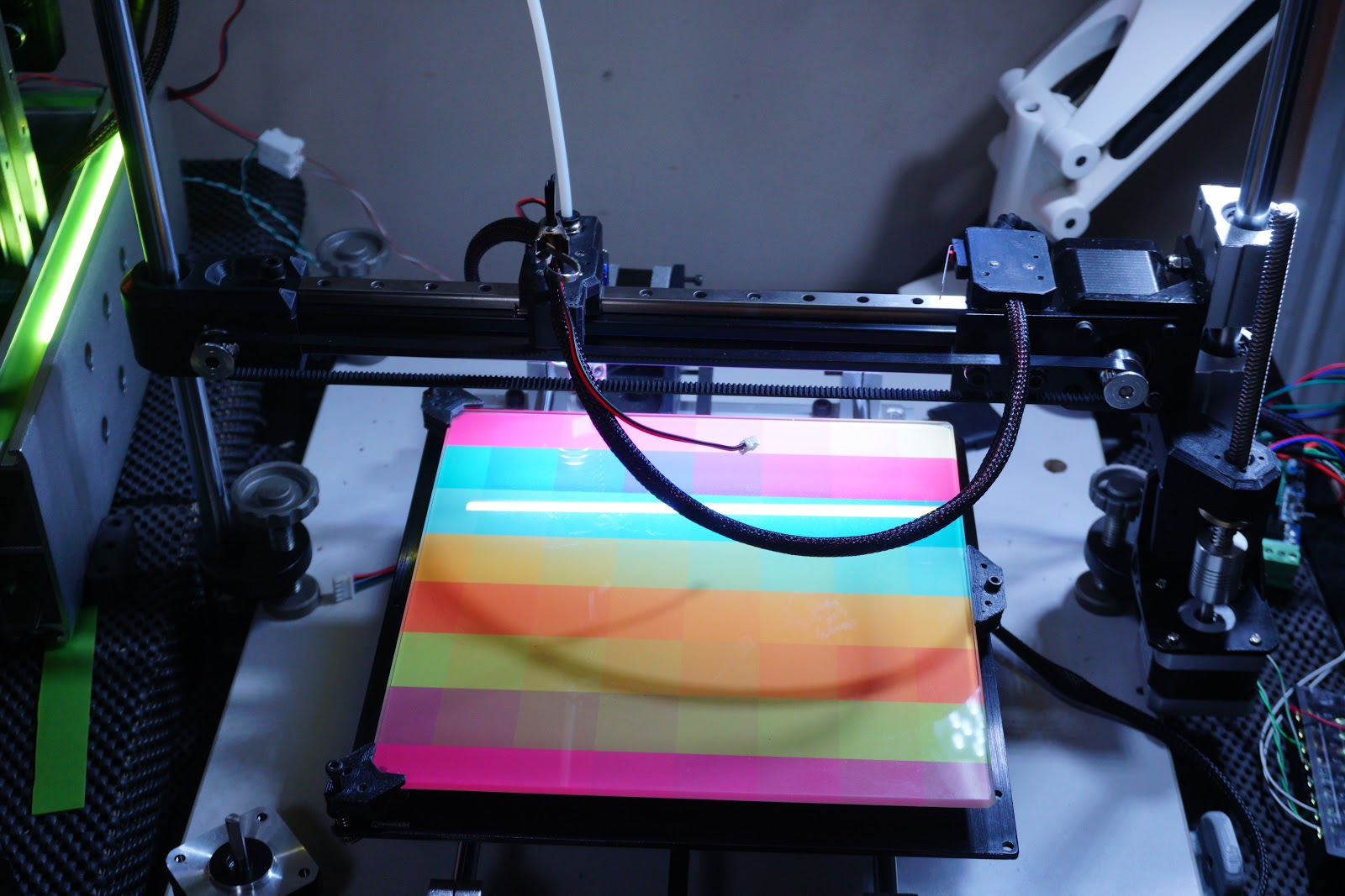
@Mathew It's very near complete, all wired up, a few new things came in post, cable sleeve & another openbuilds plate, now it ooze'z sex appeal, need another print surface, normally get the MK3b...even though i'm yet to wire any of them up, but I noticed a slightly larger heatbed but one that still has holes in same place as standard heatbed...so I can use this build plate with it...though for £20 I might as well treat myself to some cast plate 300x200 though perhaps not on 8mm rails, easy swap for 12mm rails though, I've a couple of little pieces to print still for it but just small cable guide & belt clip thing. I have some pics where I have a brace between rods at top but they restrict print height, and it looks much cleaner without, i mounted the extruder at top of rod same method as Z motor.
As much as I like it as it is , i'm also tempted to strap it to one of the last available sides of the borg box assimilator.
Edited 4 time(s). Last edit at 02/19/2018 05:27AM by MechaBits.


@Mathew It's very near complete, all wired up, a few new things came in post, cable sleeve & another openbuilds plate, now it ooze'z sex appeal
, need another print surface, normally get the MK3b...even though i'm yet to wire any of them up, but I noticed a slightly larger heatbed but one that still has holes in same place as standard heatbed...so I can use this build plate with it...though for £20 I might as well treat myself to some cast plate 300x200 though perhaps not on 8mm rails, easy swap for 12mm rails though, I've a couple of little pieces to print still for it but just small cable guide & belt clip thing. I have some pics where I have a brace between rods at top but they restrict print height, and it looks much cleaner without, i mounted the extruder at top of rod same method as Z motor.As much as I like it as it is , i'm also tempted to strap it to one of the last available sides of the borg box assimilator.
Edited 4 time(s). Last edit at 02/19/2018 05:27AM by MechaBits.
|
Re: For Anyone Who's Blindly Followed the I3 Design. February 19, 2018 05:26AM |
Registered: 8 years ago Posts: 1,671 |


Not much more I can do without ordering a few things, 300mm lead, Heatbed, though might try just mounting the glass tile, design another part cooler, holding back on printing box for ramps, I need a few and they eat plastic, and i'd much rather have a better simple alu project case, unless I can think of something cool that needs to be printed.
Edited 1 time(s). Last edit at 02/20/2018 03:55AM by MechaBits.
|
Re: For Anyone Who's Blindly Followed the I3 Design. February 19, 2018 08:04AM |
Registered: 8 years ago Posts: 5,232 |
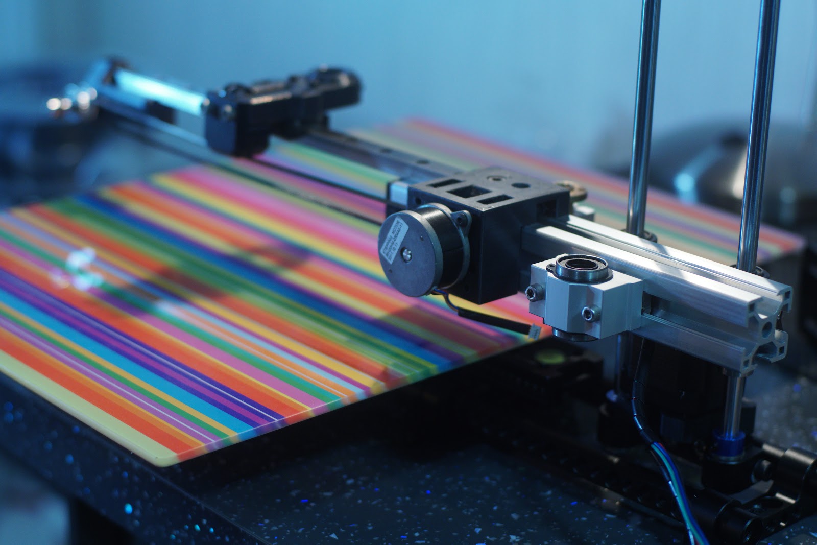
What is the purpose of the vertical smooth rod on the left of the printer?
It only keeps the X-carrier arm from rotating? Bot OTOH,there is a risk for racking because it is passive ( not driven )
Is there a cleaner solution to fulfil the same purpose, like adding a second rod to the right?
It only keeps the X-carrier arm from rotating? Bot OTOH,there is a risk for racking because it is passive ( not driven )
Is there a cleaner solution to fulfil the same purpose, like adding a second rod to the right?
|
Re: For Anyone Who's Blindly Followed the I3 Design. February 19, 2018 11:36AM |
Registered: 6 years ago Posts: 1,007 |
Why blindly follow ?
The Prusa is just an evolution of this set up. It doesn't require such a sturdy base, beefy smooth rods and even beefier brackets to secure them to the base. Easier to make the rods // and stay //. Two more bars from rod tops to the base and it is rock solid.
The main issue of the Prusa is the moving Y table (and the two Z motors for the original and clones)
"A comical prototype doesn't mean a dumb idea is possible" (Thunderf00t)
|
Re: For Anyone Who's Blindly Followed the I3 Design. February 19, 2018 11:56AM |
Registered: 8 years ago Posts: 1,671 |
@Olampe, your right on one thing about the bar on the right, it stops any unwanted movement, it is passive and doesnt bind, most of my other printers have rods to the right, ie 2 rods near each other, i've been told a few of them would rack too. The other new arm I have will have 2 rods closer to each other, with the rail coming out from them.
@MKSA The Prusa with all the threaded rods is the one I was singling out, I dont deny it makes a strong frame, with lots of pieces( & looks really bad especially when the metal dulls, nasty), Sometimes the Evolution is less parts more refined, not more parts & complexity. I have a brace for the top, but dont think it needs it, the mounts the rods are in have 2 grub screws to lock the rods, If I made my own base, I would try to loose the mounts I have, and just have holes in a thick worksurface, and if that wasnt good enough, i'd introduce a few rod ends top & in recessed worktop bottom, or just put base on some feet so I didnt have to make a recesses.
Many other printers gain rigidity from the desk they are place on, why not have 2 holes in your desk...then I dont need the piece of wood.
Also the clamps I have 2 with Rods & 2 without, the ones without are used as feet, but I could use them for some buttressing, but it would be more vertical rods, and i'd have to make more of a box, more work to do diagonals.
Edited 2 time(s). Last edit at 02/19/2018 03:06PM by MechaBits.
|
Re: For Anyone Who's Blindly Followed the I3 Design. February 19, 2018 04:22PM |
Registered: 6 years ago Posts: 1,007 |
Quote
MechaBits
@Olampe, your right on one thing about the bar on the right, it stops any unwanted movement, it is passive and doesnt bind, most of my other printers have rods to the right, ie 2 rods near each other, i've been told a few of them would rack too. The other new arm I have will have 2 rods closer to each other, with the rail coming out from them.
@MKSA The Prusa with all the threaded rods is the one I was singling out, I dont deny it makes a strong frame, with lots of pieces( & looks really bad especially when the metal dulls, nasty), Sometimes the Evolution is less parts more refined, not more parts & complexity. I have a brace for the top, but dont think it needs it, the mounts the rods are in have 2 grub screws to lock the rods, If I made my own base, I would try to loose the mounts I have, and just have holes in a thick worksurface, and if that wasnt good enough, i'd introduce a few rod ends top & in recessed worktop bottom, or just put base on some feet so I didnt have to make a recesses.
Many other printers gain rigidity from the desk they are place on, why not have 2 holes in your desk...then I dont need the piece of wood.
Also the clamps I have 2 with Rods & 2 without, the ones without are used as feet, but I could use them for some buttressing, but it would be more vertical rods, and i'd have to make more of a box, more work to do diagonals.
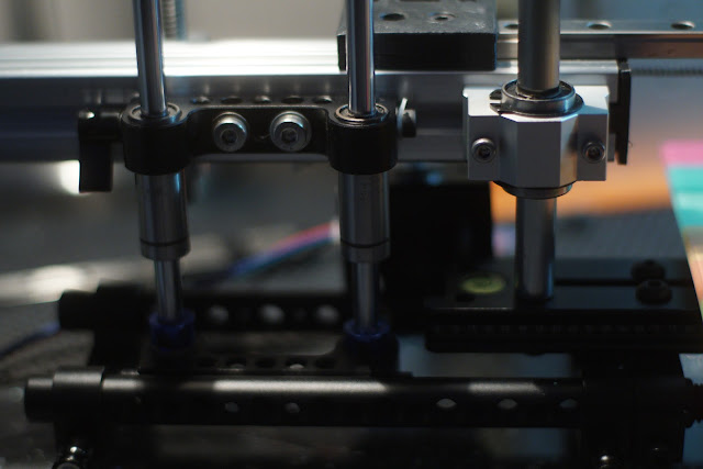
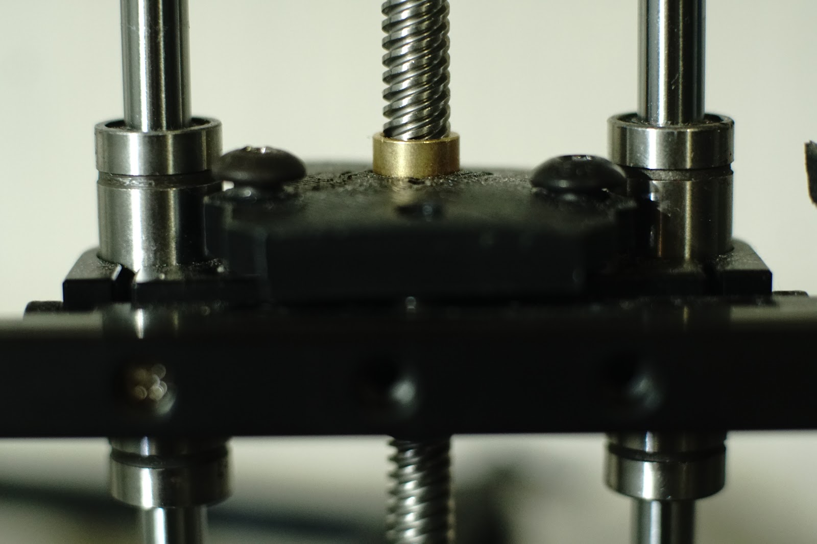
Curious to see how // the two vertical rods are !
From the picture the lead screw doesn't seem // to them either, I hope it is just the picture. Anyway, as long as everything is somewhat flexible it won't bind.
Edited 1 time(s). Last edit at 02/19/2018 04:23PM by MKSA.
"A comical prototype doesn't mean a dumb idea is possible" (Thunderf00t)
|
Re: For Anyone Who's Blindly Followed the I3 Design. February 19, 2018 07:18PM |
Registered: 8 years ago Posts: 1,671 |
you have a good eye, the thing for the leadscrew was measured in place(more than twice), i'd say I got the position of the hole out by .5mm or 1mm but a little tilt on a leadscrew never hurt anyone, as for the rods they are both mounted to the board in the same way, they could be out, but I cant see it or feel it, and as I can move the rod mount easy if I want to make the printer cantelevered I bring the rod to motor side, and make some spar's or something, but it is only there to stop rotation, the main rod(or lead) is taking all the weight.
|
Re: For Anyone Who's Blindly Followed the I3 Design. February 20, 2018 03:52AM |
Registered: 8 years ago Posts: 1,671 |


Not Quite as Ingenious as LoboCNC's Inverted Machine, but I'm happy with what was just a box of bits cluttering up the box of bits.
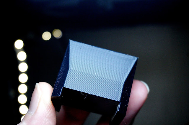
Printed the glass holder, but I made them too small 10g's, needs more support below and a little more at top,
and I need more screws rapidly running out of all sizes.
|
Re: For Anyone Who's Blindly Followed the I3 Design. February 24, 2018 03:27AM |
Registered: 8 years ago Posts: 1,671 |


|
Re: For Anyone Who's Blindly Followed the I3 Design. March 05, 2018 05:06PM |
Registered: 8 years ago Posts: 1,671 |


Another Machine takes shape from a left over Z & X, this X was due for a 12mm rod upgrade, but I've decided to try with 2x 8mm and 1x 12mm, plus leadscrew, was thinking of belt driving it as it seemed a better way to place things, but may just go direct(needs a black motor, the new motor plates will arrive tomorrow so a few more changes will be made, not quite decided on belt route, but it has to clear lead and thaat motor will once again go in the box of props...
I have a longer black linear rail I wouldnt mind using as it would be well supported by the 3030, and look a little sexier,
I would like a way to sling the plate around with a rubber wheel/bearing system, keeping the most level point in the central line with head(though obviously you dont want any play).
Edited 1 time(s). Last edit at 03/06/2018 06:57AM by MechaBits.
|
Re: For Anyone Who's Blindly Followed the I3 Design. March 06, 2018 06:48AM |
Registered: 8 years ago Posts: 1,671 |
Maybe this is the arrangement? even with limited parts there is still a number of ways to put it together.
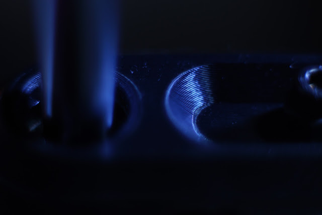
In this setup I have this left over 12mm bar from a telescope, but the chrome finish is bad, I dont want to use it for any length of time.
But it has a unique feature I wish all Rods came with, a screw hole in the end(or thread on end would be good)
the screw hole lines up with a hole in the base so I dont need a rod end there, I wish all rods had one, things would go together even easier, with less parts. Postman comes in one hour....clock watching slows time.
Edited 5 time(s). Last edit at 03/07/2018 05:45PM by MechaBits.
|
Re: For Anyone Who's Blindly Followed the I3 Design. March 10, 2018 06:19PM |
Registered: 8 years ago Posts: 1,671 |
Postman was a few days late...


so I had to make some parts before he came to keep occupied, I did the carriage(will replace the screws at some point) & idler, nice 8mm shaft/bolt but shaft only 30mm so need to order another about 40mm so I can mount the pulley flipped, so grub screw is near threaded end but still on shaft,, I need it flipped to align with the motor pulley, closer to profile so it clears the leadscrew. the Z parts I wanted to leave till the plates arrived, I need a smaller motor, and might get the one i spotted the other week which has shaft out the back, like this dual one i'm using, allowing for this mount method. I'll probably be using the 3030 profile bed, as it clamps right on, one piece of profile left so might make another bed with that, but still considering other designs for the fun of it.
Edited 3 time(s). Last edit at 03/12/2018 10:48AM by MechaBits.
|
Re: For Anyone Who's Blindly Followed the I3 Design. March 11, 2018 03:42AM |
Registered: 6 years ago Posts: 1,007 |
|
Re: For Anyone Who's Blindly Followed the I3 Design. March 11, 2018 08:24AM |
Registered: 8 years ago Posts: 1,671 |
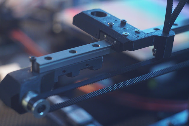
I wouldnt know...It's as tight as I can get it, I assume your not impressed by the 2 screws and unsupported rail, the motor mount I removed was performing 2 jobs one to anchor the rail, a replacement part will be printed to keep things locked down, but its holding up without... easy enough to replace the 3030 for a longer piece, maybe i'll get a black one at some point, but not so sure about the V-Slot stuff, looks a little thin, and the edge not good for seating rails.
Edited 1 time(s). Last edit at 03/11/2018 11:57AM by MechaBits.
Edited 1 time(s). Last edit at 03/11/2018 11:57AM by MechaBits.
|
Re: For Anyone Who's Blindly Followed the I3 Design. March 27, 2018 05:24PM |
Registered: 8 years ago Posts: 1,671 |
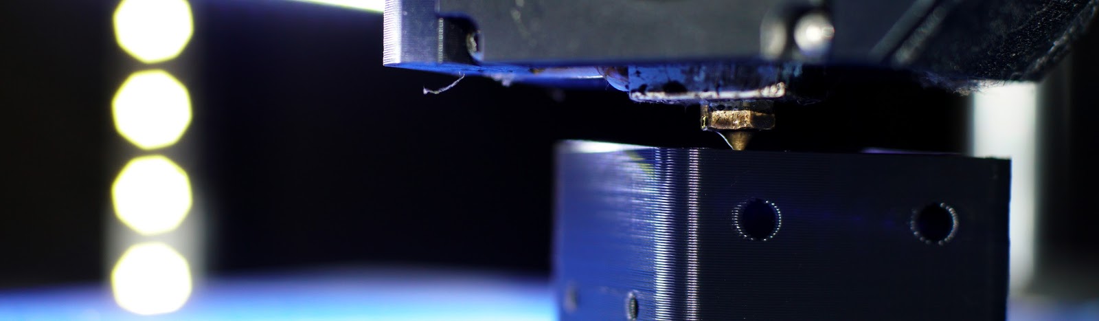


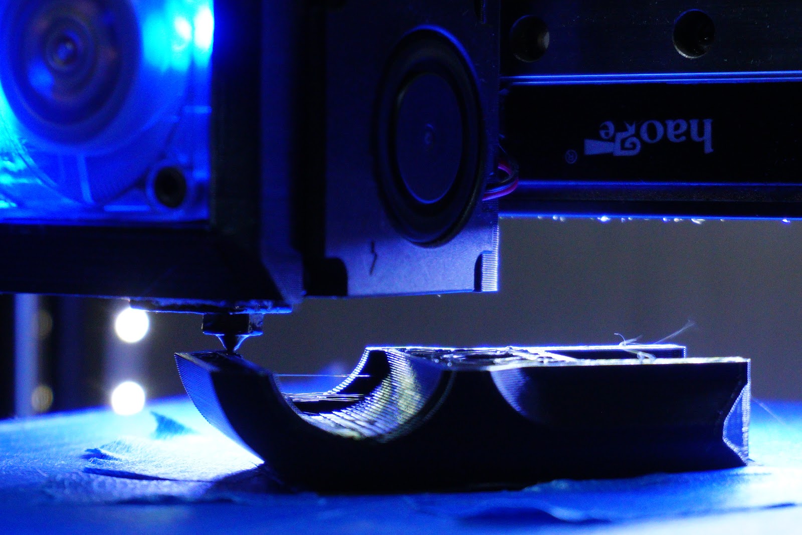
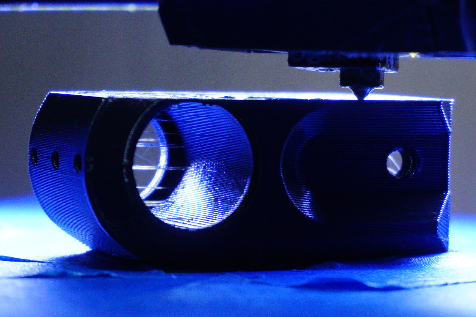
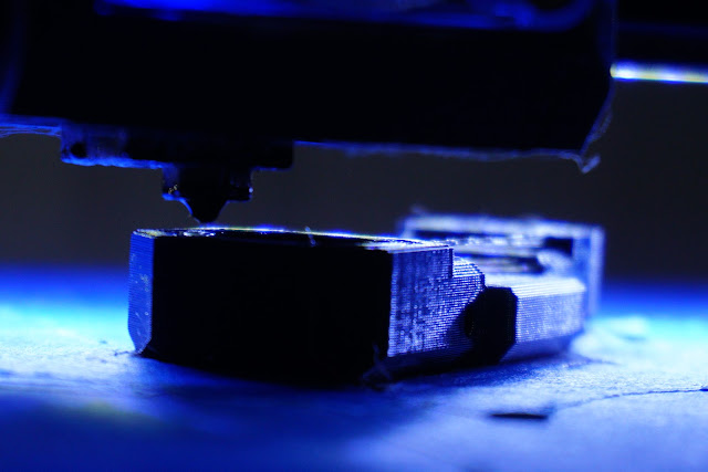
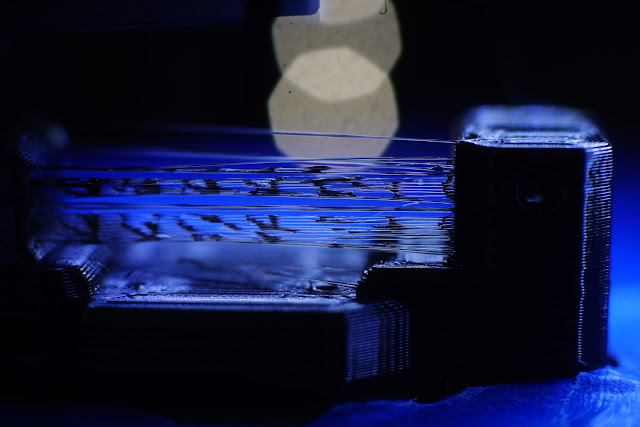
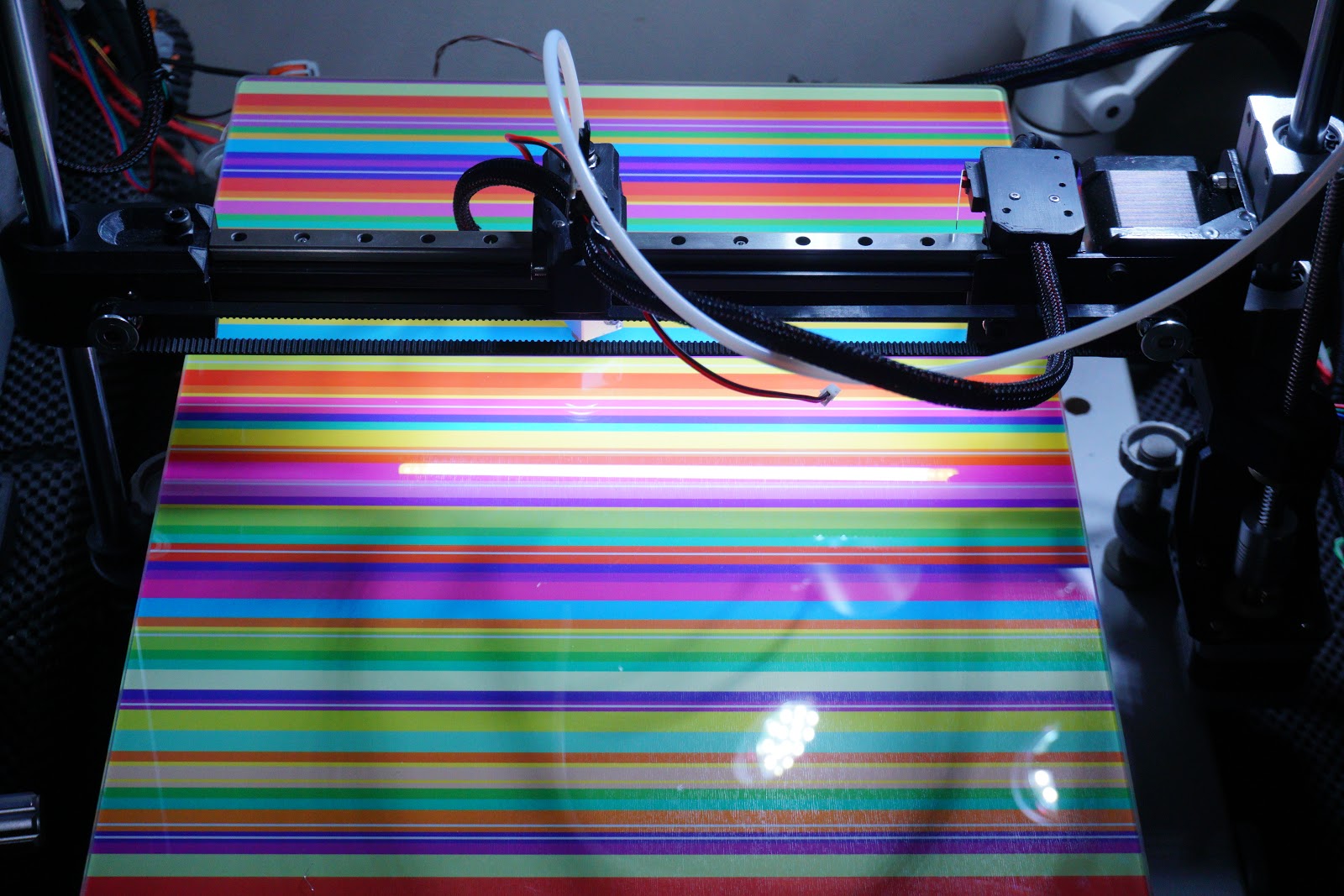
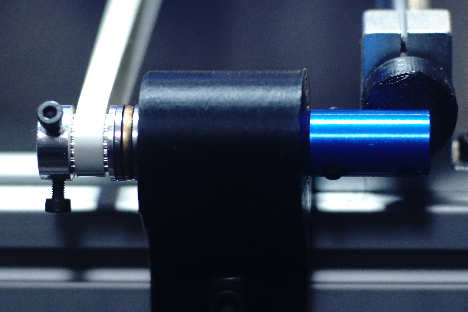
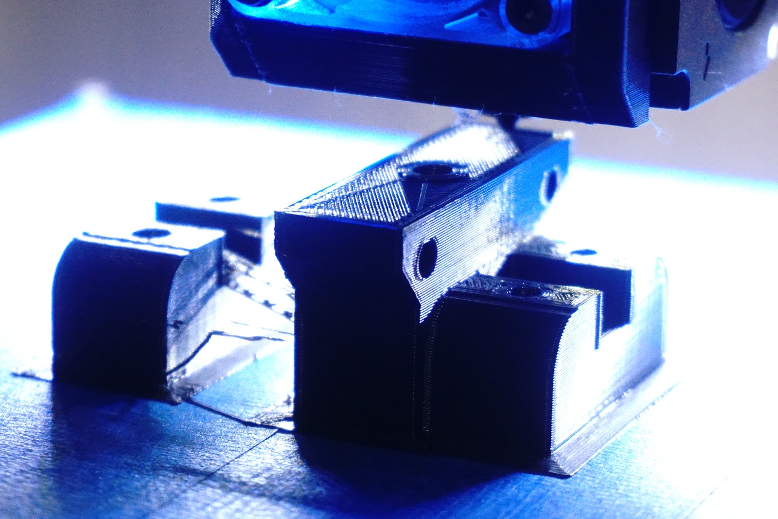
Turned on the light's and caught these two Cantilever's getting up to some FFFornication, Buttressing, and Synchronized Screwing
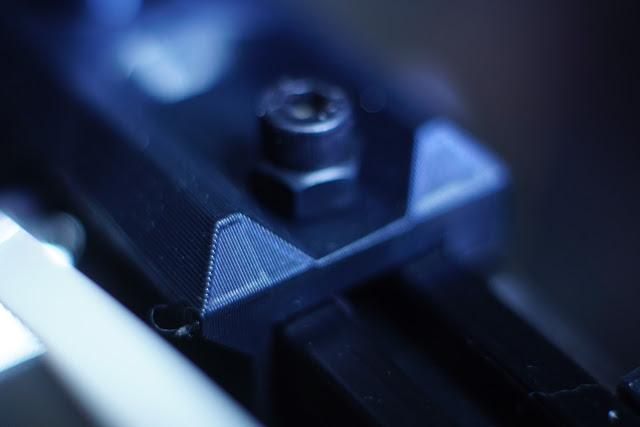
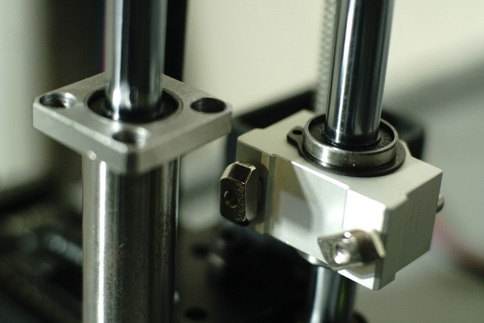
New Parts arrive Forks in the Road appear ahead. I had this dual 8mm rod Z on the go, then some more 12mm rods arrived and another Z arrangement takes shape, mulling over a couple of ways to do it, all depending on how I want to pair it up with the 8mm Z, or another mirrored 12mm Z setup. Ideally I prefer not to have the second Z as I can't be bothered with 2 Z motors, But it's also very tempting to have at least one printer that does have 2xZ's....with the ability to split into 2 Cantilever Printers when you want. The 12mm rods(best yet with nice chamfers) could be held in at least 3 different ways...and as I only have 2 for this printer at the moment,now I need another four rods
to try out the ideas spawned, the ideal would be one each side rather than the 8mm Z, so it isnt what I wanted to do with the rods but it's one of the possible futures that have opened up. Will probably use the long 12mm Flange Bearing, instead of the shorter one, and instead of using both...though I still feel I should design the part that uses both, just incase... though thats probably a dead end, better to keep things symmetrical. Nice dark blue couplers arrived 4x one day 3x the next, must have ordered twice?Edited 6 time(s). Last edit at 03/29/2018 01:11AM by MechaBits.
|
Re: For Anyone Who's Blindly Followed the I3 Design. March 30, 2018 11:52PM |
Registered: 8 years ago Posts: 1,671 |

This going to be a little tricky(maybe not as much as CoreXY) but I really dont want big blocky plastic parts,
I need to run the belt for the bed but there's a few obstacles to overcome.
2 idlers for the ends, and 2 more above motor, the ones above motor will have to be bearings on 5mm shaft but I can only seat the bolts 5-10mm, unless i do a design that shifts the idlers out beyond the motor mount to left or right, end idlers could be either.
Also wondering if I should flip the motor and have belt path more hidden underneath, though it wouldnt be central and also need to go above carriage, ideally a custom metal motor mount.
Edited 1 time(s). Last edit at 03/31/2018 12:00AM by MechaBits.
|
Re: For Anyone Who's Blindly Followed the I3 Design. April 02, 2018 02:57AM |
Registered: 8 years ago Posts: 1,671 |
I've replaced the 8mm bolt for 8mm shaft on printer as I knew it wasnt ideal for idler to be sitting on a thread, and I changed over to a new roll in a new position, and got stuck in to some 2 new parts after a week or more of no printing(end of roll design constraints),
I probably could have squeezed these 2 parts out of the last roll, but filament snapped so was a good time to switch over, I was raring to go wondering if i'd see an improvement, I also decided to turn off Z hop and see what happens as I knew i'd probably improve things and remove some of the NanoMrWhippieTurds that can develop. I think i'll be doing more prints without Z-Hop, but I could probably tune it a little more to get the best out of this £5 feeder. While I finalize design of end idlers i'll decide if I need another version of this motor mount thing, a little higher with more pulley room, ideally for just bearings but dont have any 5mm ones left.


Edited 1 time(s). Last edit at 04/04/2018 02:43AM by MechaBits.
|
Re: For Anyone Who's Blindly Followed the I3 Design. April 04, 2018 09:52AM |
Registered: 8 years ago Posts: 1,671 |


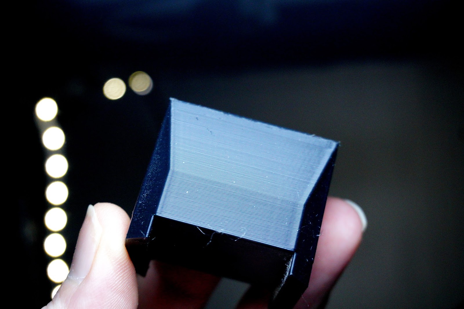
What a pain to have to wait for more bearings before I can test this thing out, unless I can find some redundant ones lodged in other parts. Re-did the motor thing so as to give the other 2 parts even more time to cool, but messed up a little, decided to set layers to 0.2 and perim from 4-5....but really coming from .28 I really should have added more top & bottom too and maybe even more perim. Realized on first layer but it seemed to be doing well, I thought lets see how the part holds up...as I might have a tendency to over engineer, and could get away with less material. Slight warp on one but aside from that it fits nice. Will reduce images when I get around to it.
Edited 1 time(s). Last edit at 04/05/2018 10:11AM by MechaBits.
|
Re: For Anyone Who's Blindly Followed the I3 Design. April 10, 2018 10:33AM |
Registered: 8 years ago Posts: 1,671 |


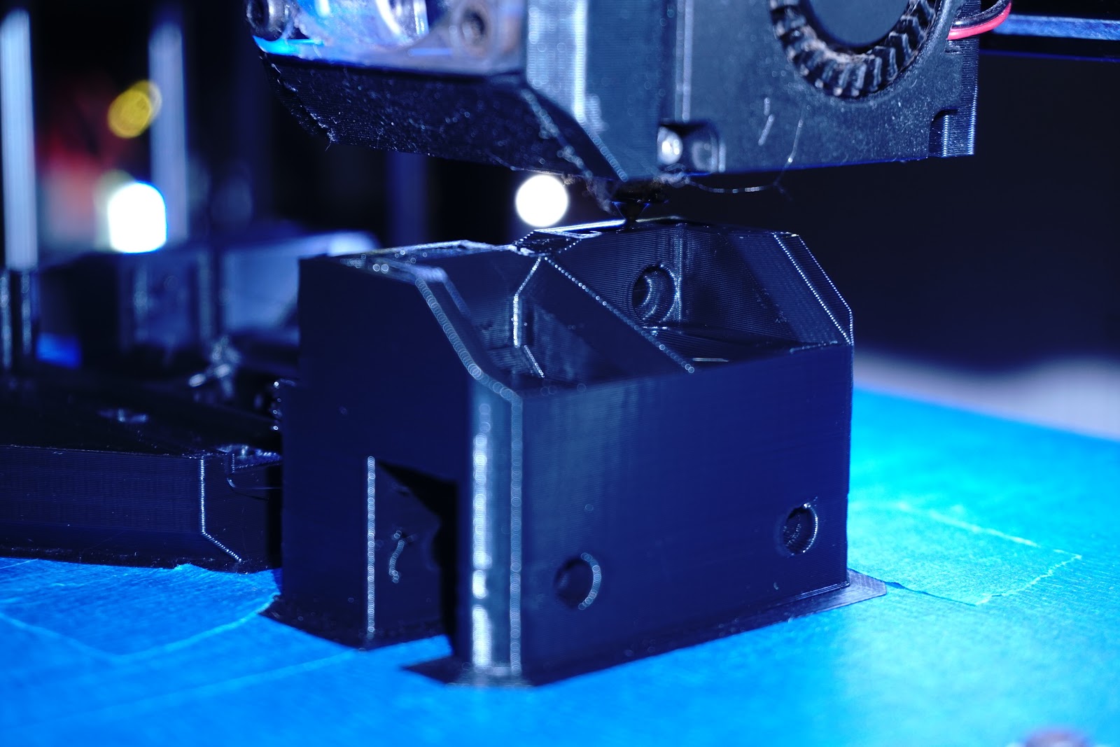
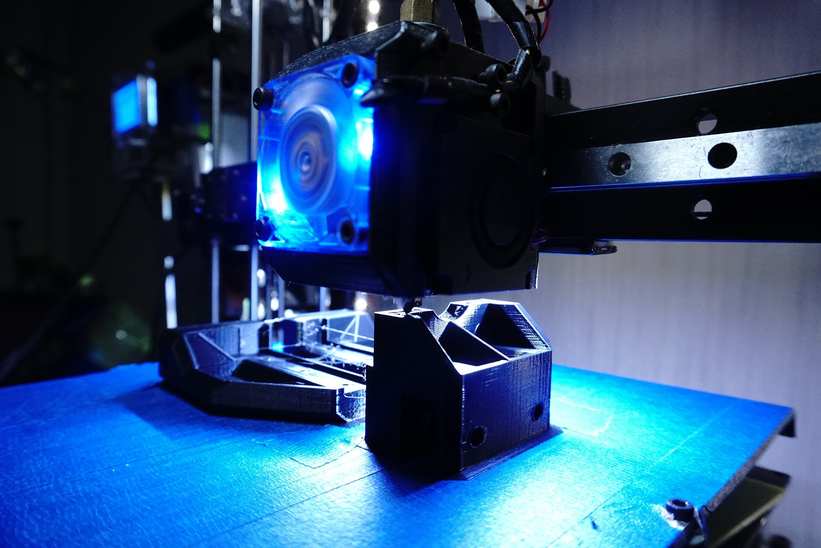
Funny how one thing leads to another, some new printed parts to make possibly the last iteration of a Mechabits 3D Printer, as now it really is time to focus on a little mill/lathe. I printed the carriage first and could have made it the length of the bearings but decided on 20mm instead and I'm very happy with its strength & stiffness...then I decided to finish it off with 2 other custom parts for the motor mount & idler, so I didnt have to use the motor plates, or other parts designed for other machines, but now these parts are done I'm drawn to replacing some more metal parts with some other custom parts, so one part for base & one for the top, 6 parts down to 2, threaded rods would reduce things even further. Also now I have to make something to hold linear rail in place, shoud I go with one or 2? hmmm??? Would be nice to have a symmetrical 2 rail arm but I think i'll go with one for now. As I was piecing this axis together my thoughts turn to it's use as a mini lathe instead of a Z, where a fatter carriage would be even better, but for now i'm happy enough perhaps a second version of the carriage incorporating a motor mount rather than adding it on a another piece, but still figuring out where i need the motor, as the idler is now sorted, I need to line things up, print 2 pieces to hold the rail in-place & and maybe the idler too...
Edited 4 time(s). Last edit at 04/11/2018 03:17PM by MechaBits.
|
Re: For Anyone Who's Blindly Followed the I3 Design. April 12, 2018 07:50AM |
Registered: 8 years ago Posts: 1,671 |


Last 2 parts needed are the motor mount & hotend carriage, oh no! not another carriage to design, will probably just mod one I did for these small 9mm rails, have to try to keep it small & lo profile if poss', and doing all this knowing that as soon as another part I've ordered turns up, i'll be redesigning an alternative arm for this machine with another of these 9mm rails....might as well try to use them, but I wont bother with them in the future the 2mm screws are too much of a pain.
Edited 2 time(s). Last edit at 04/13/2018 06:54AM by MechaBits.
|
Re: For Anyone Who's Blindly Followed the I3 Design. April 13, 2018 12:40PM |
Registered: 8 years ago Posts: 1,671 |


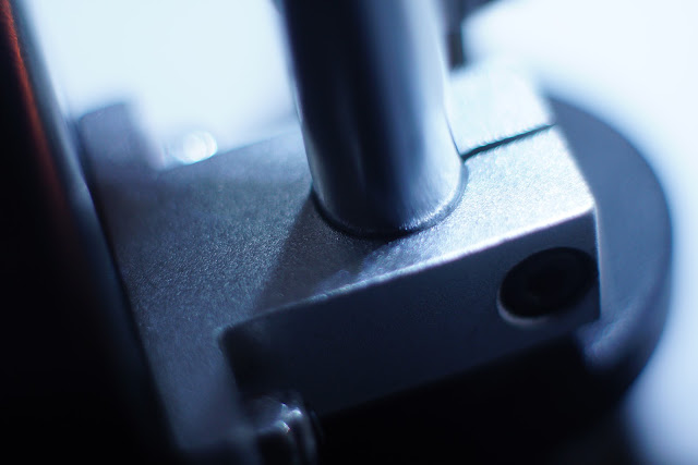
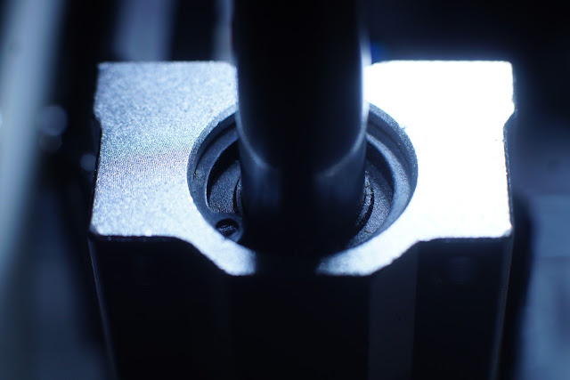
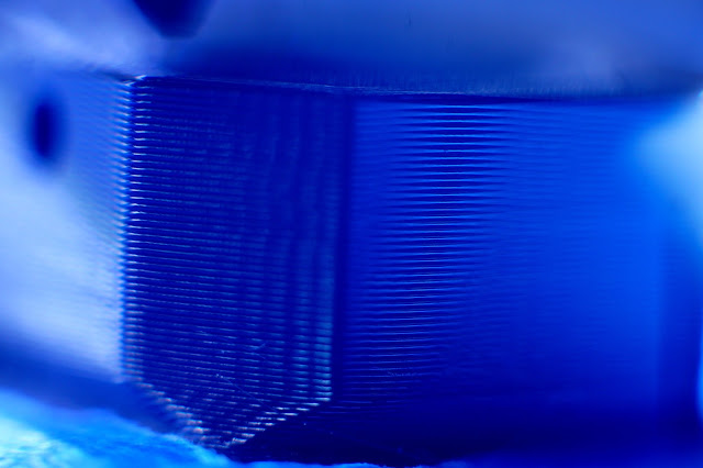
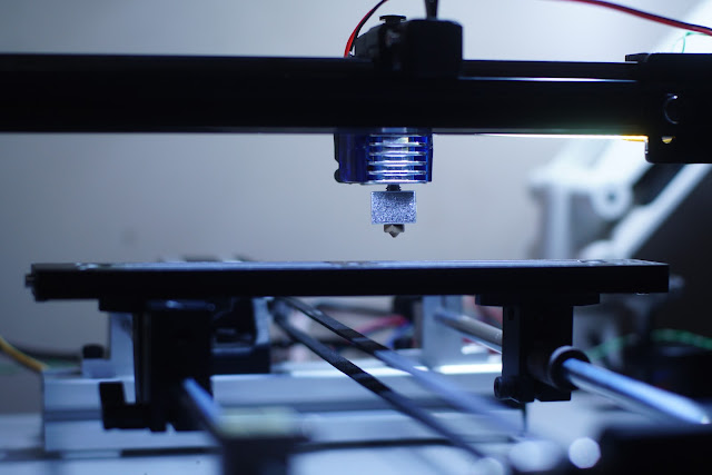
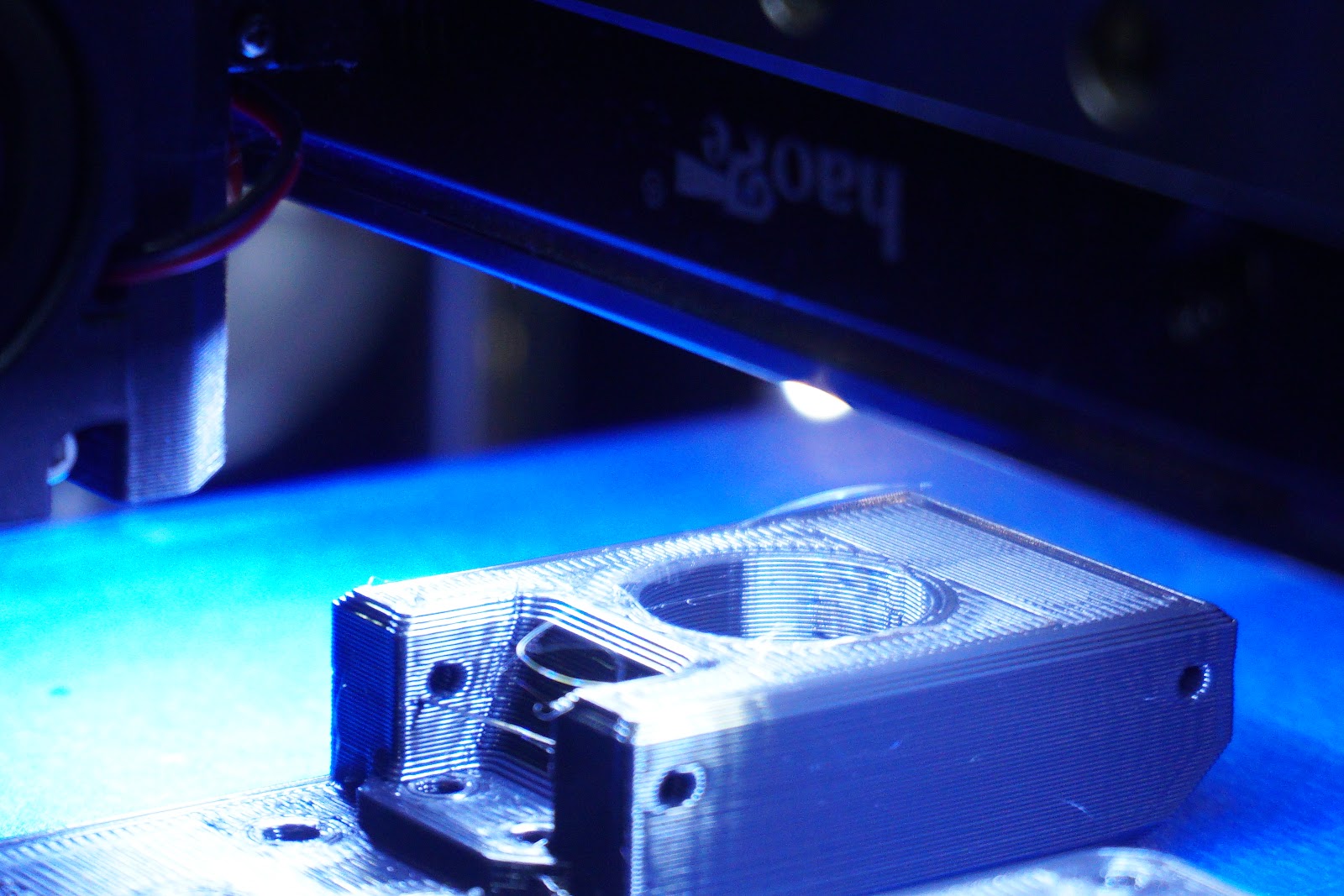
now if only I had a 1/4 UNC - 5mm Shaft, I could have saved some time on printed parts, and it would retain its desired look.
Wonder what the layer heights on the side of the nema are, not a bad match.
even though I plan on creating another final arm for this with plate rather than rods, the thought of changing one on the black rods
for another 12mm rod could be better layed out arrangement, ditching the linear rail and trying to fit hot end between rails...
Edited 2 time(s). Last edit at 04/15/2018 07:01AM by MechaBits.

Sorry, only registered users may post in this forum.