Design Review! Looking for comments / critiques and ideas for my new printer build.
Posted by Ed3D
|
Design Review! Looking for comments / critiques and ideas for my new printer build. November 24, 2018 03:11PM |
Registered: 5 years ago Posts: 61 |
I think this is going to be quite a lengthy post so please bear with it! I’ve been working on this design for a printer for a couple of months now and I think I’m almost finished (famous last words) and ready to start ordering parts and building! What I’m looking for some thoughts on the designs and any ideas you can think of to improve the design before I build prototype one!
The basic spec for the machine is to be a high quality (but reasonable cost) PLA, single material printer, with a 200 x 200 mm print area (220 x 220 mm build plate). Secondary targets are that it is reliable and easy to use (auto-level), low noise and reasonably compact. I have opted to use linear rails across all axis for the rigidity and smooth motion. I plan for this to be open source once I have created the first prototype.
Here is the general design: (Image)
So here is the spec, specific design and thoughts.
Print head: (Image) – Still a work in progress, need to add the BLTouch and more effective exhaust vents
X Axis: (Image)
Y Axis: (Image - Upside-down)
E Axis: (Image)
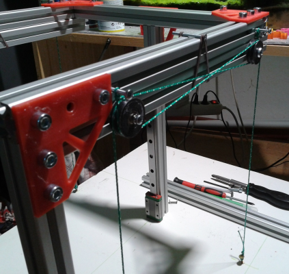
Z Axis: (Image)
Bed: (Image)
Frame: (Image)
Electronics:
I’m really interested to hear what you think of the design and any comments / suggestions you have. I also don’t have a good name for this thing yet (thus PRINTER). If you have any name suggestions, I’d love to hear them!
(If youre interested you can see how the design has developed here)
Edited 3 time(s). Last edit at 11/24/2018 03:27PM by Ed3D.
The basic spec for the machine is to be a high quality (but reasonable cost) PLA, single material printer, with a 200 x 200 mm print area (220 x 220 mm build plate). Secondary targets are that it is reliable and easy to use (auto-level), low noise and reasonably compact. I have opted to use linear rails across all axis for the rigidity and smooth motion. I plan for this to be open source once I have created the first prototype.
Here is the general design: (Image)
- Core XY – lightweight printhead for quick printing (still not added the AB Drive mounts)
- 3030 frame – very rigid
- Enclosed electronics
So here is the spec, specific design and thoughts.
Print head: (Image) – Still a work in progress, need to add the BLTouch and more effective exhaust vents
- E3D V6 with Bowden, with titanium heat-break, silicone sock. – Titanium gives a sharper definition between hot and cold and strengthens the hotend.
- BMG extruder – dual driving gears for ultimate grip and gear reduction for more precise filament movement.
- Two 4010 blowers for part cooling
- One 3010 cooling fan for the V6.
- BLTouch – mechanical auto levelling so any print surface can be used and minimal inaccuracy.
X Axis: (Image)
- MGN9 rail running across 5mm plywood beam – Hopefully very rigid. My main concern with the current design is twisting in this axis - any thoughts?
Y Axis: (Image - Upside-down)
- Dual MGN 12 rails bolted to frame
E Axis: (Image)
- Tensioner built into the head mount allows for individual tensioning so you can square up the X perfectly.
Z Axis: (Image)
- 4 MGN12 linear rails mounted to the frame
- 3 lead screws in a triangle – fully defines the bed plane
- Belted Z screws – all three screws belted together to prevent misalignment of the Z platform. - A touch concerned about tooth engagement on some of the pulleys but its apparently within spec.
- Tensioner to be designed.
- Single motor drive – no worry about motors running out of sync
- Antibacklash Nuts (mounted side down) to seat the bed perfectly at all times.
Bed: (Image)
- Mk3a PCB heated bed – Reliable non-mains heating.
- ULTRABASE glass tile clipped on top – Gives great adhesion and good flatness - (I may opt to use a silicone heater bonded directly to the Glass tile)
- 2020 frame for mounting the bed
Frame: (Image)
- 3030 Frame – very rigid
- Corner plates – keeps frame square and rigid.
- Blind joints – bolting directly into the end of each extrusion to give good metal on metal connection.
- Printed Feet (PLA to start, TPU one day) – A little vibration insulation and less scratchy on the table than bare extrusion!
Electronics:
- 24V System
- Duet wifi controller with TMC 2660 drivers (I know you're here somewhere DC42 - I cant get enough of the duet, its great)
- Sonoff Smart switch for remote mains control and auto power off after longer prints.
- RGB skirt and part lighting to indicate printer mode (Red = Heating, Blue = Printing / idle etc)
I’m really interested to hear what you think of the design and any comments / suggestions you have. I also don’t have a good name for this thing yet (thus PRINTER). If you have any name suggestions, I’d love to hear them!
(If youre interested you can see how the design has developed here)
Edited 3 time(s). Last edit at 11/24/2018 03:27PM by Ed3D.
|
Re: Design Review! Looking for comments / critiques and ideas for my new printer build. November 24, 2018 06:35PM |
Registered: 10 years ago Posts: 14,672 |
Good luck with your build! I have a couple of comments:
- 4 linear rails will be difficult to align. Most CoreXY designs use just 2.
- Bonding a silicone heater directly to the glass bed will give you uneven heat distribution, and you would need to use borosilicate glass, and you will lose the advantage of being able to swap glass plates. Better to bond the silicone heater to the bottom of a flat plate (preferably cast aluminium tool plate) and clip the glass on top.
Large delta printer [miscsolutions.wordpress.com], E3D tool changer, Robotdigg SCARA printer, Crane Quad and Ormerod
Disclosure: I design Duet electronics and work on RepRapFirmware, [duet3d.com].
|
Re: Design Review! Looking for comments / critiques and ideas for my new printer build. November 24, 2018 07:19PM |
Registered: 5 years ago Posts: 61 |
Thanks a lot!
In terms of the points you raise:
- I absolutely agree that 4 rails is going to be a challenge to prevent binding and I spent quite a long time going back and forth on it. In one iteration I had 3 rails aligned with the leadscrews. I settled on 4 because I think it will give the absolute best stability but have put a couple of things in place to help align them. First the bed extrusion to rail carriage mount is bolted into place and actually has +/- about 5 mm of travel each so the rails can be moved forwards and backwards quite easily. Theres also a lot of slop between the bolt and the rail so you can move the rail side to side. I think with some careful planning it should be ok.
- I think you're right about the glass. I think I'm overthinking it and will probably stick to a pcb heater with the glass and clips. Some thermal simulations show that you can actually get a lot of deflection in an aluminium bed if you fix the corners.
Ive been looking at your differential IR sensor and it looks great. I think it might fit my machine a bit better due to its size and shape. Do you have the dimensions of it so I can make a solid model (or even better a solid model of it!)?
Edited 1 time(s). Last edit at 11/24/2018 07:23PM by Ed3D.
|
Re: Design Review! Looking for comments / critiques and ideas for my new printer build. November 25, 2018 01:22AM |
Registered: 11 years ago Posts: 5,780 |
I have a few comments...
Print head: covering the ugly hot-end with fans and plastic shrouds, etc. makes it look "professional", but tends to make it a PITA to service, and the extruder is going to be the least reliable thing in your printer- you will have to service it from time to time. Make sure you can take it apart and get it back together easily. Think about where the fan wires and all the other wires are going to be routed and anchored. Think about how you're going to reach screws with tools while the thing is inside the machine.
X axis: 5mm plywood isn't going to do much for rigidity, and plywood will fail over time, especially when exposed to heat. If you have to have something to support the X axis rail, cut a piece of aluminum, t-slot, or even rectangular aluminum tubing. It will be light, rigid, and won't warp or delaminate like plywood. Plywood is generally a terrible material for use in a 3D printer.
Y axis: Verify that the t-slot material has a flat surface for the guide rails to sit on- some are concave.
E axis: I've used belt tensioners like that before and switched to other designs, mostly because it can be difficult to get a tool into the adjuster screw when the belt is in place. Of course, you should only have to tension the belts once, so it isn't a major problem.
Z axis: 4 guide rails is asking for alignment trouble and completely unnecessary. Two is plenty, placed close to two of the lead screws. Anti backlash nuts shouldn't be necessary.
Bed: excessive corner bracing, simple L brackets can attach the bed support to the bearing blocks. Don't glue a heater to a piece of glass - poor thermal performance, and a problem if you break the glass (it happens). Use 3 levelers for the same reason you use 3 lead screws.
Frame: excessive corner bracing, especially for such a small printer with such large cross-section frame members. You shouldn't need the corner brackets at all if the ends of the frame members are cut square and to matching lengths. Is it cheaper/easier to use 3030 frame pieces and tons of corner braces and hardware or 3030 (or even 4040?) frame members with ends milled square? If you build it without the corner braces, you can always add them later if you think it needs it, and if it doesn't you saved yourself some money and a lot of messing around. Make leveling feet using bolts that screw into the axial holes in the vertical frame members. You can print TPU caps to cover the heads of the bolts.
Electronics: enclosure is nice, but it's best if you can access the electronics while the printer is operational, especially when you're first setting up the machine, but also for servicing. If you put electronics on the bottom, you either have to turn the machine over to access the electronics or have to raise the bed so you can remove the top cover of the enclosure. If you need to service the machine because it isn't working, how are you going to raise the bed? Put a crank on one of the lead screws? Putting electronics in a drawer at the bottom or on top of the machine are workable solutions if you don't want to increase the footprint by putting electronics on the side or back of the machine.
I can't see how the XY stage motors are going to mount or where the belts are going to run, but make sure that the belts run parallel to the X and Y guide rails where they need to. See: [drmrehorst.blogspot.com]
Edited 1 time(s). Last edit at 11/25/2018 07:37AM by the_digital_dentist.
Ultra MegaMax Dominator 3D printer: [drmrehorst.blogspot.com]
|
Re: Design Review! Looking for comments / critiques and ideas for my new printer build. November 25, 2018 02:25AM |
Registered: 8 years ago Posts: 5,232 |
Z-Axis:
There have been comments about the 4 linear rails and I copy that. I'd even go further and use only one leadscrew. Add 'parallel bar' idlers to your bed frame instead.
Pretty easy in your case, since the bed frames side bars are already aligned with the frame members.
Edited 1 time(s). Last edit at 11/25/2018 02:28AM by o_lampe.
|
Re: Design Review! Looking for comments / critiques and ideas for my new printer build. November 25, 2018 02:32AM |
Registered: 10 years ago Posts: 14,672 |
Quote
Ed3D
Ive been looking at your differential IR sensor and it looks great. I think it might fit my machine a bit better due to its size and shape. Do you have the dimensions of it so I can make a solid model (or even better a solid model of it!)?
The IR sensor gives mediocre results when used with glass beds, especially if you put any coating on the glass. It would probably work well with black glass, but that's hard to find. Nozzle contact probes are more accurate.
I have a crude OpenScad model of the IR sensor, also the dimensions are given at the end of the fitting instructions page.
Edited 1 time(s). Last edit at 11/25/2018 02:35AM by dc42.
Large delta printer [miscsolutions.wordpress.com], E3D tool changer, Robotdigg SCARA printer, Crane Quad and Ormerod
Disclosure: I design Duet electronics and work on RepRapFirmware, [duet3d.com].
|
Re: Design Review! Looking for comments / critiques and ideas for my new printer build. November 25, 2018 08:12AM |
Registered: 5 years ago Posts: 61 |
Thanks a lot - some great help here!
I was very conscious of this so have tried to design the head in a way that one screw will remove the entire head from the printer so you can work on it. A second screw will remove the fan assembly from the hotend so you can switch it out / declogg it. I wanted that head to be very small so mounting everything together is key.
I think this has been my main concern with the design so its good to get a second opinion. I think currently the two options are plywood / acrylic or a 2020 / 3030 memberI wanted to avoid the big extrusion because of the size of the thing, the weight of it, and then it removes the space for the tensioner. If you think its going to be an issue though it looks like it will need to change. I will have a think about how to do it.
It does indeed - I may opt for some printed spacers behind the rail though just to make things even easier.
Im actually a big fan of this tensioner design having used it on my hypercube evolution. I find its hard if you use a phillips head but an allan key usually fits in no problem!
I mentioned in my reply to DC42 about how I can adjust the rails to fit so I think alignment wont be too bad. I agree its overkill though but the symmetry is nice. I have considered using 3 in line with the screws. Also in an earlier design I used 2 going vertically in the centre of the Y axis. I would probably only use 2 rails not 4 but you get the idea. Any thoughts on that?
It was more of an aesthetic decision to match the other plates Will switch to three levellers.
Excessive isnt bad though - the brackets are only 3D printed so cheap and dont take that long to print. They also function to hold the bottom paneling in place. I think blind joints with the plastic corners will be enough to give it rigidity though and it saves me buying a ton of those really expensive corner pieces. Ill have a play around with it and see what I can come up with.
Good idea about adding levelling to the feet.
Access to that area will actually be quite difficult - you're right. That probably needs a bit of a redesign then.
Quote
the_digital_dentist
Print head: covering the ugly hot-end with fans and plastic shrouds, etc. makes it look "professional", but tends to make it a PITA to service, and the extruder is going to be the least reliable thing in your printer- you will have to service it from time to time. Make sure you can take it apart and get it back together easily. Think about where the fan wires and all the other wires are going to be routed and anchored. Think about how you're going to reach screws with tools while the thing is inside the machine.
I was very conscious of this so have tried to design the head in a way that one screw will remove the entire head from the printer so you can work on it. A second screw will remove the fan assembly from the hotend so you can switch it out / declogg it. I wanted that head to be very small so mounting everything together is key.
Quote
the_digital_dentist
X axis: 5mm plywood isn't going to do much for rigidity, and plywood will fail over time, especially when exposed to heat. If you have to have something to support the X axis rail, cut a piece of aluminum, t-slot, or even rectangular aluminum tubing. It will be light, rigid, and won't warp or delaminate like plywood. Plywood is generally a terrible material for use in a 3D printer.
I think this has been my main concern with the design so its good to get a second opinion. I think currently the two options are plywood / acrylic or a 2020 / 3030 memberI wanted to avoid the big extrusion because of the size of the thing, the weight of it, and then it removes the space for the tensioner. If you think its going to be an issue though it looks like it will need to change. I will have a think about how to do it.
Quote
the_digital_dentist
Y axis: Verify that the t-slot material has a flat surface for the guide rails to sit on- some are concave.
It does indeed - I may opt for some printed spacers behind the rail though just to make things even easier.
Quote
the_digital_dentist
E axis: I've used belt tensioners like that before and switched to other designs, mostly because it can be difficult to get a tool into the adjuster screw when the belt is in place. Of course, you should only have to tension the belts once, so it isn't a major problem.
Im actually a big fan of this tensioner design having used it on my hypercube evolution. I find its hard if you use a phillips head but an allan key usually fits in no problem!
Quote
the_digital_dentist
Z axis: 4 guide rails is asking for alignment trouble and completely unnecessary. Two is plenty, placed close to two of the lead screws. Anti backlash nuts shouldn't be necessary.
I mentioned in my reply to DC42 about how I can adjust the rails to fit so I think alignment wont be too bad. I agree its overkill though but the symmetry is nice. I have considered using 3 in line with the screws. Also in an earlier design I used 2 going vertically in the centre of the Y axis. I would probably only use 2 rails not 4 but you get the idea. Any thoughts on that?
Quote
the_digital_dentist
Bed: excessive corner bracing, simple L brackets can attach the bed support to the bearing blocks. Don't glue a heater to a piece of glass - poor thermal performance, and a problem if you break the glass (it happens). Use 3 levelers for the same reason you use 3 lead screws.
It was more of an aesthetic decision to match the other plates
Will switch to three levellers.Quote
the_digital_dentist
Frame: excessive corner bracing, especially for such a small printer with such large cross-section frame members. You shouldn't need the corner brackets at all if the ends of the frame members are cut square and to matching lengths. Is it cheaper/easier to use 3030 frame pieces and tons of corner braces and hardware or 3030 (or even 4040?) frame members with ends milled square? If you build it without the corner braces, you can always add them later if you think it needs it, and if it doesn't you saved yourself some money and a lot of messing around. Make leveling feet using bolts that screw into the axial holes in the vertical frame members. You can print TPU caps to cover the heads of the bolts.
Excessive isnt bad though - the brackets are only 3D printed so cheap and dont take that long to print. They also function to hold the bottom paneling in place. I think blind joints with the plastic corners will be enough to give it rigidity though and it saves me buying a ton of those really expensive corner pieces. Ill have a play around with it and see what I can come up with.
Good idea about adding levelling to the feet.
Quote
the_digital_dentist
Electronics: enclosure is nice, but it's best if you can access the electronics while the printer is operational, especially when you're first setting up the machine, but also for servicing. If you put electronics on the bottom, you either have to turn the machine over to access the electronics or have to raise the bed so you can remove the top cover of the enclosure. If you need to service the machine because it isn't working, how are you going to raise the bed? Put a crank on one of the lead screws? Putting electronics in a drawer at the bottom or on top of the machine are workable solutions if you don't want to increase the footprint by putting electronics on the side or back of the machine.
Access to that area will actually be quite difficult - you're right. That probably needs a bit of a redesign then.
|
Re: Design Review! Looking for comments / critiques and ideas for my new printer build. November 25, 2018 10:28AM |
Registered: 11 years ago Posts: 5,780 |
With 4 rails on the Z axis, getting them into parallel alignment and keeping them that way is going to be a problem. You can get away with some misalignment with end-supported round rails because they'll flex, but linear guides, being solidly bolted to rigid frame, are going to be intolerant of misalignment - a few 10s of microns of error will cause it to bind. You're relying on the frame to be perfectly square, but it's guaranteed not to be, at least not to that degree of perfection. If you get alignment close enough for the axis to move, it will probably walk (tilt back and forth) as it moves up and down. That won't be good for print quality. You may have problems with seasonal changes in temperature causing it to bind on cold or hot days.
Your two rail z axis design is similar to my printer UMMD, except that it uses belts to lift the bed. It works very well, and is very stable. If the guide rails were at one side of the bed, it would be a cantilever, and those are difficult to make so that the free edge doesn't bounce a lot. Moving the rails to the center of the bed is still a cantilever, but now it's two short cantilevers instead of one long one and bounce is minimal. I think that putting two rails and two screws along one side and then adding a third screw at the cantilevered end is optimal. The third screw supports the cantilevered end and prevents it from bouncing. There's no need for a guide rail at that screw.
The kinematic bed mount allows for the relatively large thermal expansion in the XY directions (0.2-0.3 mm when you heat it to print PLA), and doesn't really do anything for expansion in Z. You normally level and zero the bed when it's heated to print temperature, and that compensates for thermal expansion in Z.
Ultra MegaMax Dominator 3D printer: [drmrehorst.blogspot.com]
|
Re: Design Review! Looking for comments / critiques and ideas for my new printer build. November 25, 2018 03:15PM |
Registered: 5 years ago Posts: 61 |
So thinking about the 4 Z rails I see now how silly that is - it's completely over-constrained when you actually consider your 6 DOF (XYZ ABC).
With 4 rails you're seeing XY constraint at 4 places and 6 lots of axis C constraint. The three screws then provide AB and Z constraint.
With 2 rails you're still over constrained in XY but now only with two points and you only have 1 constraint for C. Screws then provide AB and Z. I switched it up to two central rails as per your suggestion (image - Very crude, missing the rail blocks and any connecting bits but illustrates the idea so were are sure we are both talking about the same thing!). I am tempted however to switch the rails around to be facing forwards (or backwards) rather than inwards so that the mounting is simpler and the Bed carriage width is tolerance stack-up is less critical. (image - From Hiwin) (instead of this which would need spacers / more complex mounting)
(Im also secretly keen on this arrangement as it gives a nice place to mount a spool)
With 4 rails you're seeing XY constraint at 4 places and 6 lots of axis C constraint. The three screws then provide AB and Z constraint.
With 2 rails you're still over constrained in XY but now only with two points and you only have 1 constraint for C. Screws then provide AB and Z. I switched it up to two central rails as per your suggestion (image - Very crude, missing the rail blocks and any connecting bits but illustrates the idea so were are sure we are both talking about the same thing!). I am tempted however to switch the rails around to be facing forwards (or backwards) rather than inwards so that the mounting is simpler and the Bed carriage width is tolerance stack-up is less critical. (image - From Hiwin) (instead of this which would need spacers / more complex mounting)
(Im also secretly keen on this arrangement as it gives a nice place to mount a spool
)
|
Re: Design Review! Looking for comments / critiques and ideas for my new printer build. November 25, 2018 11:23PM |
Registered: 8 years ago Posts: 5,232 |
|
Re: Design Review! Looking for comments / critiques and ideas for my new printer build. November 26, 2018 01:43AM |
Registered: 6 years ago Posts: 1,007 |
Seeing this, I experience "deja vu" 
Indeed, in the coreXY thread (and others regarding the misuse of linear rails), plenty of similar request for reviews with pretty much the same design errors.
SO why not first study the couple of machines that have been built and really work well then try to improve eventually on their design or as good but cheaper, easier ....
I know the saying: "we learn more from our mistakes than success". Yet I think we can save time by learning from other's mistakes.
Edited 1 time(s). Last edit at 11/26/2018 01:45AM by MKSA.
"A comical prototype doesn't mean a dumb idea is possible" (Thunderf00t)
|
Re: Design Review! Looking for comments / critiques and ideas for my new printer build. November 26, 2018 01:15PM |
Registered: 11 years ago Posts: 528 |
Quote
ED3d
Excessive isnt bad though - the brackets are only 3D printed so cheap and dont take that long to print. They also function to hold the bottom paneling in place. I think blind joints with the plastic corners will be enough to give it rigidity though and it saves me buying a ton of those really expensive corner pieces. Ill have a play around with it and see what I can come up with.
corner brackets dont have to be expensive some aluminum L profile a hack saw, drill and some time will do.


never found a Lprofile that was true square so some,,,a lot of time with a hand file to get a true right angle but its well worth the effort.
|
Re: Design Review! Looking for comments / critiques and ideas for my new printer build. November 26, 2018 01:57PM |
Registered: 5 years ago Posts: 61 |
Quote
o_lampe
Guiding the belt like you showed for the Z motor requires a very long belt. A simple triangle with some extra wrap around the stepper pulley will do.
It's not pictured but the belt basically runs around the PSU and control board so its defined by them. There's not enough space in the centre to fit the PSU if you just make a triangle!
Quote
MKSA
Seeing this, I experience "deja vu"
Indeed, in the coreXY thread (and others regarding the misuse of linear rails), plenty of similar request for reviews with pretty much the same design errors.
SO why not first study the couple of machines that have been built and really work well then try to improve eventually on their design or as good but cheaper, easier ....
I know the saying: "we learn more from our mistakes than success". Yet I think we can save time by learning from other's mistakes.
Thanks - very helpful.
Quote
jinx
corner brackets dont have to be expensive some aluminum L profile a hack saw, drill and some time will do.
never found a Lprofile that was true square so some,,,a lot of time with a hand file to get a true right angle but its well worth the effort.
Thats a really nice looking printer!
|
Re: Design Review! Looking for comments / critiques and ideas for my new printer build. November 26, 2018 03:57PM |
Registered: 9 years ago Posts: 465 |
In general, I like it.
I'm a little unsure however what advantages it offers over something like the Railcore. It seems to me that if I'm going to be buying linear guides, extrusion and all of the plates, for a CoreXY build, there's already an existing solution out there that does all that that's already been debugged, and issues identified.
MBot3D Printer
MakerBot clone Kit from Amazon
Added heated bed.
Leadscrew self-built printer (in progress)
Duet Wifi, Precision Piezo parts
|
Re: Design Review! Looking for comments / critiques and ideas for my new printer build. November 26, 2018 04:37PM |
Registered: 5 years ago Posts: 61 |
Quote
SupraGuy
In general, I like it.
Thanks!
Quote
SupraGuy
I'm a little unsure however what advantages it offers over something like the Railcore. It seems to me that if I'm going to be buying linear guides, extrusion and all of the plates, for a CoreXY build, there's already an existing solution out there that does all that that's already been debugged, and issues identified.
So theres a few differences to the railcore - but it did provide a fair bit of inspiration. I think the main differences are the different rail arrangement, the frame thickness, and the 3x lead screw setup.
I guess some people want a 3D printer to print stuff in which case it makes sense to go for something tried and tested but for me the fun about 3D printing is building the printers, testing, calibrating, debugging, etc.
|
Re: Design Review! Looking for comments / critiques and ideas for my new printer build. November 27, 2018 05:45AM |
Registered: 6 years ago Posts: 1,007 |
Quote
Ed3D
Quote
MKSA
Seeing this, I experience "deja vu"
Indeed, in the coreXY thread (and others regarding the misuse of linear rails), plenty of similar request for reviews with pretty much the same design errors.
SO why not first study the couple of machines that have been built and really work well then try to improve eventually on their design or as good but cheaper, easier ....
I know the saying: "we learn more from our mistakes than success". Yet I think we can save time by learning from other's mistakes.
Thanks - very helpful.
You welcome.
[reprap.org]
"A comical prototype doesn't mean a dumb idea is possible" (Thunderf00t)
|
Re: Design Review! Looking for comments / critiques and ideas for my new printer build. November 27, 2018 05:54PM |
Registered: 10 years ago Posts: 14,672 |
Quote
So theres a few differences to the railcore - but it did provide a fair bit of inspiration. I think the main differences are the different rail arrangement, the frame thickness, and the 3x lead screw setup.
Unless I am mistaken, Railcore uses 3 leadscrews too, with a choice of driving them all from a single motor or driving them independently to do auto bed levelling (not to be confused with auto bed compensation, which compensates for the bed being out-of-level amongst other things).
I appreciate that you want the fun of building your own design, but if you start from an existing debugged design instead then you will be able to design truly innovative modifications sooner, instead of fixing issues that have already been fixed.
Large delta printer [miscsolutions.wordpress.com], E3D tool changer, Robotdigg SCARA printer, Crane Quad and Ormerod
Disclosure: I design Duet electronics and work on RepRapFirmware, [duet3d.com].
|
Re: Design Review! Looking for comments / critiques and ideas for my new printer build. November 28, 2018 05:31PM |
Registered: 9 years ago Posts: 465 |
Quote
Ed3D
So theres a few differences to the railcore - but it did provide a fair bit of inspiration. I think the main differences are the different rail arrangement, the frame thickness, and the 3x lead screw setup
Like dc42 said, the Railcore offers 3X leadscrew motors with individual control for auto-levelling.
In any case, I was asking what ADVANTAGES, not what differences.
I understand well the appeal of designing something different. After all, that's what I did, too. It's based very loosely on the I3 for kinematics, but I was looking for specific advantages over what I had before. In this case, it was more precise control of the print head position, which the leadscrew based movement offered, as well as frame rigidity and enforced squareness. Other design features were copied and emulated as closely as I was able from known good and working designs, as I felt no need to re-invent parts of the design which already existed and were perfectly adequate.
I'm unsure that the thicker extrusion offers much advantage. I don't think that the 2020 extrusion flexes under the kinds of loads that the printer puts on it. Any flex comes from corner joints. You have addressed that, but then so do many other designs, and I didn't see any innovative deviation there. If anything,I'd bet that the full sheet approach that the Railcore took is ultimately a superior solution in terms of frame squareness and rigidity, and does not have a lot of extra cost to it.
You've noted a couple of disadvantages, such as the "no true square" L profile, so what advantages were you aiming for? Did you achieve them?
|
Re: Design Review! Looking for comments / critiques and ideas for my new printer build. November 29, 2018 04:15PM |
Registered: 5 years ago Posts: 61 |
Quote
SupraGuy
In any case, I was asking what ADVANTAGES, not what differences.
I understand well the appeal of designing something different. Other design features were copied and emulated as closely as I was able from known good and working designs, as I felt no need to re-invent parts of the design which already existed and were perfectly adequate.
Does it have to have any advantages? If I wanted a printer I'd just go out and buy one. If I wanted to build something than I'd have posted asking for printer kit recommendations. This for me is about designing something, understanding the mechanics of it and making something that's my own design. It doesn't have to be innovative. You say I should copy other designs that I know work... well that's exactly what I've done - I didn't invent CoreXY, using three lead screws, linear rails on axis, etc etc. A new design doesn't have to break new ground, it can simply be an assimilation of things I like from other designs. This is off topic for this thread though so can we get back to the focus?
Quote
SupraGuy
I'm unsure that the thicker extrusion offers much advantage. I don't think that the 2020 extrusion flexes under the kinds of loads that the printer puts on it. Any flex comes from corner joints. You have addressed that, but then so do many other designs, and I didn't see any innovative deviation there. If anything,I'd bet that the full sheet approach that the Railcore took is ultimately a superior solution in terms of frame squareness and rigidity, and does not have a lot of extra cost to it.
Ive seen quite some flex in 2020 frames but like you say it usually comes from corner joints. I think blind joints go a long way to resolving that. I'm not sure about using 3030 over 2020 but I feel like more cant be a problem - its better to overspec than underspec ( I also quite like how it looks but thats besides the point ). The benefit to 3030 over 2020 that I see is mainly in the better torsional rigidity it gives the frame by giving you a larger contact face and bigger thread allowing you to give it more compression on the joints. This is one of the reasons E3D is using the double width extrusions and switching from 2020 to 3030 is very noticeable on a 300x300 machine.
The issue I have with the full sheet solution is that due to the equipment available to me it would have to be plastic sheets. Thats a problem because of the two materials having different thermal expansion. So either you're stressing the plastic meaning it wont help location and squareness beyond initial setup or your plastic moves in relation to the frame in which case its just an enclosure and not a locating feature. The second issue is that I mainly print PLA so having the open sides for airflow is excellent which obviously the panels block. I think ill probably lose the brackets from the design - its a lot of printing time and plastic for not much (if any) gain.
Edited 1 time(s). Last edit at 11/29/2018 04:15PM by Ed3D.
|
Re: Design Review! Looking for comments / critiques and ideas for my new printer build. November 29, 2018 05:02PM |
Registered: 9 years ago Posts: 465 |
I kind of thought that asking about that was a comment on the design, which is what you're asking for.Quote
Ed3D
Does it have to have any advantages? If I wanted a printer I'd just go out and buy one. If I wanted to build something than I'd have posted asking for printer kit recommendations. This for me is about designing something, understanding the mechanics of it and making something that's my own design. It doesn't have to be innovative. You say I should copy other designs that I know work... well that's exactly what I've done - I didn't invent CoreXY, using three lead screws, linear rails on axis, etc etc. A new design doesn't have to break new ground, it can simply be an assimilation of things I like from other designs. This is off topic for this thread though so can we get back to the focus?
Unless what you're really asking for is just compliments on the design, which is a different matter. (If I thought that this was it, I wouldn't bother saying anything at all.)
No, you don't have to have advantages to your design, but if there really aren't any, then the comment simply becomes "similar, but inferior to X."
You do, however comment on your choice of materials. okay, aluminum braces will have the same CE to the extrusion. That's a point. You also talk about an available choice of materials. Hey, that's why I did things the way I did, too, it made best use of what I had available to me. You also answer what you see are advantages to the 3030 frame that I did not inherently see. These are answers that I was looking for, which give me a better idea of things that you were looking for. This in turn gives me a better idea of what points in the design I might take a close look at.
|
Re: Design Review! Looking for comments / critiques and ideas for my new printer build. December 01, 2018 12:11AM |
Registered: 6 years ago Posts: 1,007 |
|
Re: Design Review! Looking for comments / critiques and ideas for my new printer build. December 01, 2018 07:24AM |
Registered: 5 years ago Posts: 61 |
Quote
MKSA
Would it be possible also to move this in the correct topic, CoreXY, eventually in a sub category "in progress" for follow up.
So many similar projects that get buried in the "general" discussion.
I have no objection to that - but also no idea how to do it.
I've made some changes to the design to incorporate what people have been saying. Will post renders when I finish up some bits.
I'm still working on the X axis though. What do people think about using an unsupported MGN12 rail between the two sides as opposed to either a 2020 beam backing the rail or a wooden/plastic laser cut sheet? Id obviously like the weight benefit of not having a supporting piece behind it but I'm concerned about the deflection and ability for it to stay square to the Y axis.
Edited 2 time(s). Last edit at 12/01/2018 07:25AM by Ed3D.
|
Re: Design Review! Looking for comments / critiques and ideas for my new printer build. December 01, 2018 08:30AM |
Registered: 11 years ago Posts: 5,780 |
Plastic or laser cut plywood won't help with a 12 mm linear guide flexing enough to bother, and squareness is a function of the relative belt tensions. If you're concerned about the guide flexing, mount it on an aluminum tube. That will increase rigidity without adding a lot of weight.
I'm not sure what numbers it would take to prove it, but I suspect that square tubing is both lighter and stiffer than an equivalent size t-slot, and you can pick it up at your local hardware store.
Ultra MegaMax Dominator 3D printer: [drmrehorst.blogspot.com]

I'm not sure what numbers it would take to prove it, but I suspect that square tubing is both lighter and stiffer than an equivalent size t-slot, and you can pick it up at your local hardware store.
Ultra MegaMax Dominator 3D printer: [drmrehorst.blogspot.com]
|
Re: Design Review! Looking for comments / critiques and ideas for my new printer build. December 01, 2018 02:24PM |
Registered: 5 years ago Posts: 61 |
Quote
the_digital_dentist
I'm not sure what numbers it would take to prove it, but I suspect that square tubing is both lighter and stiffer than an equivalent size t-slot, and you can pick it up at your local hardware store.
You can quite quickly compare stiffness of beams of similar material by comparing second moment of inertia. From the 8020 website (because im not working it out manually for that profile) the 2020 beam second moment of inertia is 6826 mm^4 and from this calculator and for this square tube the tube section has a second moment of inertia of 7872 mm^4 so around a 15% improvement in stiffness.
An I beam is likely the optimal solution. If you put it on its side that gives 7189 mm^4 along the Y axis so pretty comparable to the box section but with a large reduction in weight (around 1/4).
I guess the key question is how much is enough though? The hardened steel rail should be plenty stiff on its own and a quick FE simulation with a carriage weight of 300g and 3000 mm/s^2 acceleration (so 0.9 N of force in the Y direction and 3 N of force + gravity effects in the Z direction) you'll see about 13 microns of sag across the rail (acceptable) and when accelerating/decelerating about 1.57 microns of deflection (also acceptable). That gives 13.2 microns of total deflection. I havent considered torsional effects in that though so that may play a bigger part. You'll likely only notice 13 microns of deflection on the corners of parts (and probably only with a microscope) so the question is - do I put a cross beam in, is 13 microns an acceptable deflection?
Id probably opt to use 2020 extrusion just for simplicity if I do go for one. I would likely struggle to put holes into aluminium I beam with the tools I have. Time to have a think.
Edited 1 time(s). Last edit at 12/02/2018 09:52AM by Ed3D.
|
Re: Design Review! Looking for comments / critiques and ideas for my new printer build. December 01, 2018 07:43PM |
Registered: 6 years ago Posts: 61 |
My chiwin rails ran better (smoother, less resistance, more consistent) after I attached them to 2020 (using a very tight jig to make sure they were parallel all along the length) than they did unsupported, for what it's worth.
Hardware store aluminum in my experience is usually pretty soft. Around here, 6061 is the most widely available strong alloy.
Hardware store aluminum in my experience is usually pretty soft. Around here, 6061 is the most widely available strong alloy.
|
Re: Design Review! Looking for comments / critiques and ideas for my new printer build. December 02, 2018 03:01AM |
Registered: 8 years ago Posts: 5,232 |
Interesting numbers!
But torsional forces are not neglectible, when you mount the extruder to one side of the Y-beam/rail.
I guess, in that discipline the square tube finishes second compared to T-slot and the I-beam is third?
Unfortunately the filament path usually doesn't allow us to mount the extruder below the beam...
[OT] Just got inspired to make T-slot extrusions from prepreg-carbon, but that's just a dream
Edited 1 time(s). Last edit at 12/02/2018 03:05AM by o_lampe.
|
Re: Design Review! Looking for comments / critiques and ideas for my new printer build. December 02, 2018 05:24AM |
Registered: 5 years ago Posts: 61 |
Quote
mcdanlj
My chiwin rails ran better (smoother, less resistance, more consistent) after I attached them to 2020 (using a very tight jig to make sure they were parallel all along the length) than they did unsupported, for what it's worth.
That's useful to know, i guess there isn't much room in the carriages to account for deflection.
Quote
mcdanlj
Hardware store aluminum in my experience is usually pretty soft. Around here, 6061 is the most widely available strong alloy.
Plenty soft but I think my issue will be squareness and location - i dont have a pillar drill currently which would be ideal, so hand tools it is....
Quote
o_lampe
Interesting numbers!
But torsional forces are not neglectible, when you mount the extruder to one side of the Y-beam/rail.
I guess, in that discipline the square tube finishes second compared to T-slot and the I-beam is third?
Yeah - not any easy back-of-the napkin maths for including torsion though. I'll look at running another FE study later on but I'm not sure what the result will be because you have to consider beam weight as well as carriage weight and beam shape.
|
Re: Design Review! Looking for comments / critiques and ideas for my new printer build. December 02, 2018 06:12AM |
Registered: 6 years ago Posts: 1,007 |
"Interesting numbers" ?
May be, just some clarification please.
For ex. Why is the 300g weight for carriage (hot end included ?) the 3N in Y , the 3m/s² requires indeed 0.9N but why added to gravity in Z ? ... How is the total deflection computed ? And where ?
At least, some progress compared to the cut wood or plastic sheet as rail "stiffener"
"A comical prototype doesn't mean a dumb idea is possible" (Thunderf00t)
|
Re: Design Review! Looking for comments / critiques and ideas for my new printer build. December 02, 2018 06:18AM |
Registered: 5 years ago Posts: 61 |
So a quick FEA of the three beams (300 mm span, 300 g carriage weight, 3000 mm/s^2 acceleration), with the torsional load included gives the following results (URES Displacement):
So from worst to best, I beam, 2020, Box beam like you suspected!
Edit for MKSA's questions:
Because I pulled that number right out my arse based on what I guessed the weight would be. 110g V6 (inc wires), 80g per fan (2 of) and some plastic (30g). Its kind of irrelevant though when comparing options as you're looking at the difference but if you have a better suggestion for weights and accel I'm happy to re run the analysis.
Because my printer will be operating on earth not the ISS (budget constraints).
Total deflection is URES calculated at the most extreme point - not wholly representative but a good representation.
Edited 3 time(s). Last edit at 12/02/2018 06:39AM by Ed3D.
I beam:           91.42 grams.       2.81 microns max deflection.
Box Beam:         116.64 grams.      1.33 microns max deflection.
2020:             136.12 grams.      1.50 microns max deflection.
So from worst to best, I beam, 2020, Box beam like you suspected!

Edit for MKSA's questions:
Quote
MKSA
May be, just some clarification please.
Why is the 300g weight for carriage (hot end included ?)
Because I pulled that number right out my arse based on what I guessed the weight would be. 110g V6 (inc wires), 80g per fan (2 of) and some plastic (30g). Its kind of irrelevant though when comparing options as you're looking at the difference but if you have a better suggestion for weights and accel I'm happy to re run the analysis.
Quote
MKSA
the 3N in Y , the 3m/s² requires indeed 0.9N but why added to gravity in Z ?
Because my printer will be operating on earth not the ISS (budget constraints).
Quote
MKSA
How is the total deflection computed ? And where ?
Total deflection is URES calculated at the most extreme point - not wholly representative but a good representation.
Edited 3 time(s). Last edit at 12/02/2018 06:39AM by Ed3D.
|
Re: Design Review! Looking for comments / critiques and ideas for my new printer build. December 02, 2018 09:03AM |
Registered: 6 years ago Posts: 1,007 |
When I ask: "Why is the 300g weight for carriage (hot end included ?) the 3N in Y", The main question is: "Why is the 300g weight for carriage (hot end included ?) the 3N in Y direction ?, NOT "Is the hot end included ?" () are there for a purpose.
Is the acceleration in the Z direction ? Etc...
Fact is, you are not clear as to the mass, force, accel per axis.
Anyway, at least you seem to give up on the cut wood/plastic sheet to reinforce the linear rail.
" I pulled that number right out my arse ... " Computer Arse Design. Interesting approach, strange results though. Note the 24V and the Duet are good choices. Different diet ?
I am done.
Edited 1 time(s). Last edit at 12/02/2018 09:37AM by MKSA.
"A comical prototype doesn't mean a dumb idea is possible" (Thunderf00t)

Sorry, only registered users may post in this forum.