How not to design a belt clamp
Posted by the_digital_dentist
|
How not to design a belt clamp December 10, 2018 02:34PM |
Registered: 11 years ago Posts: 5,780 |
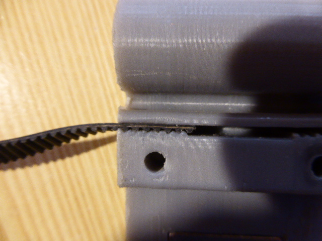
I had an interesting failure in UMMD recently. The Z axis belts kept getting floppy a couple days after I tensioned them. I took them off the machine to see what was going on, expecting to see that the steel wires in the core were broken, but that wasn't the problem. This was:
The belt clamp design uses a short segment of belt to lock the ends of the main belts into the clamps, like this:
I have redesigned the clamps to fold the ends of the belt back on themselves:
The belts will fit into the clamp similar to this.
Edited 1 time(s). Last edit at 12/10/2018 05:29PM by the_digital_dentist.
Ultra MegaMax Dominator 3D printer: [drmrehorst.blogspot.com]

The belt clamp design uses a short segment of belt to lock the ends of the main belts into the clamps, like this:

I have redesigned the clamps to fold the ends of the belt back on themselves:

The belts will fit into the clamp similar to this.
Edited 1 time(s). Last edit at 12/10/2018 05:29PM by the_digital_dentist.
Ultra MegaMax Dominator 3D printer: [drmrehorst.blogspot.com]
|
Re: How not to design a belt clamp December 10, 2018 02:57PM |
Registered: 12 years ago Posts: 1,450 |
I know we have discussed this back in 2016 but I use belts which are bonded together. I have not had a failure in that time and "pull it until it breaks" testing shows that the belt fails before the bond lets go. In the photo below the belts are bonded back to back as the rubber compound on the front side has a lubricant in it which may weaken the bond - the back side has no such lubricant. The adhesive that I used was "Black Witch" commonly used for patching wet suits.
Mike

Mike
|
Re: How not to design a belt clamp December 10, 2018 03:01PM |
Registered: 6 years ago Posts: 1,007 |
|
Re: How not to design a belt clamp December 12, 2018 04:48PM |
Registered: 9 years ago Posts: 752 |
Agreed, the take away here is to clamp on the wires, not the pu profile. A loop should half the force on the pu. Not sure if the tight loop is a problem for the steel wire. Only one way to find out
--
Kind regards
Imqqmi
NFAN CoreXY printer:
[reprap.org]
--
Kind regards
Imqqmi
NFAN CoreXY printer:
[reprap.org]
|
Re: How not to design a belt clamp December 12, 2018 05:19PM |
Registered: 8 years ago Posts: 1,671 |
|
Re: How not to design a belt clamp December 12, 2018 06:00PM |
Registered: 9 years ago Posts: 978 |
|
Re: How not to design a belt clamp December 14, 2018 04:01PM |
Registered: 8 years ago Posts: 601 |
Surely your new design causes the same problem? It is still inherently the same design, just curved around a post. I often find the post design is flawed as the post bends in the direction of the belts, eventually causing a slight mismatch of the teeth and some slip. Having said this though, I use a similar design on my own printer and it is one of the best clamping systems I've found so far.
I've often thought the best design would be to have a mating 'lid' that helps to secure the posts from both sides (or possibly use an M5 bolt in place of a printed post in the same design).
As I write this though, it occurs to me that maybe a small, metal, free-floating pin would work better as the belts would pull it into the tightest point, essentially adding another clamping force and removing any bend in a fixed post.
Edited 1 time(s). Last edit at 12/14/2018 04:03PM by Origamib.
|
Re: How not to design a belt clamp December 14, 2018 10:12PM |
Registered: 11 years ago Posts: 5,780 |
Here's the new one, printed. The original was pulling only on the end of the belt which could slide on the steel core wires and stretch. This "new" old design loops the belt back on itself- there's a much longer piece of belt to try to slide, it's wrapped around a post, and then locked in by the same piece of belt. It's definitely not the same. A similar design has been in use in the X axis of SoM for about 5 years with no failure. Even if the post breaks free, it will still do its job because it can't fit through the slot that the belt passes through.
I'm rebuilding SoM's Y axis and took out the ball screw drive and replaced it with a belt. I designed two belt clamps for SoM's Y axis. The first, which I ended up not using, is a single piece that anchors both ends of the belt using steel pins:
These are the belt clamps I ended up using- also self locking. This design engages more belt teeth and requires less vertical space. Splitting it into two pieces reduces the possibility of backlash:
It's amazing how much time and energy you can devote to little stuff like this.
Edited 1 time(s). Last edit at 12/14/2018 10:12PM by the_digital_dentist.
Ultra MegaMax Dominator 3D printer: [drmrehorst.blogspot.com]

I'm rebuilding SoM's Y axis and took out the ball screw drive and replaced it with a belt. I designed two belt clamps for SoM's Y axis. The first, which I ended up not using, is a single piece that anchors both ends of the belt using steel pins:

These are the belt clamps I ended up using- also self locking. This design engages more belt teeth and requires less vertical space. Splitting it into two pieces reduces the possibility of backlash:

It's amazing how much time and energy you can devote to little stuff like this.
Edited 1 time(s). Last edit at 12/14/2018 10:12PM by the_digital_dentist.
Ultra MegaMax Dominator 3D printer: [drmrehorst.blogspot.com]
|
Re: How not to design a belt clamp December 15, 2018 02:46AM |
Registered: 8 years ago Posts: 5,232 |
I like the idea of the floating pin!
But when it is able to spin, it only transfers the pulling force to the teeth_in_teeth section. Then it's possible again to rip the rubber and steelcore apart.
I assume there is not much clamping force in that section?
Seems, the fibre core belts score again.
Just thought, maybe a small wooden dowel pin would match the 2mm toothpattern? Or a square pin which can't spin?
|
Re: How not to design a belt clamp December 15, 2018 07:10AM |
Registered: 5 years ago Posts: 62 |
Yes this also looks like a poor idea durability wise.
I agree that iteration is functionally the same as your original.
Switching to Aramid core belt as MKSA suggested is a reasonable idea if you want to use this style of clamp.
The only reason your clamps work at all is the incidental friction between the rubber and the steel core, which could vary from brand to brand.
Rather then "devote" any more time and energy in a proven poor design, leave the "tail" section of the belt longer. Maybe fold it upon itself and zip tie it down. It's a half baked solution for your half baked problem.
The length of the tail has way more to do with the rate of failure then any of your revisions. This makes all this over engineering stuff complete nonsense when a lazy person with a 10 cm tail and a single zip tie can make a more reliable joint right?
|
Re: How not to design a belt clamp December 15, 2018 07:18AM |
Registered: 11 years ago Posts: 5,780 |
I think that the problem with the original design was that it only grabbed the last few teeth of the belt, and the path was straight. This grabs more of the belt, and the bends that the belt makes in wrapping around either the printed post or the steel pin and then back into the plastic will add a lot of friction. The smaller pin may actually be better for this purpose. With the Y axis clamps I am most afraid that the plastic will split on the layer lines and let go, but I'm not too concerned about it. I tried removing the steel pin after putting tension on the belt- there's a huge amount of friction there. I had to twist it with pliers to pull it out even after I released the tension on the belt.
I'm switching to glass core belt in UMMD's Z axis (pending stretch testing) because I don't trust that the top pulley diameter is sufficient to keep the steel cores healthy. SoM's Y axis may end up with two belts in parallel depending of how prints look.
Ultra MegaMax Dominator 3D printer: [drmrehorst.blogspot.com]
|
Re: How not to design a belt clamp December 17, 2018 03:44AM |
Registered: 6 years ago Posts: 1,007 |
Here is how I attach these GT2, didn't find anything simpler and more compact. For steel core belts, it should be sized to accommodate its bigger thickness and have a few more teeth.. To hold the steel wires, strip the belt to expose about 8mm steel wires then bend them along the smooth side and squeeze in the slot. I tried it, it is OK although I don't use them currently.
"A comical prototype doesn't mean a dumb idea is possible" (Thunderf00t)
"A comical prototype doesn't mean a dumb idea is possible" (Thunderf00t)
|
Re: How not to design a belt clamp December 17, 2018 07:09AM |
Registered: 11 years ago Posts: 5,780 |
Here's something simpler and probably more reliable than printed teeth relying on the squeeze provided by the plastic:
This would have the same problem that my original clamp had with steel core belts, except that more clamping force could be applied and more teeth engaged, so the sliding friction of the rubber on the steel wire would be higher. Maybe high enough, maybe not.
I have put the new clamps and glass core belt on the machine and will be load-stretch testing it this evening. It will be interesting to compare the steel core with the glass core stretch.
Ultra MegaMax Dominator 3D printer: [drmrehorst.blogspot.com]
|
Re: How not to design a belt clamp December 17, 2018 07:20AM |
Registered: 6 years ago Posts: 1,007 |
Of course metallic clamps like these would be sturdier than printed plastic ones.
Now you have to integrate them. If in a printed part, no much gain isn't ? Of course for a full metal build, they are justified. More so with steel core belt.
The printed one I made integrate in the "printed" part and all is strong enough, able to withstand the specified GT2 tension plus work load.
Now for the steel belt, expose the steel wires (heat gun plus pliers, easy), fold them and clamp.
"A comical prototype doesn't mean a dumb idea is possible" (Thunderf00t)
|
Re: How not to design a belt clamp December 17, 2018 09:10AM |
Registered: 8 years ago Posts: 1,671 |

I wanted those metal ones in the beginning but couldnt see how I would mount them as the only hole seems to be for clamping
|
Re: How not to design a belt clamp December 17, 2018 09:25AM |
Registered: 6 years ago Posts: 1,007 |

|
Re: How not to design a belt clamp December 17, 2018 09:43AM |
Registered: 11 years ago Posts: 5,780 |
This has been working on SoM's X axis for at least 5 years:
Ultra MegaMax Dominator 3D printer: [drmrehorst.blogspot.com]

Ultra MegaMax Dominator 3D printer: [drmrehorst.blogspot.com]
|
Re: How not to design a belt clamp December 17, 2018 10:00AM |
Registered: 8 years ago Posts: 1,671 |
Quote
MKSA
Quote
MechaBits
I wanted those metal ones in the beginning but couldnt see how I would mount them as the only hole seems to be for clamping
So just CLAMP it to the part "et voila "
you mean clamp it to the spacer you'll probably have to make(as you said)...but then it's not very tension friendly, no easy adjustment.
Edited 1 time(s). Last edit at 12/17/2018 10:00AM by MechaBits.
|
Re: How not to design a belt clamp December 17, 2018 10:20AM |
Registered: 11 years ago Posts: 5,780 |
The aluminum part is a clamp, not a tensioner. Tension has to be applied by other means such as moving a motor mount or end pulley. It's possible but not always desirable to combine the two functions.
Ultra MegaMax Dominator 3D printer: [drmrehorst.blogspot.com]
Ultra MegaMax Dominator 3D printer: [drmrehorst.blogspot.com]
|
Re: How not to design a belt clamp December 17, 2018 11:32AM |
Registered: 8 years ago Posts: 1,671 |
Sorry, only registered users may post in this forum.