designing prints with meshing gears in mind
Posted by oldmanbeefjerky
|
designing prints with meshing gears in mind February 16, 2019 03:09AM |
Registered: 11 years ago Posts: 7 |
Does anyone know any good resources for how to design things, like in general, for 3D printing or not (but mostly 3D printing) where youll be using gears?
Also, how to mount motors into a build as well.
A few times ive tried printing things that required a normal DC motor and the end result was wobbly and/or noisy, gears did not mesh well, were at weird angles, basically i had no idea what i was dong and yet, i couldnt find any resources to lay out how to design things with moving parts. With metal its all well and good to just do whatever, with proper injection molded or otherwise solid plastic its also easy, but printed, nothing really has any decent amount of structural integrity, 9/10 times no matter what print settings you use, basic geometric shapes that operate mechanically could be outdone by legos.
|
Re: designing prints with meshing gears in mind February 16, 2019 08:21AM |
Registered: 5 years ago Posts: 32 |
I come from a mechanical engineering background and I've struggled with this type of problem quite a bit too. When we design something to be machined from metal or injection molded we're working with very precise tolerances but the average 3D printer plays by a slightly different set of rules.
When we slice something we have several confounding factors that don't occur with a machined part. The accuracy of a printer is not defined purely by the print resolution settings, there's an array of confounding factors that all contribute to the final accuracy of the print, micro steps the drivers are running, print resolution and calibration of axes being the main ones before the slicer translates the model into G code and introduces its own deviations from the design to generate viable G code.
For me designing mating parts like gears or threads etc is a bit of an educated guess in many respects. I start with a set of tolerances I'd use for a metal or an injection molded part and then tinker with clearances until the parts operate as planned. Those clearances differ sightly for the 4 printers I have but in general I have to use much larger clearances than I would for machined parts and/or be prepared to drive the moving parts together so they wear in & work properly.
Edited 3 time(s). Last edit at 02/16/2019 05:37PM by Shreks donkey.
|
Re: designing prints with meshing gears in mind February 16, 2019 09:57AM |
Registered: 11 years ago Posts: 5,780 |
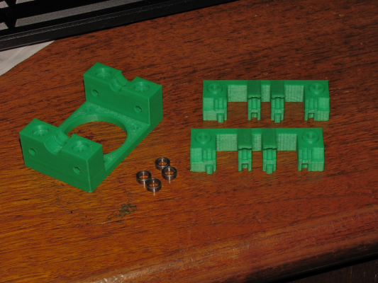
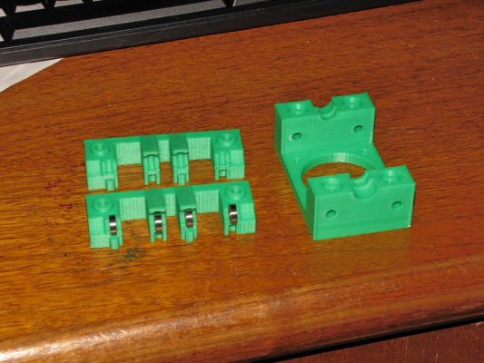
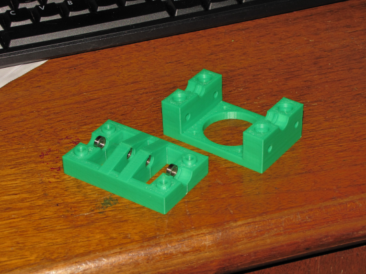
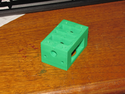
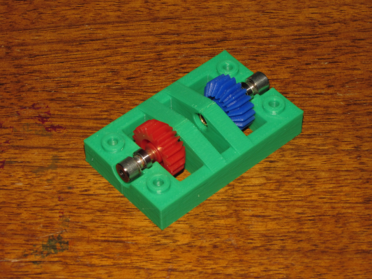
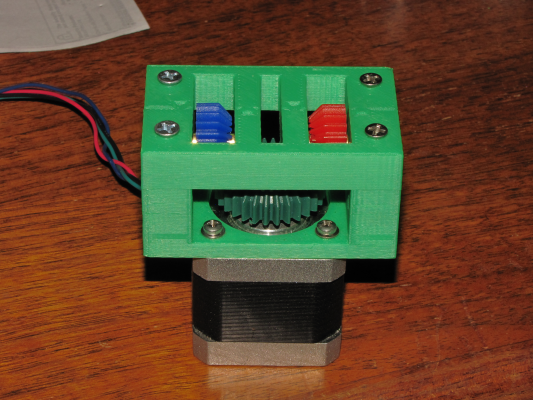
I do this sort of thing once in a while. What I find works best is to first make CAD models of all the non printed parts, including enough detail as needed to mount and align the parts. You'll need a decent caliper! Then I make as many test prints as needed to set spacing between things like gear shafts so they will mesh properly in the final part design. Depending on how big the item is, you can often make multiple test pieces in one go with the spacing or hole sizes varying. Designing printed parts for accurate alignment often involves connecting multiple printed parts to each other and you have to ensure alignment is accurate. I usually add bosses with mating holes to ensure that the printed parts will line up with each other and non-printed parts. You can add steel pins that fit tightly in holes to ensure accurate alignment of parts, too.
More here
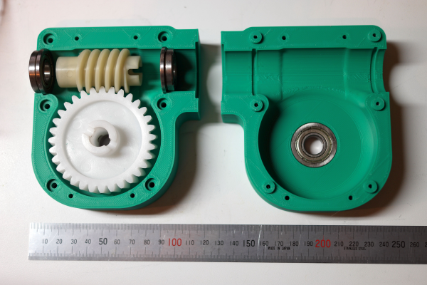
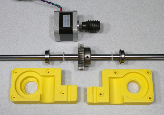
When I designed the worm gear boxes, I printed some test pieces with slightly different spacing between the shafts to ensure proper meshing. In the sand table project, I used a "square" aluminum tube for the X axis and it had to fit tightly into the Y axis bearing blocks, so I printed a part with a series of rectangular holes of different dimensions and then tested to see which would fit the way I wanted. In designing belt clamps that fold the belt and mesh the teeth you have to have the right slot width, so I printed a piece with slot widths from 1.0 to 3.0 mm in 0.1 mm steps. Now I can just use that part to check whatever belt I'm using (it always varies from one manufacturer to another) for the necessary slot width to hold the belt securely.
Edited 2 time(s). Last edit at 02/16/2019 01:30PM by the_digital_dentist.
Ultra MegaMax Dominator 3D printer: [drmrehorst.blogspot.com]
|
Re: designing prints with meshing gears in mind February 16, 2019 06:07PM |
Registered: 10 years ago Posts: 564 |
Keep in mind that most of the 3D printed gears you see tend to be huge Duplo block versions of their normal metal, or even molded gear counterparts. While calibration prints may show your printer to be accurate when printing fairly smooth regular surfaces, the vagaries of squirting at dragging molten plastic along the convoluted pathway that forms a set of gear teeth are going to fundamentally limit the accuracy of the surface. Thus, to get something that works reasonably well, it has to be scaled to the surface smoothness and accuracy of your 3D printing process.
One thing that does help, though, is the ability to easily print helical gears. The multiple points for contact provide a sort of averaging that can make gear mates seem tighter and they will run much smoother. Note, however, that this is a bit of an illusion because while you can achieve low backlash, the tooth stiffness around zero load (where you'd normally see backlash) is rather low. I designed a compound planetary gearbox that started off with straight spur gears and it was comically rough and very sloppy. Switching to helical gears was a huge improvement and made the design usable.
One thing that does help, though, is the ability to easily print helical gears. The multiple points for contact provide a sort of averaging that can make gear mates seem tighter and they will run much smoother. Note, however, that this is a bit of an illusion because while you can achieve low backlash, the tooth stiffness around zero load (where you'd normally see backlash) is rather low. I designed a compound planetary gearbox that started off with straight spur gears and it was comically rough and very sloppy. Switching to helical gears was a huge improvement and made the design usable.
|
Re: designing prints with meshing gears in mind February 16, 2019 06:19PM |
Registered: 9 years ago Posts: 752 |
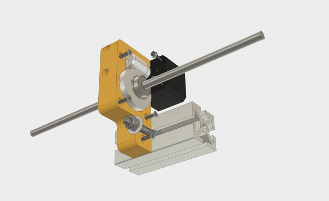
What I did for mating a motor with gear, with another gear is to make slots for the motor mount so that you've got some amount of adjustment available. Try finding models of 3D printed gears and see how others have done this. It can be quite challenging to come up with a tooth profile yourself and what it takes for teeth to mesh properly.
3D printed gears in plastic generally need larger dimensions as the extruded plastic is quite low resolution at typically 0.4 to 0.5mm. Humps and bumps will often mess up tight tolerances so design with that in mind. The same can be done with idlers and gears on a pin. The mounting of the pin can be made to slide or you can print multiple copies all with different offsets to try and see which fits best. Once you've got a feel for the tolerances you can rinse and repeat for other gear configurations.
--
Kind regards
Imqqmi
NFAN CoreXY printer:
[reprap.org]
|
Re: designing prints with meshing gears in mind February 17, 2019 02:53AM |
Registered: 5 years ago Posts: 32 |
As far as resources go for designing gears and gear trains goes. A few come to mind.
There's an online gear generator that's been up for a while but I think you have to pay a small fee to use it these days.
[geargenerator.com]
Inskape has a provision to design gears but I never persevered with it as it wasn't very intuitive to me.
Onshape has a gear generator feature script which I used recently to knock out a set of screw cutting gears for one of my lathes. I believe they have a gear train generator as well for designing multiple meshed gears. As we've all been saying though you will need some degree of trial and error to find workable tolerances for your printing setup.
I'm sure Fusion 360 would have a gear feature of some sort but I don't use it myself because I'm running Linux.
Edited 1 time(s). Last edit at 02/18/2019 06:04AM by Shreks donkey.
|
Re: designing prints with meshing gears in mind February 17, 2019 11:57AM |
Registered: 10 years ago Posts: 564 |
And here's another online gear generator that I've used: http://hessmer.org/gears/InvoluteSpurGearBuilder.html
|
Re: designing prints with meshing gears in mind February 17, 2019 05:09PM |
Registered: 9 years ago Posts: 483 |
|
Re: designing prints with meshing gears in mind February 18, 2019 03:39AM |
Registered: 6 years ago Posts: 1,007 |
Printed gears whose m is < 1 can barely be called "gears" and above 1 just barely usable. OK for toys, prototypes.
The Wade extruder is the good example of what you can get . Yet by using regular off the shelf gears one can achieve far better results with less bulk and weight.
And please, stay with metric gear, don't waste your time with the archaic inch, we are in the 21° century not the 19° [www.sdp-si.com]
Edited 1 time(s). Last edit at 02/18/2019 03:40AM by MKSA.
"A comical prototype doesn't mean a dumb idea is possible" (Thunderf00t)
The Wade extruder is the good example of what you can get . Yet by using regular off the shelf gears one can achieve far better results with less bulk and weight.
And please, stay with metric gear, don't waste your time with the archaic inch, we are in the 21° century not the 19°
 [www.sdp-si.com]
Edited 1 time(s). Last edit at 02/18/2019 03:40AM by MKSA.
"A comical prototype doesn't mean a dumb idea is possible" (Thunderf00t)
Sorry, only registered users may post in this forum.
