Presenting: The Pyr0-Piezo Z-Sensor! A self-calibrating piezoelectric sensor
Posted by pyr0ball
|
Presenting: The Pyr0-Piezo Z-Sensor! A self-calibrating piezoelectric sensor February 25, 2019 06:36PM |
Registered: 7 years ago Posts: 31 |
Hi there!
I recently published a project I’ve been working on for nearly two years, with the aim of solving the biggest issue facing cheap hobbyist 3D Printers: How to get a perfect first layer on any printer, using any type of hotend, and any print surface, even swap-able ones.
While this isn’t the first Piezoelectric z-sensor that’s been brought to the 3D Printing community, it is the first to incorporate an embedded microcontroller designed specifically for self-calibrating and conditioning the signal. Right now, the alpha boards being sent out into the wild don’t have full control over this circuit, but they already seem to produce good results. The Beta and final versions should only improve upon the principles and designs being tested now.
How the piezo z-sensor works: A small piezo element (commonly a 20mm or 27mm disk like the ones used in musical pickups) is fitted to a printer in such a way that when the nozzle touches the bed it undergoes a deformation or compression. When piezoelectric elements are subjected to mechanical forces in this way, they produce a charge. In the case of the z-sensor, this little blip of voltage produced by the piezo disk gets amplified, filtered, and conditioned by the Pyr0-Piezo circuit, then picked up by the board’s embedded MCU. The MCU then sends a z-trigger signal to the 3D Printer’s controller, and viola, you’ve got a Z-sensor. Since the MCU is using an interrupt pin for this function, it causes a delay of only a few microseonds, at most.
I’ve already finished about 12 sets of alpha (rev.1.x) boards that are going out to testers, but I will be looking for beta testers within the next month. If you’re interested, I’d appreciate a ping on the discord channel!
You can find source files on GitHub, Thingiverse, and my Discord’s #resources channel:
[github.com]
[www.thingiverse.com]
[www.thingiverse.com]
[discord.gg]
|
Re: Presenting: The Pyr0-Piezo Z-Sensor! A self-calibrating piezoelectric sensor February 26, 2019 02:21AM |
Registered: 6 years ago Posts: 1,007 |
|
Re: Presenting: The Pyr0-Piezo Z-Sensor! A self-calibrating piezoelectric sensor February 26, 2019 04:43AM |
Registered: 7 years ago Posts: 31 |
Yes, all of the documentation* is available on the GitHub under docs: [github.com]
*Finished documentation. I'm still working on fleshing it out
Edited 1 time(s). Last edit at 02/26/2019 04:44AM by pyr0ball.
*Finished documentation. I'm still working on fleshing it out
Edited 1 time(s). Last edit at 02/26/2019 04:44AM by pyr0ball.
|
Re: Presenting: The Pyr0-Piezo Z-Sensor! A self-calibrating piezoelectric sensor February 26, 2019 05:12PM |
Registered: 9 years ago Posts: 978 |
|
Re: Presenting: The Pyr0-Piezo Z-Sensor! A self-calibrating piezoelectric sensor February 26, 2019 09:24PM |
Registered: 7 years ago Posts: 31 |
Quote
frankvdh
I'd be keen to be a beta tester.
One question: is this suitable for under-bed mounting? I'd rather mount under my delta's bed than hang it, and the associated wiring, on the effector.
Although the FFC sounds great too!
I did see you ask over on the discord, but I wanted to respond here as well. Yes the standalone version of this sensor would be suitable for under-bed mounted piezo disks
|
Re: Presenting: The Pyr0-Piezo Z-Sensor! A self-calibrating piezoelectric sensor February 27, 2019 03:08AM |
Registered: 5 years ago Posts: 148 |
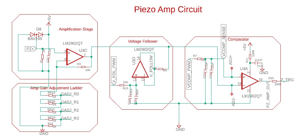
I wonder what it is you're trying to do with the outputs of U3C and U3D (see attached image) ?
Looks like you're trying to combine the outputs but very unsuccessfully. The output of U3D will have no effect (depending on the value of R4).
Looks like you're trying to combine the outputs but very unsuccessfully. The output of U3D will have no effect (depending on the value of R4).
|
Re: Presenting: The Pyr0-Piezo Z-Sensor! A self-calibrating piezoelectric sensor February 27, 2019 03:24AM |
Registered: 6 years ago Posts: 1,007 |
Quote
Pippy
I wonder what it is you're trying to do with the outputs of U3C and U3D (see attached image) ?
Looks like you're trying to combine the outputs but very unsuccessfully. The output of U3D will have no effect (depending on the value of R4).
True. I was going to make this remark too.
Anyway, why not to use the ADC of the controller and do all level, filtering in firmware ? Just one OP Amp and protection in the front. Look how DC42 did it in his smart effector.
"A comical prototype doesn't mean a dumb idea is possible" (Thunderf00t)
|
Re: Presenting: The Pyr0-Piezo Z-Sensor! A self-calibrating piezoelectric sensor February 27, 2019 03:27AM |
Registered: 5 years ago Posts: 148 |
Quote
MKSA
Anyway, why not to use the ADC of the controller and do all level, filtering in firmware ? Just one OP Amp and protection in the front. Look how DC42 did it in his smart effector.
I too thought this !
Using a little CPU should have made most of that analogue op-amp circuitry obsolete.
You don't even need an op-amp before the ADC, just a little RC filtering and diode protection. The signal from the piezo is very high in level.
|
Re: Presenting: The Pyr0-Piezo Z-Sensor! A self-calibrating piezoelectric sensor February 27, 2019 04:02AM |
Registered: 10 years ago Posts: 14,672 |
Quote
Pippy
You don't even need an op-amp before the ADC, just a little RC filtering and diode protection. The signal from the piezo is very high in level.
Exactly. Also the attiny processors have an optional ADC gain increase of up to x20. So the prototype piezo effector we designed used just an attiny processor, with no op amp. Whereas on the Smart Effector the signal from the strain gauge is measured in microvolts, so we do need the op amp.
Large delta printer [miscsolutions.wordpress.com], E3D tool changer, Robotdigg SCARA printer, Crane Quad and Ormerod
Disclosure: I design Duet electronics and work on RepRapFirmware, [duet3d.com].
|
Re: Presenting: The Pyr0-Piezo Z-Sensor! A self-calibrating piezoelectric sensor February 27, 2019 05:47AM |
Registered: 6 years ago Posts: 1,007 |
Quote
Pippy
Quote
MKSA
Anyway, why not to use the ADC of the controller and do all level, filtering in firmware ? Just one OP Amp and protection in the front. Look how DC42 did it in his smart effector.
I too thought this !
Using a little CPU should have made most of that analogue op-amp circuitry obsolete.
You don't even need an op-amp before the ADC, just a little RC filtering and diode protection. The signal from the piezo is very high in level.
OK if the controller can handle it. Note it wasn't to amplify the signal.
A piezo is a very high impedance high voltage source (In fact a cap with a minute amount of charge determined by the deflection).
Edited 1 time(s). Last edit at 02/27/2019 05:55AM by MKSA.
"A comical prototype doesn't mean a dumb idea is possible" (Thunderf00t)
|
Re: Presenting: The Pyr0-Piezo Z-Sensor! A self-calibrating piezoelectric sensor February 27, 2019 06:55AM |
Registered: 10 years ago Posts: 14,672 |
Quote
MKSA
Quote
Pippy
Quote
MKSA
Anyway, why not to use the ADC of the controller and do all level, filtering in firmware ? Just one OP Amp and protection in the front. Look how DC42 did it in his smart effector.
I too thought this !
Using a little CPU should have made most of that analogue op-amp circuitry obsolete.
You don't even need an op-amp before the ADC, just a little RC filtering and diode protection. The signal from the piezo is very high in level.
OK if the controller can handle it. Note it wasn't to amplify the signal.
A piezo is a very high impedance high voltage source (In fact a cap with a minute amount of charge determined by the deflection).
The attiny processor ADC inputs are OK with any two of high resistance source, high capacitance source, and fast changing input. The datasheet gives the ADC input resistance as 100Mohms typical and a few pF capacitance.
Large delta printer [miscsolutions.wordpress.com], E3D tool changer, Robotdigg SCARA printer, Crane Quad and Ormerod
Disclosure: I design Duet electronics and work on RepRapFirmware, [duet3d.com].
|
Re: Presenting: The Pyr0-Piezo Z-Sensor! A self-calibrating piezoelectric sensor February 27, 2019 06:56AM |
Registered: 5 years ago Posts: 148 |
Quote
dc42
Whereas on the Smart Effector the signal from the strain gauge is measured in microvolts, so we do need the op amp.
I never realised a length of PCB track could become a usable strain gauge as you've done with your touch sensor. Nice idea and application !
I guess as the PCB is ever so slightly deformed when the nozzle touches the bed, the lower layer PCB tracks expand ever so slightly, and the upper layer tracks do the opposite ?
|
Re: Presenting: The Pyr0-Piezo Z-Sensor! A self-calibrating piezoelectric sensor February 27, 2019 08:43AM |
Registered: 10 years ago Posts: 14,672 |
Quote
Pippy
I guess as the PCB is ever so slightly deformed when the nozzle touches the bed, the lower layer PCB tracks expand ever so slightly, and the upper layer tracks do the opposite ?
Correct. The deformation of the PCB + belt + motor elasticity is small, about 0.1mm, and most of that is probably the belt stretch plus motor elasticity. So the signal we measure is small too, about 25uV to trigger. It needs a very stable voltage source and a low noise amplifier to make it usable.
Large delta printer [miscsolutions.wordpress.com], E3D tool changer, Robotdigg SCARA printer, Crane Quad and Ormerod
Disclosure: I design Duet electronics and work on RepRapFirmware, [duet3d.com].
|
Re: Presenting: The Pyr0-Piezo Z-Sensor! A self-calibrating piezoelectric sensor February 27, 2019 10:43PM |
Registered: 7 years ago Posts: 31 |
Wow I need to check back in more often! Sorry for the delay in response.
I'll do my best to respond to everyone
The voltage follower in this part of the circuit is attached to the amplification output via a 1megaohm resistor. This has two functions, first, in Rev.1.x it pulls the level of the signal attached to the noninverting input of the comparator stage to midrail, this allows for an adjustable "virtual ground" point (I'll go into more detail as to why I'm doing this later). The second function it serves is as a delay to the recovery time of the circuit, which provides part of the filtering. It's sortof, not really, but kinda hysteresis. In any event in my testing it's shown to help filter out smaller blips.
In the Rev.2+ (the version you screenshotted) part of the self-calibration involves raising or lowering the "virtual ground" using PWM and a low-pass-filter, which in turn, allows for an additional point of control over auto-tuning.
To my understanding, dc42's smarteffector is using software to capture an analog signal and then process it. I didn't want to do it this way for two reasons:
I'll do my best to respond to everyone
Quote
Pippy
I wonder what it is you're trying to do with the outputs of U3C and U3D (see attached image) ?
Looks like you're trying to combine the outputs but very unsuccessfully. The output of U3D will have no effect (depending on the value of R4).
The voltage follower in this part of the circuit is attached to the amplification output via a 1megaohm resistor. This has two functions, first, in Rev.1.x it pulls the level of the signal attached to the noninverting input of the comparator stage to midrail, this allows for an adjustable "virtual ground" point (I'll go into more detail as to why I'm doing this later). The second function it serves is as a delay to the recovery time of the circuit, which provides part of the filtering. It's sortof, not really, but kinda hysteresis. In any event in my testing it's shown to help filter out smaller blips.
In the Rev.2+ (the version you screenshotted) part of the self-calibration involves raising or lowering the "virtual ground" using PWM and a low-pass-filter, which in turn, allows for an additional point of control over auto-tuning.
Quote
MKSA
Quote
Pippy
I wonder what it is you're trying to do with the outputs of U3C and U3D (see attached image) ?
Looks like you're trying to combine the outputs but very unsuccessfully. The output of U3D will have no effect (depending on the value of R4).
True. I was going to make this remark too.
Anyway, why not to use the ADC of the controller and do all level, filtering in firmware ? Just one OP Amp and protection in the front. Look how DC42 did it in his smart effector.
To my understanding, dc42's smarteffector is using software to capture an analog signal and then process it. I didn't want to do it this way for two reasons:
- I'm a hardware/electrical kind of guy, and my microcontroller programming skills are rudimentary at best. I wouldn't know how to implement what dc42 has done
- I'm using a hardware interrupt, which is VERY fast (like on the order of a few microseconds). From what I understand about dc42's effector, it's using an adc input and software to analyze the signal, which requires the adc pin to be actively polled
|
Re: Presenting: The Pyr0-Piezo Z-Sensor! A self-calibrating piezoelectric sensor February 27, 2019 10:47PM |
Registered: 7 years ago Posts: 31 |
Just an FYI, I'll be hosting a livestream later next week explaining how the circuit works. I'll also be recording it and will upload to youtube/gfycat for later review.
I'm also very much open to suggestions, or design inputs if you guys want to contribute. This is just the best way I know how to do what I wanted. If there's a better way, I'd be happy to incorporate it!
I'm also very much open to suggestions, or design inputs if you guys want to contribute. This is just the best way I know how to do what I wanted. If there's a better way, I'd be happy to incorporate it!
|
Re: Presenting: The Pyr0-Piezo Z-Sensor! A self-calibrating piezoelectric sensor February 28, 2019 02:14AM |
Registered: 10 years ago Posts: 14,672 |
Quote
pyr0ball
I'm using a hardware interrupt, which is VERY fast (like on the order of a few microseconds). From what I understand about dc42's effector, it's using an adc input and software to analyze the signal, which requires the adc pin to be actively polled
That's correct. But how fast does it need to be? We clock the ADC at 250kHz, giving a conversion time of 52us. We recommend probing at 20mm/sec. In 52us the probe travels about 1um. So that's the amount of jitter introduced by using the ADC.
Large delta printer [miscsolutions.wordpress.com], E3D tool changer, Robotdigg SCARA printer, Crane Quad and Ormerod
Disclosure: I design Duet electronics and work on RepRapFirmware, [duet3d.com].
|
Re: Presenting: The Pyr0-Piezo Z-Sensor! A self-calibrating piezoelectric sensor February 28, 2019 11:36AM |
Registered: 7 years ago Posts: 31 |
Quote
dc42
Quote
pyr0ball
I'm using a hardware interrupt, which is VERY fast (like on the order of a few microseconds). From what I understand about dc42's effector, it's using an adc input and software to analyze the signal, which requires the adc pin to be actively polled
That's correct. But how fast does it need to be? We clock the ADC at 250kHz, giving a conversion time of 52us. We recommend probing at 20mm/sec. In 52us the probe travels about 1um. So that's the amount of jitter introduced by using the ADC.
That's a very good question I hope to be able to answer after alpha/beta validation is done. At the moment I'm just not sure
|
Re: Presenting: The Pyr0-Piezo Z-Sensor! A self-calibrating piezoelectric sensor March 03, 2019 10:54AM |
Registered: 7 years ago Posts: 65 |
Quote
dc42
The attiny processor ADC inputs are OK with any two of high resistance source, high capacitance source, and fast changing input. The datasheet gives the ADC input resistance as 100Mohms typical and a few pF capacitance.
It was what I said two years ago here in the forum (https://reprap.org/forum/read.php?1,635075,760894#msg-760894), but it seems that some did not understand ... "DjDemonD" should remember well of my approach, because it was he who came in contact with me seeking a partnership. My "PiezProbe", which I've been seeing in Brazil for two years, uses only one Attiny and nothing else. Just develop the right software. Anyway, the use of attiny (without any other active component), is really a great solution.
|
Re: Presenting: The Pyr0-Piezo Z-Sensor! A self-calibrating piezoelectric sensor March 03, 2019 11:26AM |
Registered: 10 years ago Posts: 14,672 |
I made a mistake in my earlier post, I should have said:
The attiny processor ADC inputs are OK with any two of high resistance source, low capacitance source, and fast changing input. The datasheet gives the ADC input resistance as 100Mohms typical and a few pF capacitance.
So driving from a piezo is OK, because although the source resistance is high and the signal changes quite fast, the source capacitance is also high.
Large delta printer [miscsolutions.wordpress.com], E3D tool changer, Robotdigg SCARA printer, Crane Quad and Ormerod
Disclosure: I design Duet electronics and work on RepRapFirmware, [duet3d.com].
|
Re: Presenting: The Pyr0-Piezo Z-Sensor! A self-calibrating piezoelectric sensor March 03, 2019 12:24PM |
Registered: 6 years ago Posts: 1,863 |
Quote
pyr0ball
I was looking at the Direct Extruder FFC Breakout 1.0.0 schematics it floored be at first.
Was looking at the LM317DCY regulator and was confused by the use of OUTPUT_2 as a separate pin as you know they are internally connected.
Thous have never seen the distinction to lay it out as a 4 pin device. I have always seen the LM317 Layout as a 3 pin device.
Looked up the device and it indeed shows the LM317DCY SOT-223 as having 4 pins though the schematic layout shows it as a 3pin device.
This was intriguing for an Old School Tech, as they would start considering the heat dissipation tab a separate pin.
Thank You.
Noted in figure 24. of attached
Computer Programmer / Electronics Technician
|
Re: Presenting: The Pyr0-Piezo Z-Sensor! A self-calibrating piezoelectric sensor March 03, 2019 02:54PM |
Registered: 12 years ago Posts: 1,450 |
As DC42 and ECJ say, there is no strict need for either buffering or amplification. The earliest use of a piezo disk for contact detection that I have found is on little maze running robots. Having said that, I presently use a single op-amp to give some pre-filtering (10Hz to 500Hz) and a little gain (X2.5) as well as a fairly high input impedance. The reason for the last is that I use an 8 pin PIC microcontroller to do my signal detection and Microchip reccomends an input impedance of not more than 10k.
Mike
Mike
|
Re: Presenting: The Pyr0-Piezo Z-Sensor! A self-calibrating piezoelectric sensor March 03, 2019 04:39PM |
Registered: 10 years ago Posts: 14,672 |
You can ignore that Microchip recommendation of 10k if you understand the ADC and you know what you are doing. What's important is that the sampling capacitor (a few pF) can charge to the voltage you are trying to measure in the time you allow it. With 10K or less source resistance, that will always be the case. With higher source resistance, you can take additional measures to ensure it.
One of my working designs drives one of the ADC pins from a voltage divider comprising two 4M7 resistors, to measure the voltage of a 9V battery.
Edited 1 time(s). Last edit at 03/03/2019 04:40PM by dc42.
Large delta printer [miscsolutions.wordpress.com], E3D tool changer, Robotdigg SCARA printer, Crane Quad and Ormerod
Disclosure: I design Duet electronics and work on RepRapFirmware, [duet3d.com].
|
Re: Presenting: The Pyr0-Piezo Z-Sensor! A self-calibrating piezoelectric sensor September 02, 2019 11:33AM |
Registered: 12 years ago Posts: 227 |
Quote
ECJ
Quote
dc42
The attiny processor ADC inputs are OK with any two of high resistance source, high capacitance source, and fast changing input. The datasheet gives the ADC input resistance as 100Mohms typical and a few pF capacitance.
It was what I said two years ago here in the forum (https://reprap.org/forum/read.php?1,635075,760894#msg-760894), but it seems that some did not understand ... "DjDemonD" should remember well of my approach, because it was he who came in contact with me seeking a partnership. My "PiezProbe", which I've been seeing in Brazil for two years, uses only one Attiny and nothing else. Just develop the right software. Anyway, the use of attiny (without any other active component), is really a great solution.
Do you use selfcalibration or manual tuning?
|
Re: Presenting: The Pyr0-Piezo Z-Sensor! A self-calibrating piezoelectric sensor September 02, 2019 02:04PM |
Registered: 7 years ago Posts: 31 |
Well there's been a lot of development since my last post. Got a rudimentary website up, as well as a documentation site, and I'm in the process of building and shipping out beta units for testers.
I did some rough tests on my breadboard/oscilloscope last week and found that the trigger signal actuation takes about 21.5uS (microseconds) on average from the piezo input to signal output, so it's extremely fast.
Here's the docs site (still working on filling it out): [docs.pyroballpcbs.com]
I did some rough tests on my breadboard/oscilloscope last week and found that the trigger signal actuation takes about 21.5uS (microseconds) on average from the piezo input to signal output, so it's extremely fast.
Here's the docs site (still working on filling it out): [docs.pyroballpcbs.com]
|
Re: Presenting: The Pyr0-Piezo Z-Sensor! A self-calibrating piezoelectric sensor September 03, 2019 09:24AM |
Registered: 7 years ago Posts: 65 |
Quote
karabas
Quote
ECJ
Quote
dc42
The attiny processor ADC inputs are OK with any two of high resistance source, high capacitance source, and fast changing input. The datasheet gives the ADC input resistance as 100Mohms typical and a few pF capacitance.
It was what I said two years ago here in the forum (https://reprap.org/forum/read.php?1,635075,760894#msg-760894), but it seems that some did not understand ... "DjDemonD" should remember well of my approach, because it was he who came in contact with me seeking a partnership. My "PiezProbe", which I've been seeing in Brazil for two years, uses only one Attiny and nothing else. Just develop the right software. Anyway, the use of attiny (without any other active component), is really a great solution.
Do you use selfcalibration or manual tuning?
Self calibrated without any manual adjustment (since it was launched over 2 years ago).
Edited 1 time(s). Last edit at 09/03/2019 09:25AM by ECJ.
|
Re: Presenting: The Pyr0-Piezo Z-Sensor! A self-calibrating piezoelectric sensor September 06, 2019 04:25AM |
Registered: 6 years ago Posts: 1,007 |
Quote
ECJ
Quote
karabas
Quote
ECJ
Quote
dc42
The attiny processor ADC inputs are OK with any two of high resistance source, high capacitance source, and fast changing input. The datasheet gives the ADC input resistance as 100Mohms typical and a few pF capacitance.
It was what I said two years ago here in the forum (https://reprap.org/forum/read.php?1,635075,760894#msg-760894), but it seems that some did not understand ... "DjDemonD" should remember well of my approach, because it was he who came in contact with me seeking a partnership. My "PiezProbe", which I've been seeing in Brazil for two years, uses only one Attiny and nothing else. Just develop the right software. Anyway, the use of attiny (without any other active component), is really a great solution.
Do you use selfcalibration or manual tuning?
Self calibrated without any manual adjustment (since it was launched over 2 years ago).
How about some pictures, schematic, video in operation ? I understand you don't want to have it copied and I understand you, so no need to give the firmware.
"A comical prototype doesn't mean a dumb idea is possible" (Thunderf00t)
|
Re: Presenting: The Pyr0-Piezo Z-Sensor! A self-calibrating piezoelectric sensor September 06, 2019 10:45PM |
Registered: 7 years ago Posts: 31 |
I have a few things posted around online.
My apologies for not linking them here earlier, as I kinda neglected this post after making it.
Documentation site (under construction, still filling things out when I find time)
The github has all of the schematics, Eagle source files, drawings, diagrams, and 3D Models I've made so far
Gfycat of one of the alpha boards running on a Monoprice Delta Mini.
Another video of that at a different angle
A little animation I built in Fusion360 to show how to install the mount on a Creality print head
Fusion360 model of the EasyPiezi 2.1.1
Fusion 360 Models of the Pyr0-Piezo FFC Print Head Board, and the Controller Breakout Board
I also built a little script that parses my git commits and outputs a changelog to the documentation site
Im sure Im forgetting something, but hopefully that'll get you some ideas of where the project is at the moment
|
Re: Presenting: The Pyr0-Piezo Z-Sensor! A self-calibrating piezoelectric sensor September 07, 2019 03:57AM |
Registered: 6 years ago Posts: 1,007 |
|
Re: Presenting: The Pyr0-Piezo Z-Sensor! A self-calibrating piezoelectric sensor September 07, 2019 08:02AM |
Registered: 12 years ago Posts: 1,450 |
Quote
MKSA
............ Indeed, as written before, the use of a microcontroller to treat the pizeo signal is the way to go in this digital age.
As long as the production run is big enough to justify the programming time then microcontrollers are the way to go. My Op-amp/comparator based design cost about 25% more than my microcontroller one and the microcontroller (PIC16F1703) contains two op-amps and is able to drive LEDs without having a transistor to supply the current. That 14 pin microcontroller has enough processing power to do some remarkably sophisticated signal processing and can be tweaked or even completely reprogrammed without touching a soldering iron or turning a trim-pot
Mike
Edited 1 time(s). Last edit at 09/07/2019 01:42PM by leadinglights.
|
Re: Presenting: The Pyr0-Piezo Z-Sensor! A self-calibrating piezoelectric sensor September 07, 2019 04:36PM |
Registered: 7 years ago Posts: 65 |
Quote
MKSA
How about some pictures, schematic, video in operation ? I understand you don't want to have it copied and I understand you, so no need to give the firmware.
Ad where I make available for sale:
[produto.mercadolivre.com.br]
Specific to Ender 3 and CR-10:
[produto.mercadolivre.com.br]
Edited 1 time(s). Last edit at 09/07/2019 04:37PM by ECJ.

Sorry, only registered users may post in this forum.