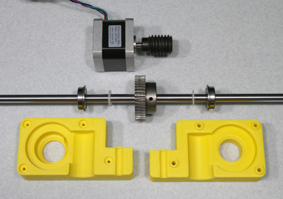
Belted Z axis conversion for Ender-3
Posted by klcjr89
|
Belted Z axis conversion for Ender-3 April 11, 2019 04:36PM |
Registered: 6 years ago Posts: 207 |
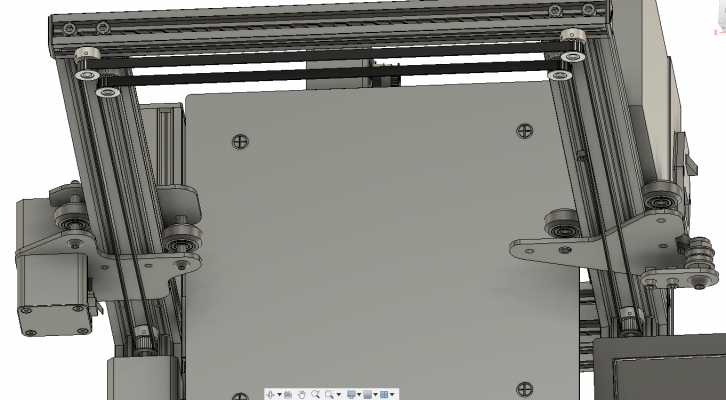
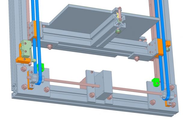
Hello, I am wanting to convert my Ender-3's Z axis to belt drive. I would like to ask if this quick mockup of the belt path would work. It will be single motor driven and will utilize a worm gear to prevent falling of the Z axis.
There will be four toothed pulleys and two smooth idlers.
Please note that I didn't model the worm gear area, this post is mainly about the belt path.
Pulleys, idlers, and belt will be genuine Gates.
Also, note that the screenshot depicts a closed loop belt, which is not what I'll be using. I will use an open ended belt and the ends of the belt will insert into some printed pieces.
Edited 6 time(s). Last edit at 04/11/2019 04:41PM by klcjr89.
|
Re: Belted Z axis conversion for Ender-3 April 11, 2019 05:29PM |
Registered: 6 years ago Posts: 1,863 |
|
Re: Belted Z axis conversion for Ender-3 April 11, 2019 10:34PM |
Registered: 11 years ago Posts: 5,780 |
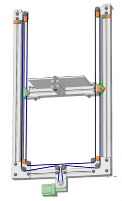
One of the early versions of the Z axis in my corexy printer was made with a single belt lifting two ends of the bed support, and had a worm gear to stop the bed from dropping.
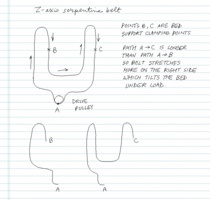
I never tested it by printing in that configuration because I came to realize a potential problem- the bed support was hanging from the belt, and the belt was anchored on the drive pulley. The length of belt from one side of the bed support to the drive pulley was much longer than the belt length to the other side. That meant that the side with the longer belt path would hang a little lower than the other side because of belt stretch. Since the path length varies depending on the Z axis position, you can't just offset one end relative to the other. As I said, I never tried printing with it but I did measure some difference by clamping a digital gauge to the frame on each side of the Z axis. In your printer, lifting the relatively light weight X axis up a relatively short Z axis, the tilt might not be enough to make a visible difference in prints
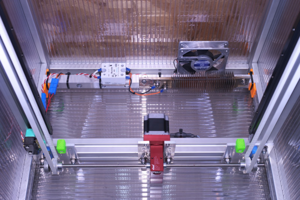
The asymmetry bothered me so I ultimately settled on a design that uses a worm gear drive with a long shaft and two drive pulleys at the ends of the shaft. There are two equal length, relatively short, belts instead of one long serpentine belt. Stretch will be equal in the two belts as long as their tensions are reasonably close to each other. The same type of design could easily be adapted to lifting an X axis. You could put the motor/worm gear at the top of the Z axis so there won't be any clearance issues with the bed.
Ultra MegaMax Dominator 3D printer: [drmrehorst.blogspot.com]
|
Re: Belted Z axis conversion for Ender-3 April 11, 2019 10:51PM |
Registered: 6 years ago Posts: 207 |
Quote
the_digital_dentist
One of the early versions of the Z axis in my corexy printer was made with a single belt lifting two ends of the bed support, and had a worm gear to stop the bed from dropping.
Mark, I was hoping you would reply and I'm glad you did!
 I will consider everything you talked about. Since I haven't committed to any particular design, I have plenty of time to figure it out.
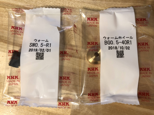
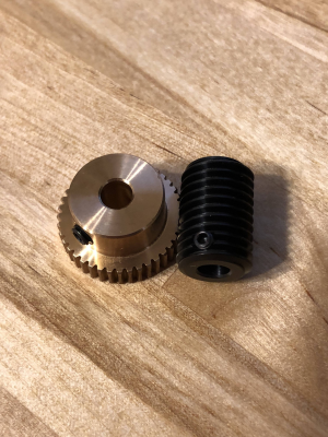
I ordered a Japanese 40:1 worm gear set as I didn't want to take a chance with a Chinese gear set and have irregular heights in the printed layers.
I really wanted a 20:1 set, but they didn't have those available. I figure that I can just halve the microstepping if necessary.
The worm and the worm wheel both have 5mm bores with set screws, so it should be easy to implement on the printer.
How exactly do I calculate the steps per mm with a worm drive setup with a 2GT belt?
Edited 3 time(s). Last edit at 04/11/2019 10:54PM by klcjr89.
|
Re: Belted Z axis conversion for Ender-3 April 12, 2019 02:09AM |
Registered: 5 years ago Posts: 148 |
Wonder why you decided to go with belts rather than leadscrews, it's interesting ?
I see people using the white steel reinfored belts when used on the Z axis, I guess to try to reduce ringing and stretching ?
I've used a 2:1 belt on my cart printer ..
(no 3D printed parts were used or harmed in the making of this printer)
Like in his Z axis ...
Belted Z axis
He's using this worm gear set from Ali ..
20:1 worm gear
Worm gear run in
Edited 7 time(s). Last edit at 04/12/2019 02:59AM by Pippy.
|
Re: Belted Z axis conversion for Ender-3 April 12, 2019 08:25AM |
Registered: 11 years ago Posts: 5,780 |
Quote
klcjr89
How exactly do I calculate the steps per mm with a worm drive setup with a 2GT belt?
Just divide by the gear ratio. Example: a 40 tooth pulley moves 80 mm/rev of the output shaft. Output shaft turns once for 20 turns of motor shaft. 20 turns of the motor shaft is 20 x200=4000 full steps. 16 usteps per full step means 4000x16= 64000 usteps moves the bed or x axis 80 mm. 64000/80 = 800 usteps/mm. 800/16 = 50 full steps/mm, so you'll want to set layer thickness and z hop on retraction to multiples of 20 um. Most of the time I print in 0.2 mm layers and I set Z hop to a multiple of 4 full steps - 0.8 mm to minimize Z artifacts.
Ultra MegaMax Dominator 3D printer: [drmrehorst.blogspot.com]
|
Re: Belted Z axis conversion for Ender-3 April 12, 2019 09:02AM |
Registered: 11 years ago Posts: 5,780 |
Quote
Pippy
Wonder why you decided to go with belts rather than leadscrews, it's interesting ?
I see people using the white steel reinfored belts when used on the Z axis, I guess to try to reduce ringing and stretching ?
Belts can't push the bed/X axis sideways like a bent lead screw can, so there's no potential for Z wobble. But belts are not without their issues. You need a gear reduction to achieve high resolution with belts, and to keep the bed from dropping like a rock when Z motor power is cut. Worm gears work well because they can be irreversible, depending on the gear ratio and a few other technical factors. Print quality is a direct function of the quality of the gears.
There's no issue with ringing in the Z axis, but stretch is a potential problem and steel core belts stretch less than glass core belts. That said, I have measured stretch with steel and glass core belts and found that the amount of stretch in either is inconsequential, at least the way I built it. With steel core 10 mm wide belts, at least the specific cheesy ones I used, the stretch amounts to no more than 1.2 um in any print layer, and that's based on covering the entire 300x300 mm bed with a 0.25 mm layer of plastic. I have since switched to 9mm wide Gates glass core belts and they stretch a little more - about 4 um maximum stretch in any layer. Most prints use a tiny fraction of the bed surface area, so the stretch will be masked by other imperfections in the printer/printing process.
The way I built the Z axis, the bed always has at least 800 mm of belt to hang from even when the bed is at the top of the Z axis. As the print gets taller, the length of belt between the bed supports and the drive pulley gets longer, so the belts will stretch more (still not enough to matter). You could easily reduce the belt stretch by building the Z axis so the drive pulleys are at the top of the Z axis. The you'd start with the bed hanging from very short lengths of belt and there would be almost no stretch. I tested it with the bed at about the middle of the Z axis, so it was hanging from about 1100 mm of belt. In a shorter Z axis printer, there will be less stretch.
Edited 1 time(s). Last edit at 04/12/2019 11:37AM by the_digital_dentist.
Ultra MegaMax Dominator 3D printer: [drmrehorst.blogspot.com]
|
Re: Belted Z axis conversion for Ender-3 April 12, 2019 09:03AM |
Registered: 6 years ago Posts: 63 |
If ya wanna try to make the worm gear yourself, I got a step file right here & a link to an imgur page explaining how to model your own. i think my worm gear here is only 1:13.
[www.thingiverse.com]
[www.thingiverse.com]
|
Re: Belted Z axis conversion for Ender-3 April 12, 2019 09:05AM |
Registered: 6 years ago Posts: 207 |
Quote
warbunniex
If ya wanna try to make the worm gear yourself, I got a step file right here & a link to an imgur page explaining how to model your own. i think my worm gear here is only 1:13.
[www.thingiverse.com]
As I said, I ordered a Japanese worm set. Chinese and printed gears don't seem that great.
|
Re: Belted Z axis conversion for Ender-3 April 12, 2019 11:28AM |
Registered: 11 years ago Posts: 5,780 |
Quote
warbunniex
If ya wanna try to make the worm gear yourself, I got a step file right here & a link to an imgur page explaining how to model your own. i think my worm gear here is only 1:13. [www.thingiverse.com]
3D printing can do a lot of things, but it can't do everything. A printed gear is never going to be accurate enough to drive the Z axis of a 3D printer. You have to be able to position and reposition the Z axis within a few tens of microns of the desired layer thickness or prints will come out looking awful. Every error in the surface of the worm gear will show up in the print and repeat with every rev of the worm. The same goes for the disc gear. Ugh! The rough surface of the printed plastic worm gear is going to grind against the rough surface of the printed plastic disc gear. For every turn of the disc, the worm will turn 5-100 times depending on the gear ratio you set up. How long can the worm gear last?
Ultra MegaMax Dominator 3D printer: [drmrehorst.blogspot.com]
|
Re: Belted Z axis conversion for Ender-3 April 12, 2019 08:02PM |
Registered: 6 years ago Posts: 207 |
Quote
the_digital_dentist
Just divide by the gear ratio. Example: a 40 tooth pulley moves 80 mm/rev of the output shaft. Output shaft turns once for 20 turns of motor shaft. 20 turns of the motor shaft is 20 x200=4000 full steps. 16 usteps per full step means 4000x16= 64000 usteps moves the bed or x axis 80 mm. 64000/80 = 800 usteps/mm. 800/16 = 50 full steps/mm, so you'll want to set layer thickness and z hop on retraction to multiples of 20 um. Most of the time I print in 0.2 mm layers and I set Z hop to a multiple of 4 full steps - 0.8 mm to minimize Z artifacts.
Mark, I am still having trouble trying to figure out the steps per mm if I use a 1.8º stepper, 40:1 worm gear, 2GT belt, and 20 tooth standard pulleys from Gates.
Thank you!
Edited 1 time(s). Last edit at 04/12/2019 08:03PM by klcjr89.
|
Re: Belted Z axis conversion for Ender-3 April 13, 2019 12:12AM |
Registered: 11 years ago Posts: 5,780 |
A 20 tooth pulley will move the bed 40 mm per rev. The motor is 200 steps/rev. 200/40 is 5 steps per mm. If it usteps at 16:1, 5 x 16 = 80 usteps/mm. If you use a 40:1 worm gear drive, 80 x 40 = 3200 usteps/mm.
Ultra MegaMax Dominator 3D printer: [drmrehorst.blogspot.com]
Ultra MegaMax Dominator 3D printer: [drmrehorst.blogspot.com]
|
Re: Belted Z axis conversion for Ender-3 April 13, 2019 12:13AM |
Registered: 6 years ago Posts: 207 |
Quote
the_digital_dentist
A 20 tooth pulley will move the bed 40 mm per rev. The motor is 200 steps/rev. 200/40 is 5 steps per mm. If it usteps at 16:1, 5 x 16 = 80 usteps/mm. If you use a 40:1 worm gear drive, 80 x 40 = 3200 usteps/mm.
Mark, thank you! Off topic, but I noticed you said you are using 9mm belts. Are 6mm inadequate? I saw in another thread you are in that even the 6mm 2GT Gates belts are overkill for 3D printers and was mentioned by this person here: [reprap.org]
Edited 3 time(s). Last edit at 04/13/2019 12:21AM by klcjr89.
|
Re: Belted Z axis conversion for Ender-3 April 13, 2019 12:39AM |
Registered: 11 years ago Posts: 5,780 |
In a printer that throws the heavy bed back and forth on the Y axis, or lifts it in the Z axis, I think wide belts are a good idea. If you're lifting the relatively lightweight X axis and the belts aren't going to be very long, 6mm wide belts should be fine.
Ultra MegaMax Dominator 3D printer: [drmrehorst.blogspot.com]
Ultra MegaMax Dominator 3D printer: [drmrehorst.blogspot.com]
|
Re: Belted Z axis conversion for Ender-3 April 13, 2019 01:42PM |
Registered: 6 years ago Posts: 207 |
Quote
the_digital_dentist
In a printer that throws the heavy bed back and forth on the Y axis, or lifts it in the Z axis, I think wide belts are a good idea. If you're lifting the relatively lightweight X axis and the belts aren't going to be very long, 6mm wide belts should be fine.
Mark, off topic but speaking of the bed, is there much of a difference when switching from a 1/4" thick Mic-6 bed plate to a 5/16" Mic-6 plate? I have 1/4" right now.
Thank you!
|
Re: Belted Z axis conversion for Ender-3 April 13, 2019 01:59PM |
Registered: 11 years ago Posts: 5,780 |
No difference that I have seen with 300 x300 mm plates.
Ultra MegaMax Dominator 3D printer: [drmrehorst.blogspot.com]
Ultra MegaMax Dominator 3D printer: [drmrehorst.blogspot.com]
|
Re: Belted Z axis conversion for Ender-3 April 13, 2019 02:00PM |
Registered: 6 years ago Posts: 207 |
|
Re: Belted Z axis conversion for Ender-3 April 14, 2019 07:54PM |
Registered: 6 years ago Posts: 207 |
|
Re: Belted Z axis conversion for Ender-3 April 16, 2019 03:18AM |
Registered: 9 years ago Posts: 383 |
|
Re: Belted Z axis conversion for Ender-3 April 16, 2019 02:52PM |
Registered: 6 years ago Posts: 207 |
The worm gear and worm have arrived, and I must say the quality is very good. 

|
Re: Belted Z axis conversion for Ender-3 April 16, 2019 09:31PM |
Registered: 6 years ago Posts: 1,007 |
Quote
WesBrooks
Any measurements on the level of backlash on a standard direct drive GT2 belt, belt reduction, and worm reduction?
I had been thinking about belt reduction on the x/y for small nozzle stuff. Worm would be neater, but I'm concerned aboit backlash.
Backlash is not an issue unless one use auto bed leveling. If ABL is used, then the machine has other issues anyway. Lead screw also have backlash.
Belts for z make sense for a tall machine. Hard to get long straight lead screws for a decent price.
For X and Y, I wouldn't use worm gear. 0.9° steppers or compound pulleys could be used : [www.wired.com] just twice that as you have to go both ways.
What you gain in resolution, you loose in speed, accel .
With the standard set up, GT2 and 20 teeth, my carriage plus direct drive and hot end (220g) can move safely at 300mm/s for non print move and the resolution is enough.
So I didn't try it. Easy to do though.
Edited 1 time(s). Last edit at 04/16/2019 09:36PM by MKSA.
"A comical prototype doesn't mean a dumb idea is possible" (Thunderf00t)
|
Re: Belted Z axis conversion for Ender-3 April 17, 2019 01:55AM |
Registered: 9 years ago Posts: 383 |
Edit: This is not intended as confrontational. If it reads like that it was not intended, I'm just trying to soak up plenty of information before investing in decent worm gear sets and suitable bearigs to eliminate the effect if the worm shuffling back and forth. Thanks for the previous responce, and reading through this.
I was mainly asking for figures and explaining my interest was in the x and y axis motion, and not initially in the z. However you can get anti backlash nuts for lead screws, and equally you can get anti backlash worms and gears. These are unlikely to eliminate backlash completely. Agreed that with a heavy z it's not an issue. I would like to use z-hop but would jus need to set the distance high enough to avoid backash issues.
You only loose in acceleration if the stepper motor is running close to it's physical limit of acceleration in an unloaded state. If the acceleration is being limited by the reflected inertia of the load, rather than the rotor then you would be able to increase acceleration relative to the stepper rotor to at least get close to the original acceleration.
With regards speed E3D'z blog on small nozzle work indicated that high even speeds of 60mm/sec were unobtainable. I will give the blog another read as I don't recall the detail being huge, and there were few if any references to external work.
Beyond these points my only work on attempting to validate resolution on these machines suggested that the major step size of the stepper was having a significant effect on positional accuracy over short distances. I intend to repeat this work on my little machines here and ask others to attempt the same soon. If this still is an issue any it is apparent on both my16 microstepping v0.6 duet and the higher microstepping generation 2 boards then when high speeds are not needed or are unobtainable then it would make sense to gear down to reduce the size of tis motor step so long as no other ssue introduced by the gearing is greater than that bring solved.
I've already commented about speed in relation to printing, but it is worth saying that reducing jumo speed could have a negative effect on build rates on small nozzle work. I'm working on a build time estimator that breaks the build time intovtime spent accelerating, travelling, prinying etc so I can be sure I'm not causing significant issues.
Out of interest what test parts do you use to verify resolution or are you referring to calculated resolution?
Edited 3 time(s). Last edit at 04/17/2019 12:31PM by WesBrooks.
Quote
MKSA
Lead screw also have backlash.
I was mainly asking for figures and explaining my interest was in the x and y axis motion, and not initially in the z. However you can get anti backlash nuts for lead screws, and equally you can get anti backlash worms and gears. These are unlikely to eliminate backlash completely. Agreed that with a heavy z it's not an issue. I would like to use z-hop but would jus need to set the distance high enough to avoid backash issues.
Quote
MKSA
For X and Y, I wouldn't use worm gear...
What you gain in resolution, you loose in speed, accel .
You only loose in acceleration if the stepper motor is running close to it's physical limit of acceleration in an unloaded state. If the acceleration is being limited by the reflected inertia of the load, rather than the rotor then you would be able to increase acceleration relative to the stepper rotor to at least get close to the original acceleration.
With regards speed E3D'z blog on small nozzle work indicated that high even speeds of 60mm/sec were unobtainable. I will give the blog another read as I don't recall the detail being huge, and there were few if any references to external work.
Beyond these points my only work on attempting to validate resolution on these machines suggested that the major step size of the stepper was having a significant effect on positional accuracy over short distances. I intend to repeat this work on my little machines here and ask others to attempt the same soon. If this still is an issue any it is apparent on both my16 microstepping v0.6 duet and the higher microstepping generation 2 boards then when high speeds are not needed or are unobtainable then it would make sense to gear down to reduce the size of tis motor step so long as no other ssue introduced by the gearing is greater than that bring solved.
Quote
MKSA
With the standard set up, GT2 and 20 teeth, my carriage plus direct drive and hot end (220g) can move safely at 300mm/s for non print move and the resolution is enough.
So I didn't try it. Easy to do though.
I've already commented about speed in relation to printing, but it is worth saying that reducing jumo speed could have a negative effect on build rates on small nozzle work. I'm working on a build time estimator that breaks the build time intovtime spent accelerating, travelling, prinying etc so I can be sure I'm not causing significant issues.
Out of interest what test parts do you use to verify resolution or are you referring to calculated resolution?
Edited 3 time(s). Last edit at 04/17/2019 12:31PM by WesBrooks.
|
Re: Belted Z axis conversion for Ender-3 April 26, 2019 12:14PM |
Registered: 6 years ago Posts: 207 |
|
Re: Belted Z axis conversion for Ender-3 April 29, 2019 02:25PM |
Registered: 6 years ago Posts: 207 |
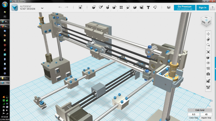
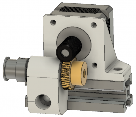
Finished designing the bearing blocks and stepper motor mount.
Edited 2 time(s). Last edit at 04/29/2019 04:49PM by klcjr89.
Edited 2 time(s). Last edit at 04/29/2019 04:49PM by klcjr89.
|
Re: Belted Z axis conversion for Ender-3 April 30, 2019 07:30AM |
Registered: 8 years ago Posts: 380 |
|
Re: Belted Z axis conversion for Ender-3 April 30, 2019 07:37AM |
Registered: 9 years ago Posts: 383 |
|
Re: Belted Z axis conversion for Ender-3 April 30, 2019 07:38AM |
Registered: 5 years ago Posts: 148 |
|
Re: Belted Z axis conversion for Ender-3 April 30, 2019 09:18AM |
Registered: 6 years ago Posts: 207 |
Quote
claustro
I am following this very interesting thread.
@klcjr89 can I ask you haw much you payed for the worm gear and the gear?
thank you
Andrea
The part numbers are in the pic: [reprap.org]
You can google them to find the best price for your country.

Edit: US prices:
Edited 1 time(s). Last edit at 04/30/2019 11:32AM by klcjr89.
|
Re: Belted Z axis conversion for Ender-3 April 30, 2019 12:10PM |
Registered: 11 years ago Posts: 5,780 |
I'm no fan of flat plate printed plastic motor mounts, and I'm not too sure about separating the motor mount/worm gear from the disc gear. The last thing you want is for the relative positions of the gears to change under load because that will change the position of whatever is being lifted by the belt(s). Flimsy motor and disc gear mounts will flex and do just that.
If you're going to use printed plastic parts to hold the gears, they need to be very bulky to ensure absolute minimal flex. This is what I used in an experimental printed worm gear box:
That tiny motor was lifting the 3.5 kg bed assembly in my printer at 10-15 mm per sec.
You may have to modify the layout of the machine to accomodate a really solid printed motor mount. That's life. You either build it so it will be solid and have a chance of working properly, or you do it half-assed and increase the probability of failure.
Edited 1 time(s). Last edit at 04/30/2019 12:13PM by the_digital_dentist.
Ultra MegaMax Dominator 3D printer: [drmrehorst.blogspot.com]
|
Re: Belted Z axis conversion for Ender-3 April 30, 2019 12:37PM |
Registered: 6 years ago Posts: 207 |
Quote
the_digital_dentist
I'm no fan of flat plate printed plastic motor mounts, and I'm not too sure about separating the motor mount/worm gear from the disc gear. The last thing you want is for the relative positions of the gears to change under load because that will change the position of whatever is being lifted by the belt(s). Flimsy motor and disc gear mounts will flex and do just that.
If you're going to use printed plastic parts to hold the gears, they need to be very bulky to ensure absolute minimal flex. This is what I used in an experimental printed worm gear box:
That tiny motor was lifting the 3.5 kg bed assembly in my printer at 10-15 mm per sec.
You may have to modify the layout of the machine to accomodate a really solid printed motor mount. That's life. You either build it so it will be solid and have a chance of working properly, or you do it half-assed and increase the probability of failure.
You didn't answer my question here: "Is it worth going thicker on printer beds exceeding 300mm^2?"
Also, there isn't any appreciable flex when putting weight on the pulleys.
Edited 1 time(s). Last edit at 04/30/2019 12:39PM by klcjr89.
Sorry, only registered users may post in this forum.
 )
)

