E-stepper microstepping quality
Posted by kasom
|
E-stepper microstepping quality March 09, 2020 04:13AM |
Registered: 9 years ago Posts: 31 |
E-stepper microstepping quality
Background story: I bought E3D Hemera and wrongly set vref to 0.5v on the stock Ender 3 board. Skipped step severely. Increased vref to 0.7v, calibrated e-steps, etc. Got a rough surface on all sides. Slowing down didn’t help.
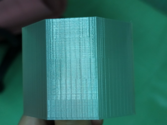
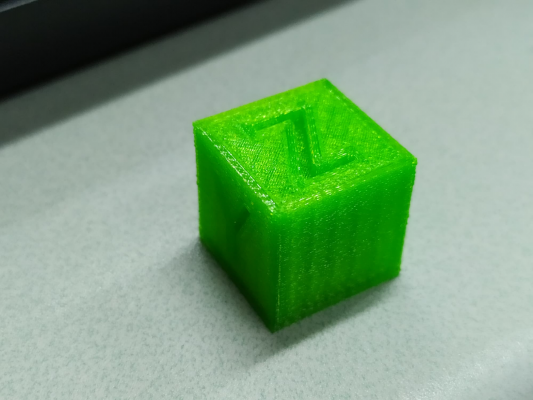
I printed a cube in vase mode and got salmon skin on all sides. Try varying the print speed. The salmon skin pattern stays the same, but it’s much stronger when printed slower. What!! I always think that print slower = better result. I tried to print even slower, and noticed that the extruder pulled the filament in not smoothly. It seems like the extruder only moves on full or half steps.
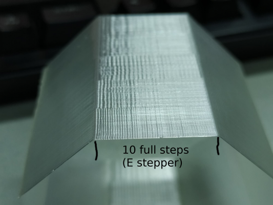
To verify this observation, I wrote a script to generate G-code that will align the extruder’s full step on every layer. I created a single wall octagon that each side has n * (mm per full step) long.
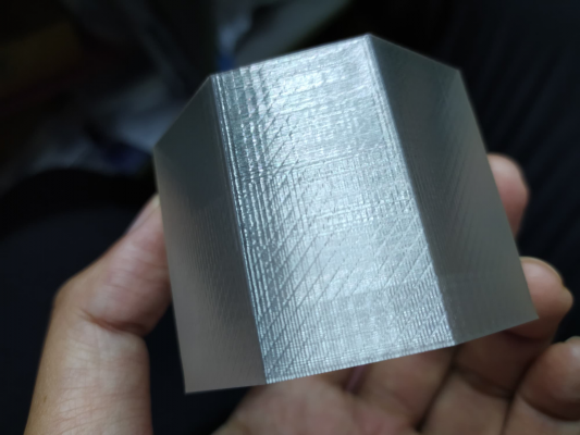
The result confirms that the pattern aligns with the E-stepper’s full step. I can produce a perfect vertical salmon skin when setting the extruder step per mm equal to the setting in the printer’s firmware. A slanting salmon skin can also be produced when setting the extruder step per mm slightly different from the firmware’s setting.
Correcting the vref to 0.96v helps a little. The pattern is still there. I’m waiting for SKR Mini E3 board. I’m still not sure if my Hemera has something wrong, or it is just the result of this particular combination with the Ender 3’s stock board.
Here is my script: G-code generator to test E-stepper microstepping
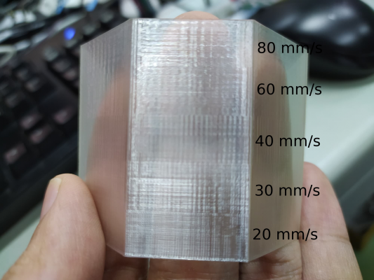
This octagon was printed at 20,30,40,60,80 mm/s (bottom to top). The pattern is the same for all sides.
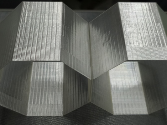
Left: incorrect vref at 0.7v, Right: 0.96v
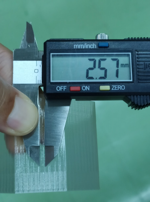
Using 394.87 step/mm (as set in firmware) the pattern width is 2.57mm. As calculated in the script.
slanting salmon skin. Set e-step per mm in script to 409, the firmware is set to 394.87.
Edited 2 time(s). Last edit at 03/09/2020 04:43AM by kasom.
|
Re: E-stepper microstepping quality March 09, 2020 05:15AM |
Admin Registered: 16 years ago Posts: 13,886 |
... yes, this is common with "underpowered" microstepping, where you notice the higher torque around the fullstep position related to the microstep-positions between.
When relaying on "real" microsetpping, I'm using "overpowered" steppers - e.g. with NEMA23-steppers with 2Nm torque and sometimes even with 5:1 gearbox reduction ...
Viktor
--------
Aufruf zum Projekt "Müll-freie Meere" - [reprap.org] -- Deutsche Facebook-Gruppe - [www.facebook.com]
Call for the project "garbage-free seas" - [reprap.org]
|
Re: E-stepper microstepping quality March 09, 2020 10:51AM |
Registered: 9 years ago Posts: 31 |
|
Re: E-stepper microstepping quality March 09, 2020 12:29PM |
Registered: 10 years ago Posts: 14,672 |
It's hard to advise you without knowing what the relationship between Vref on your driver is and the motor current. Maybe someone else knows what it is for the Ender 3 with the stock controller? The rated motor current of the Hemera is 1.33A.
Depending on what chip your stepper driver uses, diodes in series with the motor (aka TL Smoothers) may help. They typically help a lot when using DRV8825 drivers, and sometimes help when using A4988 drivers.
Edited 1 time(s). Last edit at 03/09/2020 12:30PM by dc42.
Large delta printer [miscsolutions.wordpress.com], E3D tool changer, Robotdigg SCARA printer, Crane Quad and Ormerod
Disclosure: I design Duet electronics and work on RepRapFirmware, [duet3d.com].
|
Re: E-stepper microstepping quality March 09, 2020 10:24PM |
Registered: 13 years ago Posts: 1,797 |
this issue is probably more visible because of what appears to be under extrusion.
but to be sure:
have you printed a xyz cube to test x,y,z size, and is it within your desired specs?
is your machine sturdy on the x and y rails? any slop or play. is the belt tight?
there is mention of an ender 3 board, but what printer is this from, does it have a sturdy frame? ( i didn't see a printer or model of printer named but it is possible i missed it in all the reading)
what nozzle are you using?
if those questions are answered to your own level of satisfaction then:
try upping the steps per mm even more. what stands out to me is the different wall thicknesses at various heights in the model's images.
there always is a small amount of slippage from feedstock, so this can be partially corrected by upping current to a point. the rest of the slippage is from stretching of the feedstock and various other small factors.
i would expect this to be less on a dual sided gear extrusion.
another thing to thing about is that different feedstocks have different force pressures from gear teeth, so diameter of circle of teeth is different slightly depending on feedstock, are you using a really soft pla? how deep. are the teeth bites?
i would up the steps per mm 10 steps at a time until you see a change, hopefully an improvement, if you up it and it gets worse, or starts to fold layers, then it could be something else.
|
Re: E-stepper microstepping quality March 09, 2020 11:28PM |
Registered: 9 years ago Posts: 31 |
Quote
dc42
It's hard to advise you without knowing what the relationship between Vref on your driver is and the motor current. Maybe someone else knows what it is for the Ender 3 with the stock controller? The rated motor current of the Hemera is 1.33A.
Depending on what chip your stepper driver uses, diodes in series with the motor (aka TL Smoothers) may help. They typically help a lot when using DRV8825 drivers, and sometimes help when using A4988 drivers.
From here and here the stock board uses A4988 with 0.1 Ohm Rsense.
Vref = 1.33 * 8 * .1 = 1.064
Cap at 90% max = 1.064 * .9 = 0.9576v
I'll do what you suggested. Ordering something from China right now will take a long time though.
Quote
jamesdanielv
this issue is probably more visible because of what appears to be under extrusion.
but to be sure:
have you printed a xyz cube to test x,y,z size, and is it within your desired specs?
is your machine sturdy on the x and y rails? any slop or play. is the belt tight?
there is mention of an ender 3 board, but what printer is this from, does it have a sturdy frame? ( i didn't see a printer or model of printer named but it is possible i missed it in all the reading)
what nozzle are you using?
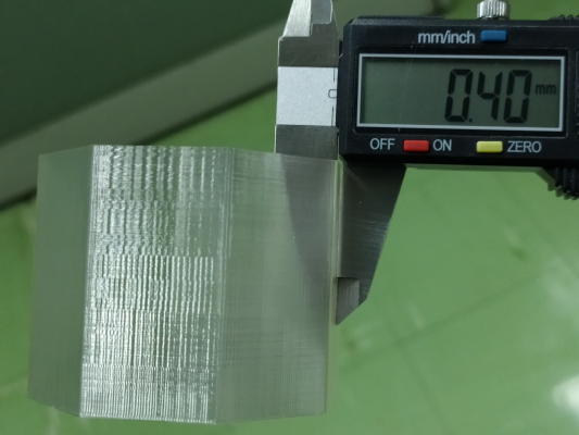
I think it extrude the right amount of filament. It's a single wall test, 0.4mm width.
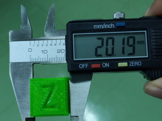
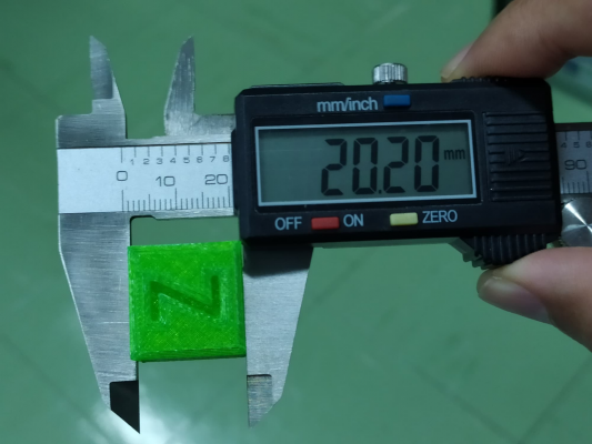
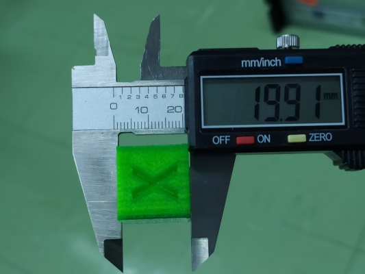
I have printed the calibration cube and some small objects. I'm satisfied with the results, except the rough skin on every side.
The machine is the Ender 3, all axis are sturdy, belt tight, no play. Right now I'm using a 0.3mm nozzle. (The 0.4mm nozzle that comes with the Hemera also exhibit the same pattern)
Quote
jamesdanielv
if those questions are answered to your own level of satisfaction then:
try upping the steps per mm even more. what stands out to me is the different wall thicknesses at various heights in the model's images.
there always is a small amount of slippage from feedstock, so this can be partially corrected by upping current to a point. the rest of the slippage is from stretching of the feedstock and various other small factors.
i would expect this to be less on a dual sided gear extrusion.
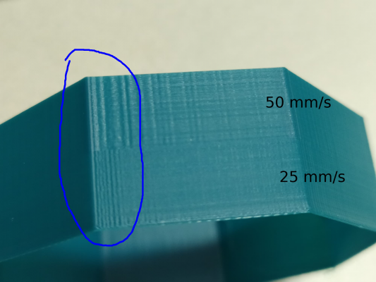
Are you referring to the differences in patterns as in this photo? They are printed at different speed. I have verified that they have the same thickness. The current is already set at 90% of the motor's maximum current. Upping the steps per mm would made it extrude more filament but I don't think it will help in this case. Anyway, I'll try it as I have nothing to do while waiting for the tl-smoother and SKR Mini E3 board.
Quote
jamesdanielv
another thing to thing about is that different feedstocks have different force pressures from gear teeth, so diameter of circle of teeth is different slightly depending on feedstock, are you using a really soft pla? how deep. are the teeth bites?
i would up the steps per mm 10 steps at a time until you see a change, hopefully an improvement, if you up it and it gets worse, or starts to fold layers, then it could be something else.
I've tried PETG, ASA and PLA, same results. I'll up the steps per mm and post the result.
|
Re: E-stepper microstepping quality March 10, 2020 12:51AM |
Registered: 9 years ago Posts: 31 |
|
Re: E-stepper microstepping quality March 10, 2020 02:25AM |
Registered: 13 years ago Posts: 1,797 |
thanks for that information, what happens if you lower the driver current to 60%, and then lower it as far as it can go and still print at correct speeds? its just a thing to try.
it could also be a side effect of a driver that can not deliver the current it is set for, from peak vs average current , and from thinner than spec traces, or a driver that is not designed to handle the current draw of the new motor.
if driver can not handle the current then the holding torque will dip a lot more than normal as the speed of the motor turns slow down and speed up,
possibly causing a spring like effect. this is because it does not have the power to maintain the higher voltages to the windings that normally would keep current constant. but i'm not really sure whats going on.
also the fact that increasing extrusion increased wall thickness, the extruder can handle the speed. i think you are correct in that this is somehow a defect from the current driver and or its settings.
Edited 3 time(s). Last edit at 03/10/2020 02:36AM by jamesdanielv.
|
Re: E-stepper microstepping quality March 10, 2020 11:28PM |
Registered: 9 years ago Posts: 31 |
Quote
jamesdanielv
thanks for that information, what happens if you lower the driver current to 60%, and then lower it as far as it can go and still print at correct speeds? its just a thing to try.
I will try that when the tl-smoothers arrive. My SKR Mini E3 has arrived so now I'm experimenting with it.
|
Re: E-stepper microstepping quality March 11, 2020 02:13AM |
Registered: 9 years ago Posts: 31 |
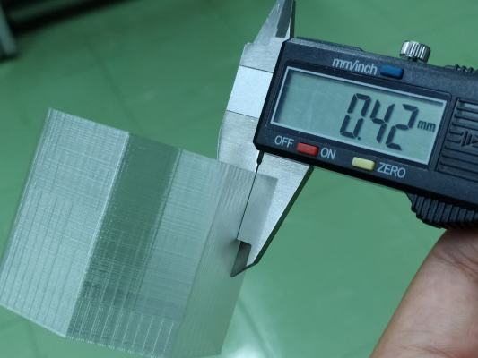
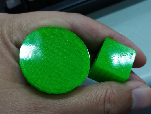
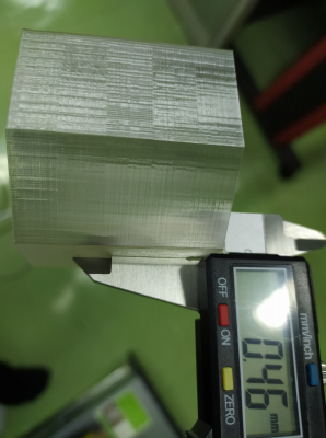
With the new board, the coarse pattern that aligned to the e-stepper's full step has gone. The fine pattern is still there, but it's much smoother than the old one when running my finger on it. Wall thickness is now spot on, it was 0.42 because of the rough texture on the surface.
At first I thought the fine pattern is due to microstepping so I expected (number of full step on each side) * (microstepping) = 10 * 16 = 160 teeth, or half of it = 10 * 8 = 80 teeth. But upon inspection, that is not the case. Printing faster also resulted in lesser number and less pronounced teeth.
At first I thought the fine pattern is due to microstepping so I expected (number of full step on each side) * (microstepping) = 10 * 16 = 160 teeth, or half of it = 10 * 8 = 80 teeth. But upon inspection, that is not the case. Printing faster also resulted in lesser number and less pronounced teeth.
|
Re: E-stepper microstepping quality March 13, 2020 02:36AM |
Registered: 9 years ago Posts: 31 |
Replaced X and Y motors with JK42HS34-1334A and 16 tooth pulleys.
At 20mm/s, compared to the old motor/pulley combination, the fine pattern is more spaced out and the surface is smoother. At 15mm/s the frequency of the pattern is 2x of that at 20mm/s.
Printing faster using opaque filament the fine pattern is not as noticeably as in the transparent filament. Ringing is more evident.
My conclusion is that the coarse pattern that align with the e-stepper's full step comes from the poor quality microstepping (solved by the TMC2209). The fine pattern might be the result from the combination of motor's torque, microstepping quality (again?) and the momentum of the moving hotend and heated bed. I've ordered some 0.9 degree motors, wonder if it can improve the result.
|
Re: E-stepper microstepping quality March 30, 2020 06:54AM |
Registered: 4 years ago Posts: 2 |
Hey there!
I've noticed a similar pattern across both my Hemera extruders, and I have a theory: this is due to the higher "command" of moving filament that the Hemera gears provide since we have such a short filament path and strong extrusion forces.
The pattern kinda lines up with the Hobb teeth profile (0.5*pi mm) of the Hemera. Around 1.57mm or thereabout. My printer is running on high precision rails on all axes with 9mm belts, a Duet WiFi and Duex5 controller, and has been finely tuned for belt slop/tension, smooth movement, etc. I've ruled out any other mechanical causes for the pattern appearing.
What set me off to this issue in the first place was the fact that the pattern is clearly seen on the top surface of any extrusion, and is consistently appearing in curved and straight segments (although with slightly different spacing). It is most visible with shiny filaments like PETG, and also with darker filaments such as black PLA. It has been driving me mad trying to fix, but I don't think it can be remedied with any hardware "tweaks" per se. Just take a look at an extruded line with lighting coming onto the surface at about a 30 degree angle, and the pattern should be visible at the top surface of the material.
I think if used with a Bowden configuration instead of direct, the length of filament between the extruder and the hot end would dampen out these imperfections significantly. I've also looked at older prints from a Titan Aero, and they have the same pattern on the top surface of perimeters, but to a less pronounced effect. I think this is one instance where an extra bit of slop in the filament would lead to smoother looking prints.
And FWIW, I've taken a look at images online of other direct-drive extruder prints. They all seem to exhibit this same pattern, to varying degrees. The key to seeing the slight dimpling is to look for specular highlights on flat surfaces, and you'll notice the tiny ripples.
I haven't confirmed this, but my digging certainly points in this direction. Changing microstepping would influence this behavior, but won't eradicate it entirely. I guess this is the 3D printer equivalent of "tooling marks" for the time being.
One last point: printing with more viscous filament (ie lower temperatures) makes this effect less visible..
Edited 2 time(s). Last edit at 03/30/2020 06:59AM by H2B.
|
Re: E-stepper microstepping quality March 30, 2020 07:51PM |
Registered: 8 years ago Posts: 1,671 |
|
Re: E-stepper microstepping quality March 30, 2020 09:42PM |
Registered: 4 years ago Posts: 2 |
Yup, it does not align at all with the belt profile (2GT). It seems to be a problem with the stepper on the Hemera not operating smoothly. We're talking about seeing ripples in the Z axis on the *top surface of perimeter lines.* Bed is solid, whole printer is very rigid, and pattern spacing seems to line up with the extruder Hobb profile of 20T Mod 0.5. Its a really odd issue that I haven't noticed this clearly on my other direct drive printer (prusa clone with a Titan Aero), but has been quite pronounced on this printer. Best way to see it is to print out a brim and shine a light at the surface from about a 30 degree angle. You'll see the surface of the lines rippling up and down (less than 0.01mm - can't measure them with my Mito caliper) and its very clear to the eye. It the same frequency across no matter what the print orientation or speed, except across curves where its slightly different (hence my thinking its from the extruder).
|
Re: E-stepper microstepping quality March 31, 2020 11:54AM |
Registered: 8 years ago Posts: 1,671 |
|
Re: E-stepper microstepping quality April 17, 2020 06:19PM |
Registered: 7 years ago Posts: 363 |
I'm a bit late to this topic. But had the thought (question) about what, if any, impact on quality would you have by reducing micro stepping and using gears to maintain the same theoretical resolution.
Obviously you would risk artifacts induced by any back lash as a result of the additional mechanical pieces. But it's an interesting theory I think. If full steps give best positioning and torque, using gearing for resolution, every step position would have the same benefits.
Well, just spit-balling thoughts. I'm not an engineer, any of you more experienced members here feel free to point out while my ideas wouldn't work.
Sorry, only registered users may post in this forum.
