Kinematic systems and linear guides
Posted by pandaym
|
Kinematic systems and linear guides July 08, 2020 04:50PM |
Registered: 3 years ago Posts: 8 |
Hi everyone,
After having dealt with different types of 3D printers, I am slowly preparing to design my own printer. I am a mechanical engineer, and therefore probably overthinking it a lot, but currently I am putting a lot of thought into the XYZ kinematics, and would like to hear your thoughts on the common concepts and potential alternatives.
I would like to share some of my views on kinematics, and where I am in the scoping process.
I personally think that the benefits of having isolated axes are really important, and that is exactly the reason why the Prusa i3 design is so popular. Having three axes that mechanically work independently l, means that aligning and adjustment is extremely forgiving. It is therefore also pretty straightforward to build a bed slinger without much of a performance bottleneck anywhere. That being said, slinging the bed starts to become increasingly challenging as the build volume grows.
The alternatives to the bed slinger cartesian seems to currently dominated by corexy. There are plenty advantages of a corexy setup, that most probably already know about. My main problem with it, is exactly the point from above, that the axes are not independent. Having axes that depend on each other means that their geometric relationships are super important, and any variances will be amplified greatly. So even though it is technically possible to balance out a corexy setup to be great, I personally would rather look into alternatives.
My current idea is therefore to go with a crossed gantry cartesian (probably has a name?). Not many printers seem to boast this motion type, and. Have only really seen it used in the Ultimaker series. This seems like the ideal choice based on my experiences for making a cartesian with a larger build volume that the i3 design “allows”.
What are your thoughts about kinematic systems and my opinions?
————-
When looking at linear guide systems, I have also been doing some thinking. It seems most people recommend the Hiwin style linear rails, but I personally see some issues with going that route. First of all, good rails cost a fortune and cheap clone alternatives are... well, just not something I enjoy working with. If I were to build a real industrial CNC machine, proper linear rails would definitely be my go to, but this is a very different use case. For linear rails to work as intended, it is critical to follow the design guidelines from the manufacturer. This includes things like having known reference points to constrain the rail to, and having a completely planar and rigid surface to install it on.
Though there are many alternatives to the linear rails, the common ones on 3D printers seem to be V wheels and rods. V wheels do have a lot of benefits in my opinion, similar to how the cartesian system have benefits, in that elements are decoupled. This means it is very flexible and forgiving, as it can be adjusted as needed. The downside is that the V wheels make for a system with A LOT of components, and one that is really hard to enclose. Rods on the other hand seems like a great way to have few components, easy to design with the right amount of constrains etc.
What are your thoughts on the linear guide systems?
————
So all in all, based on my personal experience, the ideal 3D printer design is pretty much an Ultimaker it seems. This might well be what I end up going for, and I am therefore also interested in getting as much inspiration as possible for this. Therefore I would also like to know if there are any public designs available for an Ultimaker style printer with a largeish bulldvolume (somewhere between 300x300 and 400x400).
|
Re: Kinematic systems and linear guides July 08, 2020 07:13PM |
Registered: 3 years ago Posts: 92 |
I do like the look of that crossed rail XY system. The moving bed is good for milling where you need high rigidity and movement is slow enough that momentum is negligible, but it amazes me 3D printers can yank it back and forth as well as they do when printing narrow zigzags. Also not good for tall skinny things.
What I don't like about the Ultimaker design is the cantilevered bed, especially if you're going to be printing large heavy things. I would prefer something like the Voron1 bed carriage, with 4 rods and two leadscrews, although it does increase the width quite a bit, and the cost for twice the components.
What I don't like about the Ultimaker design is the cantilevered bed, especially if you're going to be printing large heavy things. I would prefer something like the Voron1 bed carriage, with 4 rods and two leadscrews, although it does increase the width quite a bit, and the cost for twice the components.
|
Re: Kinematic systems and linear guides July 08, 2020 10:50PM |
Registered: 11 years ago Posts: 5,780 |
I have used linear guides in a bed flinger and a corexy machine. I would not build using any other type of guidance. Any time you use any sort of end supported guidance, either round rails or wheels in T or V-slot you have to worry about aligning the rails to each other in 3 dimensions. T and V slot rails are extruded, not milled and ground, so you never really know how straight or flat they are. Many machines use them and work fine, but the alignment problems - i.e. putting them parallel or square to each other is not easy. With linear guides, you can mount them on a piece of tooling plate and know that they will be on the same plane. Yes, to achieve all the manufacturer's specs on the guide you must mount it in a ground slot with a reference to butt it up against, and set another parallel by mounting a dial gauge on the bearing block, but the guides perform just fine without doing all that. Then the only alignment issue is to get them parallel in the plane on which they are mounted which is easy- bolt one down tight, mount a spacer on a bearing block and use that to set the other rail parallel to the first. In a corexy machine you set the rails square to each other before you install the belts. After you install the belts you make sure the rails are square again by manipulating the belt tension and you're done. For the X axis a single linear guide works fine so there are no concerns about getting two guides parallel in X.
I buy high quality surplus linear guides via ebay. It is not unusual to find NOS guides by NSK, THK, IKO, etc., for little more than the price of crappy HiWin knockoffs. Here's an example If you're designing and building one printer, you can use just about any size rail that's available for a good price. The 12 mm linear guides seem to be most common in the surplus market. The rails can be cut to required length using a cutoff wheel on a grinder. Some people have the idea that their design should be duplicated by anyone who can read their BOM posted in Thingiverse. They buy crappy HiWin knockoffs because other people will be able to get them easily/cheaply and the dimensions will be approximately the same no matter who actually makes the rail. Great.
This is the XY stage on my printer:
There is a 4040 t-slot subframe to which two pieces of cast tooling plate are bolted. The 8x24 mm Y axis guide rails go on the cast tooling plate, and the single 8 x 24 mm X axis guide rail mounts between them. This type of assembly can be dropped into a machine with any length Z axis. I used aluminum tubing to support the pulley axles at top and bottom to prevent them from flexing inward under belt tension. The assembly was designed to be used in a heated printer, so the X axis guide rail has an extra bearing block that allows the guide rail to slide a little as the frame expands and the Y axis rails move apart so it never binds. I have seen some forum posts from people who built corexy mechanisms using linear guides that bind when the temperature changes by 20C. I used large diameter skate wheel bearings for long life, quiet operation, and no print artifacts from belt teeth riding on smooth pulley surfaces. It's not the lowest possible moving mass mechanism, but it reliably produces high quality prints. Notice the minimal use of printed plastic parts (orange and yellow).
In my corexy printer, the only linear guides that bolt to t-slot are the Z axis rails. The t-slot is the type with a concave surface that is used to act as a locking mechanism for bolts that are mounting stuff on the t-slot. It does not provide a stable surface to mount a linear guide. For those I milled a shallow channel along the slots so that the guides would have a flat surface to sit on. It works well. You can get t-slot that has flat surfaces. They are extruded, not milled and ground, but if you think they're acceptable for wheeled carriages, they're fine for mounting linear guides.
Any printer worth the effort to design and build is worth the effort to enclose. If you build with wheeled carriages riding on the printer's frame, it becomes much more difficult to enclose in an esthetically acceptable way. Sure, you can just build a big insulated box over the whole thing, and that's fine for a machine that sits in a shop or garage, but a lot people like to keep the printer in their home or office where it will be seen by others, including wives. If you build using linear guides you can usually just bolt panels to the printer's frame which increases its rigidity and looks a lot better than a big, ugly box built around the printer.
Finally, if you price out the hardware you'll find that wheeled carriages aren't much cheaper than surplus linear guides.
Edited 2 time(s). Last edit at 07/08/2020 10:59PM by the_digital_dentist.
Ultra MegaMax Dominator 3D printer: [drmrehorst.blogspot.com]
I buy high quality surplus linear guides via ebay. It is not unusual to find NOS guides by NSK, THK, IKO, etc., for little more than the price of crappy HiWin knockoffs. Here's an example If you're designing and building one printer, you can use just about any size rail that's available for a good price. The 12 mm linear guides seem to be most common in the surplus market. The rails can be cut to required length using a cutoff wheel on a grinder. Some people have the idea that their design should be duplicated by anyone who can read their BOM posted in Thingiverse. They buy crappy HiWin knockoffs because other people will be able to get them easily/cheaply and the dimensions will be approximately the same no matter who actually makes the rail. Great.
This is the XY stage on my printer:

There is a 4040 t-slot subframe to which two pieces of cast tooling plate are bolted. The 8x24 mm Y axis guide rails go on the cast tooling plate, and the single 8 x 24 mm X axis guide rail mounts between them. This type of assembly can be dropped into a machine with any length Z axis. I used aluminum tubing to support the pulley axles at top and bottom to prevent them from flexing inward under belt tension. The assembly was designed to be used in a heated printer, so the X axis guide rail has an extra bearing block that allows the guide rail to slide a little as the frame expands and the Y axis rails move apart so it never binds. I have seen some forum posts from people who built corexy mechanisms using linear guides that bind when the temperature changes by 20C. I used large diameter skate wheel bearings for long life, quiet operation, and no print artifacts from belt teeth riding on smooth pulley surfaces. It's not the lowest possible moving mass mechanism, but it reliably produces high quality prints. Notice the minimal use of printed plastic parts (orange and yellow).
In my corexy printer, the only linear guides that bolt to t-slot are the Z axis rails. The t-slot is the type with a concave surface that is used to act as a locking mechanism for bolts that are mounting stuff on the t-slot. It does not provide a stable surface to mount a linear guide. For those I milled a shallow channel along the slots so that the guides would have a flat surface to sit on. It works well. You can get t-slot that has flat surfaces. They are extruded, not milled and ground, but if you think they're acceptable for wheeled carriages, they're fine for mounting linear guides.
Any printer worth the effort to design and build is worth the effort to enclose. If you build with wheeled carriages riding on the printer's frame, it becomes much more difficult to enclose in an esthetically acceptable way. Sure, you can just build a big insulated box over the whole thing, and that's fine for a machine that sits in a shop or garage, but a lot people like to keep the printer in their home or office where it will be seen by others, including wives. If you build using linear guides you can usually just bolt panels to the printer's frame which increases its rigidity and looks a lot better than a big, ugly box built around the printer.
Finally, if you price out the hardware you'll find that wheeled carriages aren't much cheaper than surplus linear guides.
Edited 2 time(s). Last edit at 07/08/2020 10:59PM by the_digital_dentist.
Ultra MegaMax Dominator 3D printer: [drmrehorst.blogspot.com]
|
Re: Kinematic systems and linear guides July 09, 2020 06:17AM |
Registered: 12 years ago Posts: 1,450 |
Hi Pandaym,
Having 3 axes working independently does intuitively seem the way to go. For myself I would rather build my next 3D printer from cast iron; filed, hand-scraped, and, if necessary, chewed into perfect flatness and squareness. The numbers however tell a different story: Many Delta printers made by happy amateurs achieve accuracy throughout the build volume not too far from the cast-iron machines of a few decades ago. This is done by having the power of the computer to correct the geometry of the construction and the flatness of the bed. The computer, or more accurately, the microcontroller, can also address many of the errors which are found in any kinematic mechanism. I must acknowledge that this is an unsatisfying opinion as I would rather be flint knapping than bit twiddling but I think my own rearguard action against the silicon overlords has been lost already.
My present printer slings the bed in both the X and Y axes on something like your crossed gantry. The reason for adopting this is that I rarely need a build volume grater than 200mm cube but do need lots of printer heads and other heavy bits on the printing end. Will I do it this way if I build another printer? No. I would build a CoreXY with automatic tool head changing. Maybe I would build a modified Delta with 3 hotends on a tiltable effector allowing each nozzle to be moved into the datum position with the others lifted clear of the print.
Or maybe I will adopt flint knapping as my next hobby
Mike
|
Re: Kinematic systems and linear guides July 09, 2020 07:15AM |
Registered: 3 years ago Posts: 8 |
Quote
dekutree64
I do like the look of that crossed rail XY system. The moving bed is good for milling where you need high rigidity and movement is slow enough that momentum is negligible, but it amazes me 3D printers can yank it back and forth as well as they do when printing narrow zigzags. Also not good for tall skinny things.
What I don't like about the Ultimaker design is the cantilevered bed, especially if you're going to be printing large heavy things. I would prefer something like the Voron1 bed carriage, with 4 rods and two leadscrews, although it does increase the width quite a bit, and the cost for twice the components.
Thank you very much for your reply.
I absolutely agree that it is amazing what a bed slinger can perform. I personally have a Prusa MK3S with Bear 2.1, Bondtech extruder and Phaetus Dragon hotend. I get so reliable and extremely high quality prints off this machine that I would not have expected from the kinematics design. Though my corexy on linear rails is not completely done - I have a strong feeling that printer will never outperform my Prusa, which is part of my bias on these things.
I also absolutely agree on the cantilevered Ultimaker bed - this part of their design they can keep to themselves. On my corexy I have 3 Z motors with lead screws on flexible couplers. This along with 2 linear rails feels like a solid Z setup, that I will probably bring over to my next printer.
Generally I am a fan of constructions that have the correct number of constrains - no more, no less, which is why the 3x leadscrew on flex couplers with 2x linear rails appeals to me.
|
Re: Kinematic systems and linear guides July 09, 2020 07:54AM |
Registered: 3 years ago Posts: 8 |
Quote
the_digital_dentist
I have used linear guides in a bed flinger and a corexy machine. I would not build using any other type of guidance. Any time you use any sort of end supported guidance, either round rails or wheels in T or V-slot you have to worry about aligning the rails to each other in 3 dimensions. T and V slot rails are extruded, not milled and ground, so you never really know how straight or flat they are. Many machines use them and work fine, but the alignment problems - i.e. putting them parallel or square to each other is not easy. With linear guides, you can mount them on a piece of tooling plate and know that they will be on the same plane. Yes, to achieve all the manufacturer's specs on the guide you must mount it in a ground slot with a reference to butt it up against, and set another parallel by mounting a dial gauge on the bearing block, but the guides perform just fine without doing all that. Then the only alignment issue is to get them parallel in the plane on which they are mounted which is easy- bolt one down tight, mount a spacer on a bearing block and use that to set the other rail parallel to the first. In a corexy machine you set the rails square to each other before you install the belts. After you install the belts you make sure the rails are square again by manipulating the belt tension and you're done. For the X axis a single linear guide works fine so there are no concerns about getting two guides parallel in X.
I buy high quality surplus linear guides via ebay. It is not unusual to find NOS guides by NSK, THK, IKO, etc., for little more than the price of crappy HiWin knockoffs. Here's an example If you're designing and building one printer, you can use just about any size rail that's available for a good price. The 12 mm linear guides seem to be most common in the surplus market. The rails can be cut to required length using a cutoff wheel on a grinder. Some people have the idea that their design should be duplicated by anyone who can read their BOM posted in Thingiverse. They buy crappy HiWin knockoffs because other people will be able to get them easily/cheaply and the dimensions will be approximately the same no matter who actually makes the rail. Great.
This is the XY stage on my printer:
There is a 4040 t-slot subframe to which two pieces of cast tooling plate are bolted. The 8x24 mm Y axis guide rails go on the cast tooling plate, and the single 8 x 24 mm X axis guide rail mounts between them. This type of assembly can be dropped into a machine with any length Z axis. I used aluminum tubing to support the pulley axles at top and bottom to prevent them from flexing inward under belt tension. The assembly was designed to be used in a heated printer, so the X axis guide rail has an extra bearing block that allows the guide rail to slide a little as the frame expands and the Y axis rails move apart so it never binds. I have seen some forum posts from people who built corexy mechanisms using linear guides that bind when the temperature changes by 20C. I used large diameter skate wheel bearings for long life, quiet operation, and no print artifacts from belt teeth riding on smooth pulley surfaces. It's not the lowest possible moving mass mechanism, but it reliably produces high quality prints. Notice the minimal use of printed plastic parts (orange and yellow).
In my corexy printer, the only linear guides that bolt to t-slot are the Z axis rails. The t-slot is the type with a concave surface that is used to act as a locking mechanism for bolts that are mounting stuff on the t-slot. It does not provide a stable surface to mount a linear guide. For those I milled a shallow channel along the slots so that the guides would have a flat surface to sit on. It works well. You can get t-slot that has flat surfaces. They are extruded, not milled and ground, but if you think they're acceptable for wheeled carriages, they're fine for mounting linear guides.
Any printer worth the effort to design and build is worth the effort to enclose. If you build with wheeled carriages riding on the printer's frame, it becomes much more difficult to enclose in an esthetically acceptable way. Sure, you can just build a big insulated box over the whole thing, and that's fine for a machine that sits in a shop or garage, but a lot people like to keep the printer in their home or office where it will be seen by others, including wives. If you build using linear guides you can usually just bolt panels to the printer's frame which increases its rigidity and looks a lot better than a big, ugly box built around the printer.
Finally, if you price out the hardware you'll find that wheeled carriages aren't much cheaper than surplus linear guides.
Hey Mark,
Thank you very much for taking your time to share your insight. I have been reading a bit on your blog from time to time, and I find it really fascinating how in depth you work on your solutions.
I am on my phone, as we are currently on holiday, so my reply will be a little short.
Basically, what you are saying about linear rails corresponds to my knowledge and experience. I would be absolutely good with bolting linear rails to tooling plate and aligning everything correctly, as that would be “close enough” to mounting spec. Bolting rails directly onto profiles is one of those things that to me defeats the purpose a little bit of using this type of guides.
I do view the overall arrangement a little different then you though - I believe. I prefer designing around the constrains I need, and allow as much freedom as possible. So when you are talking about the problems related to end supported guides, I don’t see as much of an issue. For a cartesian, I see it way more simple. I can place one guide as master for either the X or Y axis, without worrying too much about perfect alignment. With rods like the Ultimaker, this one guide constrains the axis fully, except for the rotation around it’s own axis. Therefore, the only critical direction to align the parallel guide with it in is Z, as the guide should float in the other directions. Even the alignment in the Z direction can be accounted for with 3 point true bed leveling, and is therefore not very critical either. If an axis of the master guide is angled a bit from a the bed in-plane, that will only mean that you aren’t printing “concentric” to the build surface, which again doesn’t matter. Do you follow this way of seeing it?
Using a single rail for the X axis is theoretically not constraining it sufficiently - especially not with small linear rails. Also having the rail unsupported like on my Rat Rig and the RailCore is also less than ideal. The rail is in this case only constraining the tool head in Y and Z. This leaves it free to wobble in Rx, Ry and Rz along with not having any surface to flatten the rail on.
These things are basically why I see rods and cartesian as superior.
Edited 1 time(s). Last edit at 07/09/2020 01:23PM by pandaym.
|
Re: Kinematic systems and linear guides July 09, 2020 08:05AM |
Registered: 3 years ago Posts: 92 |
Ah, that is a good setup. Five components instead of Voron1's six, and eliminates the need to have the bed floating on springs and screws.Quote
pandaym
I also absolutely agree on the cantilevered Ultimaker bed - this part of their design they can keep to themselves. On my corexy I have 3 Z motors with lead screws on flexible couplers. This along with 2 linear rails feels like a solid Z setup, that I will probably bring over to my next printer.
Generally I am a fan of constructions that have the correct number of constrains - no more, no less, which is why the 3x leadscrew on flex couplers with 2x linear rails appeals to me.
I've been playing around with a SCARA design, but now you're tempting me to build this type instead (or both)
 It would be fun to make a tiny one for printing high precision gears and such.
|
Re: Kinematic systems and linear guides July 09, 2020 01:09PM |
Registered: 3 years ago Posts: 8 |
Quote
leadinglights
Hi Pandaym,
Having 3 axes working independently does intuitively seem the way to go. For myself I would rather build my next 3D printer from cast iron; filed, hand-scraped, and, if necessary, chewed into perfect flatness and squareness. The numbers however tell a different story: Many Delta printers made by happy amateurs achieve accuracy throughout the build volume not too far from the cast-iron machines of a few decades ago. This is done by having the power of the computer to correct the geometry of the construction and the flatness of the bed. The computer, or more accurately, the microcontroller, can also address many of the errors which are found in any kinematic mechanism. I must acknowledge that this is an unsatisfying opinion as I would rather be flint knapping than bit twiddling but I think my own rearguard action against the silicon overlords has been lost already.
My present printer slings the bed in both the X and Y axes on something like your crossed gantry. The reason for adopting this is that I rarely need a build volume grater than 200mm cube but do need lots of printer heads and other heavy bits on the printing end. Will I do it this way if I build another printer? No. I would build a CoreXY with automatic tool head changing. Maybe I would build a modified Delta with 3 hotends on a tiltable effector allowing each nozzle to be moved into the datum position with the others lifted clear of the print.
Or maybe I will adopt flint knapping as my next hobby
Mike
Thank you for the reply :-)
I absolutely agree, it would be cool to just make a great rigid beast. But indeed, it is true that software makes up for a lot. Actually, the possibilities in software is the exact reason why I am leaning towards the cartesian design, as something like 3-point bed leveling can make up for a lot of alignment issues on X and Y. Basically, as long as one master guide on X and Y are perpendicular, the rest is very forgiving.
Do you have any video of that two axis bed slinger? Would like to see such a machine working.
A delta is definitely an interesting design. I have long wanted to build one, just because of how awesome it looks when it is running. Unfortunately, like on the corexy, I am discouraged by the fact that we got multiple mechanisms that need to work together. I am confident that is the reason why so many people are having trouble getting deltas working as they intended.
|
Re: Kinematic systems and linear guides July 09, 2020 01:22PM |
Registered: 3 years ago Posts: 8 |
Quote
dekutree64
Ah, that is a good setup. Five components instead of Voron1's six, and eliminates the need to have the bed floating on springs and screws.Quote
pandaym
I also absolutely agree on the cantilevered Ultimaker bed - this part of their design they can keep to themselves. On my corexy I have 3 Z motors with lead screws on flexible couplers. This along with 2 linear rails feels like a solid Z setup, that I will probably bring over to my next printer.
Generally I am a fan of constructions that have the correct number of constrains - no more, no less, which is why the 3x leadscrew on flex couplers with 2x linear rails appeals to me.
I've been playing around with a SCARA design, but now you're tempting me to build this type instead (or both)
I hadn’t seen the Voron 1 before, but I agree it is over-constrained in nature. If you start with a design that has too many constrains, making it work is very possible, but just always a chase for adding flexible elements that ensure that variance doesn’t make the constrains fight each other and make the mechanism bind.
SCARA would indeed be an interesting choice! How far did you get along with that?
Constraining the bed like I described has a disadvantage when it comes to thermal expansion. Therefore I constrained the bed frame that way, and designed a mounting option for the tooling plate to ensure that no stress or warping is introduced as the bed heats up. I used the constrain pattern from a kelvin kinematic coupling for it. I did not need to mount it on balls because a slight height variance doesn’t matter. Also point contact in the X and Y direction is not ideal with a plastic part, so that is how it got to look like this. It is basically just three rounds N52 magnets that is, on top of spacers, screwed onto the tooling plate. These three round magnets seat into three different mounts - one round corresponding to the magnet, one slotted/oblong that allow the corner to slide in X and the last an oversized round hole allowing it to slide in both X and Y. Inside each mount, there is a magnet of the same type that float around - so the magnet interface is just to help gravity constrain Z. This means that the tooling plate is fully constrained, and when the bed expands, it will still be, without creating any forces in the structure. You can see it here:
[youtu.be]
|
Re: Kinematic systems and linear guides July 09, 2020 01:55PM |
Registered: 12 years ago Posts: 1,450 |
Quote
pandaym
...........
Do you have any video of that two axis bed slinger? Would like to see such a machine working.
................................
The XY mechanism being used for some light milling in [www.youtube.com]
The reason why I didn't want to move the hotend mechanism in [www.youtube.com]
At the moment it is stripped down to replace the printed gears shown in the second video as they kept breaking.
Mike
|
Re: Kinematic systems and linear guides July 09, 2020 01:59PM |
Admin Registered: 16 years ago Posts: 13,886 |
... better than a "normal" SCARA is a "parallel SCARA"! - much better accuracy/precision across the complete working range and some funny options too, if optimizing the kinematics (and dynamics) 
[www.youtube.com]
[www.youtube.com]
[www.youtube.com]
... and a totally different "parallel" 6DOF-kinematic - [www.youtube.com]
Here I've started a thread about my own P-SCARA assembly ... it's not this fast (have a bunch of other projects running in parallel), but will do with time
[reprap.org]
Viktor
--------
Aufruf zum Projekt "Müll-freie Meere" - [reprap.org] -- Deutsche Facebook-Gruppe - [www.facebook.com]
Call for the project "garbage-free seas" - [reprap.org]
[www.youtube.com]
[www.youtube.com]
[www.youtube.com]
... and a totally different "parallel" 6DOF-kinematic - [www.youtube.com]
Here I've started a thread about my own P-SCARA assembly ... it's not this fast (have a bunch of other projects running in parallel), but will do with time
[reprap.org]
Viktor
--------
Aufruf zum Projekt "Müll-freie Meere" - [reprap.org] -- Deutsche Facebook-Gruppe - [www.facebook.com]
Call for the project "garbage-free seas" - [reprap.org]
|
Re: Kinematic systems and linear guides July 09, 2020 02:03PM |
Registered: 11 years ago Posts: 5,780 |
There's small and there's small. I think a lot of people try to use too small hardware in a misguided attempt to minimize moving mass and end up with a wobbly mechanism. In my printer's X axis the guide rail is 24 mm wide. I set it on a granite surface and found it was flat, so didn't see any need to bolt it to anything else. The two bearing races are 24 mm apart, so they are essentially two parallel guides that are far more accurately parallel than any two separate pieces of metal could ever be, and they stay parallel no matter what the mechanism is doing and no matter how the temperature changes. There is zero play in the bearing block, and a 24 mm wide rail doesn't twist any meaningful amount. It works extermely well. It's not very light weight, but doesn't seem to limit printing speed. Extrusion is the big problem at high print speeds, not moving/controlling the mechanism.
I have always wondered about the effect of varying dynamic tension on the accuracy of prints in corexy systems. The static belt tension is manipulated to square the X and Y axes. When the machine is running, especially while accelerating and decelerating, the relative belt tensions will vary and that should theoretically cause the X and Y square relationship to be changing continuously. It doesn't seem to have any effect on print quality that I can see.
I'm interested in seeing what an actual mechanical engineer comes up with.
Slightly off topic, but maybe not, I recently installed servomotors in my sand table and have routinely run that corexy mechanism at 1500 mm/sec with acceleration at 20k mm/sec^2, and even those settings are not at the limits of what the motors can do. I'll be testing those motors in my printer soon. The extruder will have no hope of keeping up with that sort of speed/acceleration, but the servos run very smoothly compared to steppers, even with 256:1 ustepping, so I'm hoping for quieter operation and possibly higher print resolution. Higher acceleration can be good for corner sharpness in prints, though it increases the noise level and probably ringing in the prints, too.
Ultra MegaMax Dominator 3D printer: [drmrehorst.blogspot.com]
|
Re: Kinematic systems and linear guides July 09, 2020 03:05PM |
Registered: 3 years ago Posts: 8 |
Quote
leadinglights
Quote
pandaym
...........
Do you have any video of that two axis bed slinger? Would like to see such a machine working.
................................
The XY mechanism being used for some light milling in [www.youtube.com]
The reason why I didn't want to move the hotend mechanism in [www.youtube.com]
At the moment it is stripped down to replace the printed gears shown in the second video as they kept breaking.
Mike
That is really cool! I love how you did the hotend switching setup. I’ll keep an eye on your YouTube to see where you stuff goes!
|
Re: Kinematic systems and linear guides July 09, 2020 03:09PM |
Registered: 3 years ago Posts: 8 |
Quote
VDX
... better than a "normal" SCARA is a "parallel SCARA"! - much better accuracy/precision across the complete working range and some funny options too, if optimizing the kinematics (and dynamics)
[www.youtube.com]
[www.youtube.com]
[www.youtube.com]
... and a totally different "parallel" 6DOF-kinematic - [www.youtube.com]
Here I've started a thread about my own P-SCARA assembly ... it's not this fast (have a bunch of other projects running in parallel), but will do with time
[reprap.org]
That is so awesome, thank you for sharing this! Will definitely follow your project to see what you end up with :-)
|
Re: Kinematic systems and linear guides July 09, 2020 03:31PM |
Registered: 3 years ago Posts: 8 |
Quote
the_digital_dentist
There's small and there's small. I think a lot of people try to use too small hardware in a misguided attempt to minimize moving mass and end up with a wobbly mechanism. In my printer's X axis the guide rail is 24 mm wide. I set it on a granite surface and found it was flat, so didn't see any need to bolt it to anything else. The two bearing races are 24 mm apart, so they are essentially two parallel guides that are far more accurately parallel than any two separate pieces of metal could ever be, and they stay parallel no matter what the mechanism is doing and no matter how the temperature changes. There is zero play in the bearing block, and a 24 mm wide rail doesn't twist any meaningful amount. It works extermely well. It's not very light weight, but doesn't seem to limit printing speed. Extrusion is the big problem at high print speeds, not moving/controlling the mechanism.
I have always wondered about the effect of varying dynamic tension on the accuracy of prints in corexy systems. The static belt tension is manipulated to square the X and Y axes. When the machine is running, especially while accelerating and decelerating, the relative belt tensions will vary and that should theoretically cause the X and Y square relationship to be changing continuously. It doesn't seem to have any effect on print quality that I can see.
I'm interested in seeing what an actual mechanical engineer comes up with.
Slightly off topic, but maybe not, I recently installed servomotors in my sand table and have routinely run that corexy mechanism at 1500 mm/sec with acceleration at 20k mm/sec^2, and even those settings are not at the limits of what the motors can do. I'll be testing those motors in my printer soon. The extruder will have no hope of keeping up with that sort of speed/acceleration, but the servos run very smoothly compared to steppers, even with 256:1 ustepping, so I'm hoping for quieter operation and possibly higher print resolution. Higher acceleration can be good for corner sharpness in prints, though it increases the noise level and probably ringing in the prints, too.
I agree that people tend to use too small hardware. It seems lots of people choose their hardware dimensions backwards, instead of configuring it according to what they want to do with it. It seems you thoroughly evaluated your linear rail setup, and it sounds like it is more than good enough. I think a lot of that comes from the fact that you used high quality rails, instead of the cheap stuff that is flooding the market now.
I also share the opinion that the weight is a less limiting factor to speed than extrusion. That is also why I would even consider moving around a double gantry.
The changing bed tensions in corexy is also part of my concern. This I am sure will have a much bigger effect on setups with more play, so I think your setup is simply solid enough to tolerate it?
Being a mechanical engineer of course helps with some things. I do have various experience that has some sort of reference to what 3D printers do, and of course a general understanding of kinematics. That said, I am absolutely amazed by what hobbyists design and build, some of which is more advanced than I have ever done really. The thing is that for work, I have only ever had to do the machine elements, and electrical/automation engineers will then take over to add stuff like motors, sensors etc. Therefore I don’t have all that much experience in building complete systems, which would definitely have helped in this case. What I do have a lot of experience with is design optimization. So I know a lot about what to do for robust design, design for manufacturing and design for service. Apart from that I am experienced in analyzing designs for constrains, to compare the intended scheme to the actual and optimize. I guess this means I am better at taking something good and making it really good, than I am at designing from scratch. Also it is worth mentioning that a lot of what I know and how I think is based on theory, and when it gets put into practice, it often changes nature somewhat. So even though your corexy setup might not be ideal according to an initial analysis of the constrains, it still might end up being the ideal design after iterating the analysis with respect to practical properties. So all in all, I wouldn’t say I am more qualified to do an ideal printer design than non-engineers - but I will probably have a different approach.
Servomotors instead of steppers is definitely an interesting approach! I will have to follow how that works out for you.
|
Re: Kinematic systems and linear guides July 09, 2020 04:08PM |
Registered: 11 years ago Posts: 5,780 |
Here's a taste of what the servos do in the sand table:
[vimeo.com]
[vimeo.com]
Ultra MegaMax Dominator 3D printer: [drmrehorst.blogspot.com]
[vimeo.com]
[vimeo.com]
Ultra MegaMax Dominator 3D printer: [drmrehorst.blogspot.com]
|
Re: Kinematic systems and linear guides July 09, 2020 05:03PM |
Admin Registered: 16 years ago Posts: 13,886 |
... some thoughts for the "optimal size" -- the dimensions are one (essential) point - but then too stiffness, accuracy and repeatability has to be selected/built in relation to the target application.
If your plan is to build a house out of concrete (or Regolith on the moon), then it will clearly need total different bits'n bytes than for "handheld" parts.
Bigger systems can suffer from bending and "oszillating" beams or could be way too heavy, if built from (super-stiff) polymer concrete.
When designing a Delta-style prototype for a micro-assembly demonstration, I've designed it pretty small, for only 50x50x50mm working area, but with superior resolution accuracy (here some images of it - [reprap.org] )
But for "chip-size micro-manufacturing" I've built even smaller and more accurate systems with traveling ranges like 20mm (or even only 1mm!) per axis, but resolutions (and repeatability) in the sub-microns to sub-nanometers (with ferrofluidic- or PZT-actuators).
So focus on your target application and select the specific parts accordingly
Viktor
--------
Aufruf zum Projekt "Müll-freie Meere" - [reprap.org] -- Deutsche Facebook-Gruppe - [www.facebook.com]
Call for the project "garbage-free seas" - [reprap.org]
|
Re: Kinematic systems and linear guides July 10, 2020 12:02AM |
Registered: 3 years ago Posts: 92 |
That is brilliant! I probably would have used screws through oversize holes or slots, with teflon washers under the head and belleville washer under the nut, so it's snug but not too tight to slide under pressure. But your way looks simpler and even more reliable.Quote
pandaym
SCARA would indeed be an interesting choice! How far did you get along with that?
Constraining the bed like I described has a disadvantage when it comes to thermal expansion. Therefore I constrained the bed frame that way, and designed a mounting option for the tooling plate to ensure that no stress or warping is introduced as the bed heats up. I used the constrain pattern from a kelvin kinematic coupling for it.
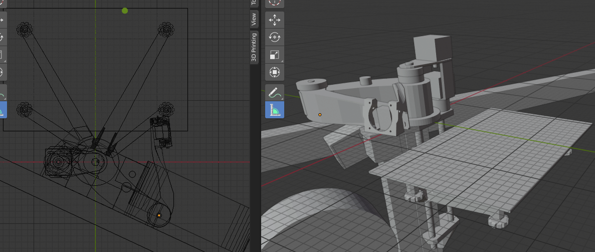
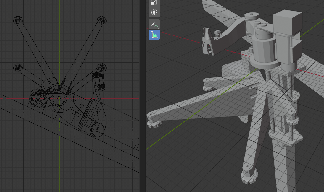
My SCARA design has 3 primary goals: Low cost, tall build volume (at least 800mm), and minimal space taken up by the printer (I have a very small space to work in, and probably shouldn't be building another printer to begin with). Accuracy doesn't have to be perfect for what I plan to make with it. The printer is designed to mount on a wall, and is based around a single SBR12 rail mounted to a 2x4, which acts as both Z guide and the axis for the shoulder joint, guaranteeing that the axes are parallel. And since the shoulder and elbow bearings are both in the same 3D printed part, those are guaranteed parallel as well. If I'm lucky, the Z ballscrew will double as the second constraint to prevent rotation of the bed around the rail. But if it's not perfectly straight then it will force the bed to rotate around the rail by a small amount as the screw turns, producing waves in the print.
I'm presently making a small prototype to see if the waves are acceptably small using cheap Chinese ballscrews. If so, I'll make a thread for discussion of this design. If not, I'll either abandon it and just print tall things in segments on my CR-10 and glue them together, or rework it to add a second rail. P-SCARA using two rails would be fun too, but I don't think it could be wall-mounted due to elbows hitting the wall. With the one-arm design I have the whole printer rotated 25 degrees, which makes the corner of the bed stick out farther into the room, but provides space for the elbow so the rest of the machine can be more flush with the wall. And if I can come up with a good hinge mechanism for the bed, it will be able to fold up into an extremely compact form when not in use.
I've attached some screenshots of the full size design, and a photo of the mini version in progress. The part dangling off the left side is where the extruder will be mounted, angled so the spool can be closer to the 2x4 and still have the filament come straight into the extruder. Ignore the black pole sticking up at the top; that's just a carbon fiber rod I'm currently using as the shaft for the elbow idler. Also I'm using a floating 10mm rod rather than SBR12 rail because I happened to have one lying around.
Probably because most people who have time to work on stuff have no money and thus have to see what's cheap and figure out how to make the best of it, while people who have money to buy optimal components have no time to build the darn thingQuote
pandaym
I agree that people tend to use too small hardware. It seems lots of people choose their hardware dimensions backwards, instead of configuring it according to what they want to do with it. It seems you thoroughly evaluated your linear rail setup, and it sounds like it is more than good enough. I think a lot of that comes from the fact that you used high quality rails, instead of the cheap stuff that is flooding the market now.
|
Re: Kinematic systems and linear guides July 10, 2020 12:50AM |
Registered: 11 years ago Posts: 5,780 |
Quote
pandaym
The changing bed tensions in corexy is also part of my concern. This I am sure will have a much bigger effect on setups with more play, so I think your setup is simply solid enough to tolerate it?
Being a mechanical engineer of course helps with some things. I do have various experience that has some sort of reference to what 3D printers do, and of course a general understanding of kinematics. That said, I am absolutely amazed by what hobbyists design and build, some of which is more advanced than I have ever done really. The thing is that for work, I have only ever had to do the machine elements, and electrical/automation engineers will then take over to add stuff like motors, sensors etc. Therefore I don’t have all that much experience in building complete systems, which would definitely have helped in this case. What I do have a lot of experience with is design optimization. So I know a lot about what to do for robust design, design for manufacturing and design for service. Apart from that I am experienced in analyzing designs for constrains, to compare the intended scheme to the actual and optimize. I guess this means I am better at taking something good and making it really good, than I am at designing from scratch. Also it is worth mentioning that a lot of what I know and how I think is based on theory, and when it gets put into practice, it often changes nature somewhat. So even though your corexy setup might not be ideal according to an initial analysis of the constrains, it still might end up being the ideal design after iterating the analysis with respect to practical properties. So all in all, I wouldn’t say I am more qualified to do an ideal printer design than non-engineers - but I will probably have a different approach.
As I said, I don't see anything in prints that I can attribute to dynamic belt tension behavior, but I'm not entirely sure what to look for. In such a situation, I try to imagine what a very large variation in dynamic tension would do and then scale it back to a more realistic level. I just don't see it in the prints. I used to be an electrical engineer before I became a dentist. My mechanical skills are limited, and I've long since forgotten most of the math needed to calculate things, so I'm more of a "if there's any doubt, make it bigger" type mechanical "engineer". I've seen a lot of crummy printers with 8 mm round rails that flop around if you look at them the wrong way, so I used a relatively large 8x24mm rail for the X axis. The Y axis rails happen to be the same size because I found a good deal on them. I used 9mm belts because they will stretch less than 6 mm belts. I stacked bearings for pulleys because the larger ball size means they'll last a lot longer than the tiny bearings in 3D printer pulleys.
I have access to a well equipped machine shop so I can do a lot of things that other people can't, but my shop skills are pretty limited so I try to do the minimum using mills and lathes. I use a lot of square and rectangular aluminum tubing, and cast tooling plate that really reduces the shop work required. I live in the rust belt so we have a lot of industrial surplus in the area. I buy t-slot and tubing at scrap yards for scrap price, and get tooling plate cut-offs for scrap price from a local metals supplier.
My printer has a belt lifted Z axis that uses a 30:1 worm gear reducer that prevents the bed from moving when motor power is cut. The bed is a piece of cast tooling plate on a Kelvin-type kinematic mount that lets it expand freely when it heats. There's no autoleveling or zeroing because it isn't needed. I don't have to adjust the bed unless I take the Z axis apart, and that's pretty rare.
Here's a recent 36 hour print- 564.5 mm tall. The Z axis can go to about 690 mm, but I have yet to print anything that tall.

Edited 1 time(s). Last edit at 07/11/2020 09:11AM by the_digital_dentist.
Ultra MegaMax Dominator 3D printer: [drmrehorst.blogspot.com]
|
Re: Kinematic systems and linear guides July 10, 2020 05:25AM |
Registered: 12 years ago Posts: 1,450 |
Sometimes the specification of the printer leads you inexorably to a particular kinematic. I was approached some months ago by somebody who wanted to 3D scan people to print full size for making lightweight armatures which would be used for making bespoke dummies for shops and other displays. The idea was to reinforce the armature with glass fiber rods and finish them off with about a 1mm layer of pasted paper or glass fiber. The unusual aspect of this was that they only had to be visually accurate - an inch or two of error is of little importance. After firming up the "inch or two" to 3mm per meter of inaccuracy I was led to the most likely candidate being a hangprinter.
Sadly the Coronavirus crisis and the likely financial doldrums mean that I will probably not hear any more of this project.
Mike
Sadly the Coronavirus crisis and the likely financial doldrums mean that I will probably not hear any more of this project.
Mike
|
Re: Kinematic systems and linear guides July 10, 2020 01:44PM |
Registered: 10 years ago Posts: 14,672 |
I have Cartesian, Delta, CoreXY and SCARA printers. My take:
- If you are on a tight budget, choose Cartesian and don't go large. Cartesian is more tolerant of mechanical inaccuracy and poor electronics/firmware than other architectures.
- Deltas are great for single extrusion, but need to be mechanically precise and have capable electronics and firmware. My go-to printer is the delta.
- CoreXY is good for multi extrusion and tool changing, but mechanically more complex and expensive than delta
- SCARA is great for really large build areas, but mechanical rigidity is problematic
Edited 1 time(s). Last edit at 07/10/2020 01:45PM by dc42.
Large delta printer [miscsolutions.wordpress.com], E3D tool changer, Robotdigg SCARA printer, Crane Quad and Ormerod
Disclosure: I design Duet electronics and work on RepRapFirmware, [duet3d.com].
|
Re: Kinematic systems and linear guides September 11, 2020 01:49PM |
Registered: 3 years ago Posts: 2 |
Regarding rails I would say that you can get good rails that dont cost a fortune. LDO makes some pretty good rails and leadscrews. I dont think 38 euros for a 400 mm MGN12H rail is expensive. The Railcore community is increasingly using both LDO steppers, rails and leadscrews.
Shop owner www.HighTemp3D.com We specialize in high temperature printers and printer parts.
Shop owner www.HighTemp3D.com We specialize in high temperature printers and printer parts.
Sorry, only registered users may post in this forum.