Sides for a box frame printer? Electronics location? And?
Posted by aamcle
|
Sides for a box frame printer? Electronics location? And? May 20, 2021 05:00PM |
Registered: 5 years ago Posts: 145 |
Hi.
I'm going to be wiring up the Cartesian printer I've been building for what seems to be forever..
My choices from positioning the electronics seem to be outside of the box on a side wall or in the base as there will be easy access to them if the bed is at the top.
My other question is what to use for the side panels and door? Polycarbonate seems like a good choice or even 6mm plywood as I can get the ply with a flame retarded treatment.
The others tricky thing is constructing a "top" I'm far from sure what the easiest way to do that would be.
If you have any thoughts you would like to share I'd appreciate it.
Thanks All. Aamcle
|
Re: Sides for a box frame printer? Electronics location? And? May 20, 2021 09:00PM |
Registered: 3 years ago Posts: 55 |
|
Re: Sides for a box frame printer? Electronics location? And? May 20, 2021 10:57PM |
Registered: 11 years ago Posts: 5,780 |
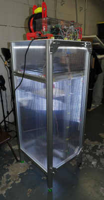
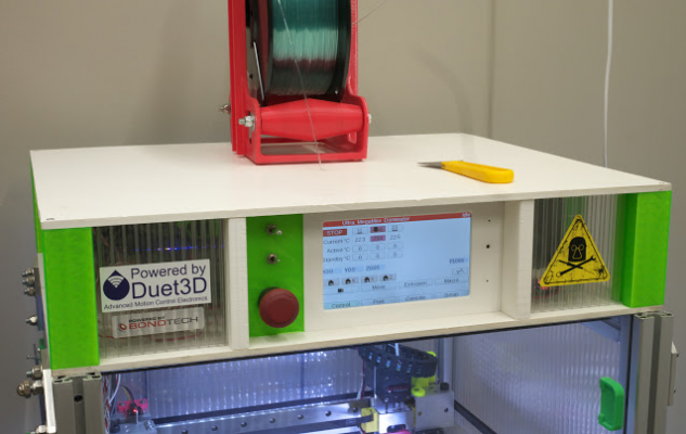
I like double walled PC for the sides- in my printer it fits inside the t-slots in the frame (with old electronics):
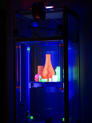
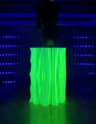
It has some nice optical properties as well as being a good thermal insulator:
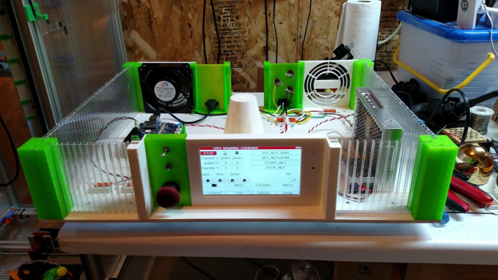
I like the electronics on top- I can access them without bending over whether the machine is running or not.
Ultra MegaMax Dominator 3D printer: [drmrehorst.blogspot.com]
It has some nice optical properties as well as being a good thermal insulator:
I like the electronics on top- I can access them without bending over whether the machine is running or not.
Ultra MegaMax Dominator 3D printer: [drmrehorst.blogspot.com]
|
Re: Sides for a box frame printer? Electronics location? And? May 21, 2021 03:31AM |
Registered: 5 years ago Posts: 145 |
The twin wall gives a interesting effect but does it do anything for the rigidity of the printer?
I do like the electronics on top it's not something that occurred to me, is your printer direct drive or have you managed to fit a Bowden tube in there?
My printer has a build volume of 300*300*400mm the frame is 3030, with 2*Z axis, a glass plate on the bed and a simple Cartesian layout. It should be stable and accurate but not fast.
Atb. Aamcle
Edited 1 time(s). Last edit at 05/21/2021 03:46AM by aamcle.
|
Re: Sides for a box frame printer? Electronics location? And? May 21, 2021 06:47AM |
Registered: 11 years ago Posts: 5,780 |
No, the dual layer PC doesn't do anything to stiffen the frame, but the frame is pretty rigid (4040 t-slot). Direct drive extruder.
Most of the electrical connections to the mechanism are at the top of the printer, so putting electronics there helps keep cables short. My original plan was to make the electronics and XY stage as a module that could be dropped onto different size Z axes/frames. Putting electronics on top would make sense for that...
Ultra MegaMax Dominator 3D printer: [drmrehorst.blogspot.com]
|
Re: Sides for a box frame printer? Electronics location? And? May 22, 2021 04:58AM |
Registered: 5 years ago Posts: 145 |
Thanks for replying 
I'm not sure that 3030 will be enough without boxing in the printer but looking at a lot of of commercial products it probably is.
On a frame that's 460*460*600mm putting the controls on top does make good sense I'm tempted but I have a boden hotend. Fortunately I designed the carriage to be compatible with the Prussia system so I can swap easily.
May I ask how you have stopped the connections to the hotend "sagging" and snagging it?I
Looking at the pictures more carefully it appears that there is quite a lot of height above the XY axis, is that how you did it?
One thing I still haven't got to the bottom of is maintaining a constant ambient temperature in an enclosed printer.
My build plate is apparently capable of 300W that's a lot of heat in a small enclosed chamber. Even when the print is underway and the bed is just maintaining a temperature I would expect the temperature in the chamber to climb.
The obvious solution is to use a temperature probe and a fan and or a vent to let the heat out. So far so good but doing that must inevitably lead to drafts am I being over sensitive , is it really a problem?I
Atb. Aamcle
Edited 1 time(s). Last edit at 05/22/2021 05:02AM by aamcle.
|
Re: Sides for a box frame printer? Electronics location? And? May 22, 2021 10:35AM |
Registered: 11 years ago Posts: 5,780 |
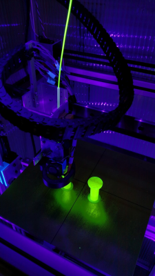
I run wiring to the hot-end inside a horizontal drag chain that makes a large loop so that the wires don't have to bend sharply anywhere. Some commercial printers do similar and include filament feed tubes inside the drag chain. The particular drag chain I used sags quite a bit, but works OK so I haven't bothered to swap it out. Unfortunately there's no spec for that type of behavior, so you just have to buy the drag chain and hope it works OK. One thing I'm still not happy with is the connections between the extruder carriage and the wires in the drag chain. I used a bunch of separate connectors and though it works reliably, it's a bit sloppy looking. Some day I'll redesign the carriage to have a circuit board with a single connector for all the wiring. What I don't think I'll ever do is make a set of pretty covers to cover up all the wiring to the extruder carriage that I see in so many printers, both commercial and hobbyist built. I like to be able to see the connections and to access the hot-end easily, without having to remove a bunch of parts that I'll have to put back later.
I used a bunch of Wago 5 position lever nuts to make connections inside the electronics enclosure. IRIC, I hot melt glued them down. They are absolutely reliable and don't require tools to make connections or to remove wires. I set up buses for +24V, ground, 117VAC line and neutral, and for powering LEDs with buck converters.
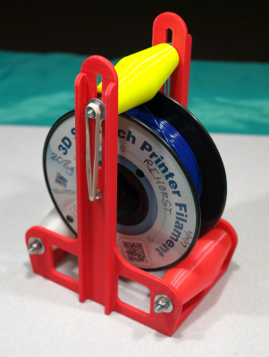
I like direct drive extrusion because I like to print flexible filament, so I designed the printer so the spool sits on top and feeds filament straight down through the electronics enclosure to the extruder. The vertical space above the XY carriage ensures that, even at the corners of the bed, the filament will feed easily. The hole that the filament feeds through is located over the center of the print bed which is where prints are normally made. If I had been really smart about it, I would have made a spool holder platform attached to the bottom of the electronics enclosure and then cut the top panel to fit around it so that I could take the cover off during a print without having to move the spool holder first. Maybe I'll modify it some day. The straight down filament path, without the friction of any tubing, minimizes any potential print artifacts that could come from filament tube friction or pulling at the extruder carriage. The spool holder itself has ball bearings in the rollers that keep the filament from springing off the spool and tying itself into knots.
I used 1/4" foamed PVC board for the top and bottom of the electronics enclosure. It has pretty good thermal properties, but it sags a bit so the bottom piece (which is the top of the print chamber) has some aluminum tube reinforcing it. The filament feeds through a printed cone that supports the center of the top cover. The PVC board is very soft stuff and easily damaged when transporting the machine, so I have to be a little bit careful with it. You can see in the picture that there is a 5" fan in the back left, right in front of the Duet board, and a large vent on the back right side of the enclosure, closer to the power supply. The fan is a 220VAC unit that I power with 117VAC when the machine is turned on. It is very quiet and moves sufficient air to keep things from getting warm in the enclosure. I use another 220VAC fan at 117V to blow air across the chamber heater - it keeps the heater from getting too hot but doesn't stir the air up enough to cause a problem for the prints.
I don't know what you're planning to print, but 300W for a 460 x 460 bed plate seems a bit low. You'll be waiting for it to heat up ... This site calculates the heat-up time based on bed construction and heater power/size. It seems pretty accurate. I wouldn't use a heater that's smaller than the bed plate because the unheated edges of the plate will be quite a bit cooler than the center portion tat is heated. The result is warping. You'll need some bed flatness compensation to fix that.
My printer enclosure isn't perfectly insulated, and the 750W bed heater doesn't get it very warm by itself. That's because the bed gets set to relatively low temperatures and it would take forever to heat the enclosure with the bed set to say 100C for printing ABS. I use a 500W heater for the chamber and it takes about 20 minutes to get the enclosure up to 50C for ABS printing. I normally start the chamber heater when I start the print and the chamber gets to 50C before the print would start having problems.
Edited 2 time(s). Last edit at 05/22/2021 10:44AM by the_digital_dentist.
Ultra MegaMax Dominator 3D printer: [drmrehorst.blogspot.com]
|
Re: Sides for a box frame printer? Electronics location? And? May 23, 2021 06:40AM |
Registered: 5 years ago Posts: 145 |
Sorry, only registered users may post in this forum.

