Help configuring firmware of printer with dual direct extruder
Posted by feynman137
|
Help configuring firmware of printer with dual direct extruder August 26, 2021 11:20PM |
Registered: 2 years ago Posts: 13 |
I have a core-xy that I've been trying to configure using rep rap and a duet mainboard 6hc and expansion board 3hc. I have made some progress configuring the code thus far, thanks to help from the rep rap and duet communities. Right now all of the limit switches, steppers, and dimensions are working great. So no problem homing the printer, but I haven't made any progress on the hot-end. Can someone help me build the G code for the hardware and connections described below? I have gotten started using the config tool, but I can't use this for a dual extruder head.
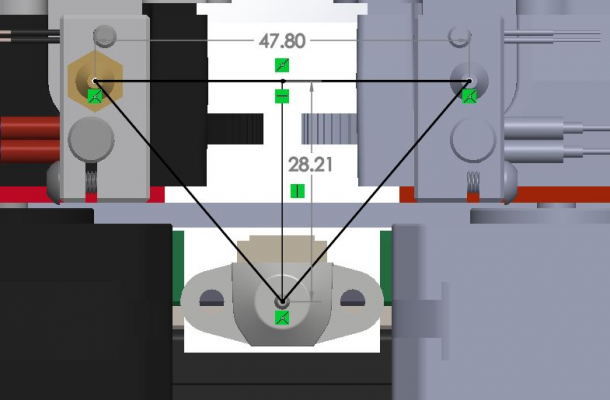
The picture attached is the dimensions of the print head. Below are the connections:
Primary extruder heater --> expansion board out1
Primary extruder thermistor --> expansion board temp1
Primary extruder fan --> expansion board out 7
Primary extruder --> expansion board driver1
Secondary extruder heater --> expansion board out2
Secondary extruder thermistor --> expansion board temp2
Secondary extruder fan --> expansion board out 8
Secondary extruder --> expansion board driver2
I am confident in my driver codes except the extruder drives. Limit switch and Z probe codes are configured as well. But everything regarding the hot-end is going to be off.
; Configuration file for Duet 3 (firmware version 3)
; executed by the firmware on start-up
;
; generated by RepRapFirmware Configuration Tool v3.2.3 on Wed Jun 23 2021 23:47:21 GMT-0400 (Eastern Daylight Time)

; General preferences
G90                                             ; send absolute coordinates...
M83                                             ; ...but relative extruder moves
M550 P"Duet 3"                                  ; set printer name
M669 K1                                         ; select CoreXY mode

; Drives
M569 P0.0 S1                                    ; physical drive 0.0 goes forwards
M569 P0.1 S1                                    ; physical drive 0.1 goes forwards
M569 P0.2 S1									; physical drive 0.2 goes forwards
M569 P0.3 S1									; physical drive 0.3 goes forwards
M569 P0.4 S1									; physical drive 0.4 goes forwards
M569 P0.5 S1									; physical drive 0.5 goes forwards
M569 P1.1 S1                                    ; physical drive 1.1 goes forwards
M569 P1.2 S1                                    ; physical drive 1.2 goes forwards
M584 X0.0 Y0.1 Z0.2:0.3:0.4:0.5 E1.1:1.2        ; set drive mapping
M350 X16 Y16 Z16 E16:16 I1                      ; configure microstepping with interpolation
M92 X40.00 Y40.00 Z400.00 E420.00:420.00        ; set steps per mm
M566 X900.00 Y900.00 Z60.00 E120.00:120.00      ; set maximum instantaneous speed changes (mm/min)
M203 X6000.00 Y6000.00 Z120.00 E1200.00:1200.00 ; set maximum speeds (mm/min)
M201 X500.00 Y500.00 Z10.00 E250.00:250.00      ; set accelerations (mm/s^2)
M906 X1500 Y1500 Z1500 E800:800 I30             ; set motor currents (mA) and motor idle factor in per cent
M84 S30                                         ; Set idle timeout

; Axis Limits
M208 X0 Y0 Z0 S1                              ; set axis minima
M208 X600 Y540 Z496 S0                          ; set axis maxima

; Endstops
M574 X1 S1 P"!io4.in"                           ; configure active-low endstop for low end on X via pin !io1.in
M574 Y1 S1 P"!io5.in"                           ; configure active-low endstop for low end on Y via pin !io5.in
M574 Z2 S1 P"!io3.in"                           ; configure active-low endstop for low end on Z via pin !io3.in

; Z-Probe
M950 S0 C"io7.out"                              ; create servo pin 0 for BLTouch
M558 P9 C"^io7.in" H7 F120 T6000                ; set Z probe type to bltouch and the dive height + speeds
G31 P500 X0 Y0 Z1.67                            ; set Z probe trigger value, offset and trigger height
M557 X10:600 Y10:540 S100                        ; define mesh grid

; Heaters
M308 S0 P"temp1" Y"thermistor" T100000 B4138    ; configure sensor 0 as thermistor on pin temp1
M950 H0 C"out1" T0                              ; create nozzle heater output on out1 and map it to sensor 0
M307 H0 B0 S1.00                                ; disable bang-bang mode for heater  and set PWM limit
M143 H0 S280                                    ; set temperature limit for heater 0 to 280C
M308 S1 P"temp2" Y"thermistor" T100000 B4138    ; configure sensor 1 as thermistor on pin temp2
M950 H1 C"out2" T1                              ; create nozzle heater output on out2 and map it to sensor 1
M307 H1 B0 S1.00                                ; disable bang-bang mode for heater  and set PWM limit
M143 H1 S280                                    ; set temperature limit for heater 1 to 280C

; Fans
M950 F0 C"out7" Q500                            ; create fan 0 on pin out7 and set its frequency
M106 P0 S1 H-1                                  ; set fan 0 value. Thermostatic control is turned off
M950 F1 C"out8" Q500                            ; create fan 1 on pin out8 and set its frequency
M106 P1 S1 H-1                                  ; set fan 1 value. Thermostatic control is turned off

; Tools
M563 P0 D0 H1 F0                                ; define tool 0
G10 P0 X0 Y0 Z0                                 ; set tool 0 axis offsets
G10 P0 R0 S0                                    ; set initial tool 0 active and standby temperatures to 0C

; Custom settings are not defined

; Miscellaneous
M575 P1 S1 B57600                               ; enable support for PanelDue
|
Re: Help configuring firmware of printer with dual direct extruder August 30, 2021 06:27PM |
Registered: 2 years ago Posts: 13 |
After doing research and getting some help. The code below is what I am using:
; Configuration file for Duet 3 (firmware version 3)
; executed by the firmware on start-up
;
; generated by RepRapFirmware Configuration Tool v3.2.3 on Wed Jun 23 2021 23:47:21 GMT-0400 (Eastern Daylight Time)

; General preferences
G90                                             ; send absolute coordinates...
M83                                             ; ...but relative extruder moves
M550 P"Duet 3"                                  ; set printer name
M669 K1                                         ; select CoreXY mode

; Drives
M569 P0.0 S1                                    ; physical drive 0.0 goes forwards
M569 P0.1 S1                                    ; physical drive 0.1 goes forwards
M569 P0.2 S1									; physical drive 0.2 goes forwards
M569 P0.3 S1									; physical drive 0.3 goes forwards
M569 P0.4 S1									; physical drive 0.4 goes forwards
M569 P0.5 S1									; physical drive 0.5 goes forwards
M569 P1.1 S1                                    ; physical drive 1.1 goes forwards
M569 P1.2 S1                                    ; physical drive 1.2 goes forwards
M584 X0.0 Y0.1 Z0.2:0.3:0.4:0.5 E1.1:1.2        ; set drive mapping
M350 X16 Y16 Z16 E16:16 I1                      ; configure microstepping with interpolation
M92 X40.00 Y40.00 Z400.00 E420.00:420.00        ; set steps per mm
M566 X900.00 Y900.00 Z60.00 E120.00:120.00      ; set maximum instantaneous speed changes (mm/min)
M203 X6000.00 Y6000.00 Z120.00 E1200.00:1200.00 ; set maximum speeds (mm/min)
M201 X500.00 Y500.00 Z10.00 E250.00:250.00      ; set accelerations (mm/s^2)
M906 X1500 Y1500 Z1500 E800:800 I30             ; set motor currents (mA) and motor idle factor in per cent
M84 S30                                         ; Set idle timeout

; Axis Limits
M208 X0 Y0 Z0 S1                              ; set axis minima
M208 X600 Y540 Z496 S0                          ; set axis maxima

; Endstops
M574 X1 S1 P"!io4.in"                           ; configure active-low endstop for low end on X via pin !io1.in
M574 Y1 S1 P"!io5.in"                           ; configure active-low endstop for low end on Y via pin !io5.in
M574 Z2 S1 P"!io3.in"                           ; configure active-low endstop for low end on Z via pin !io3.in

; Z-Probe
M950 S0 C"io7.out"                              ; create servo pin 0 for BLTouch
M558 P9 C"^io7.in" H7 F120 T6000                ; set Z probe type to bltouch and the dive height + speeds
G31 P500 X0 Y0 Z1.67                            ; set Z probe trigger value, offset and trigger height
M557 X10:600 Y10:540 S100                        ; define mesh grid

; Heaters

M308 S0 P"1.temp0" Y"thermistor" T100000 B4138  ; configure sensor 0 as thermistor on expansion board pin 1.temp0
M950 H0 C"1.out0" T0                            ; create nozzle heater output on 1.out0 and map it to sensor 0
M307 H0 B0 S1.00                                ; disable bang-bang mode for heater  and set PWM limit
M143 H0 S280                                    ; set temperature limit for heater 0 to 280C
M308 S1 P"1.temp1" Y"thermistor" T100000 B4138  ; configure sensor 2 as thermistor on expansion board pin 1.temp1
M950 H1 C"1.out1" T1                            ; create nozzle heater output on 1.out2 and map it to sensor 1
M307 H1 B0 S1.00                                ; disable bang-bang mode for heater  and set PWM limit
M143 H1 S280                                    ; set temperature limit for heater 1 to 280C

; bed heater0
M308 S2 P"0.temp0" Y"thermistor" T100000 B4138    ; configure sensor 2 as thermistor on mainboard pin temp0
M950 H2 C"0.out9" T2                            ; create bed heater output on 1.out0 and map it to sensor 2
M140 P0 H2                                         ;assign H2 to bed heater0
M307 H2 B0 S10.00                                ; disable bang-bang mode for the bed heater and set PWM limit
M143 H2 S120                                     ;set temperature limit for heater 0 to 120C

; bed heater1
M308 S3 P"0.temp1" Y"thermistor" T100000 B4138    ; configure sensor 3 as thermistor on mainboard pin temp1
M950 H3 C"0.out6" T3                             ; create bed heater output on 1.out0 and map it to sensor 3
M140 P1 H3                                         ;assign H2 to bed heater0
M307 H3 B0 S10.00                                ; disable bang-bang mode for the bed heater and set PWM limit
M143 H3 S120                                     ;set temperature limit for heater 0 to 120C

; bed heater2
M308 S4 P"0.temp2" Y"thermistor" T100000 B4138    ; configure sensor 4 as thermistor on mainboard pin temp2
M950 H4 C"0.out5" T4                             ; create bed heater output on 1.out0 and map it to sensor 4
M140 P2 H4                                          ;assign H2 to bed heater0
M307 H4 B0 S10.00                                ; disable bang-bang mode for the bed heater and set PWM limit
M143 H4 S120                                     ;set temperature limit for heater 0 to 120C

; bed heater3
M308 S5 P"0.temp3" Y"thermistor" T100000 B4138    ; configure sensor 5 as thermistor on mainboard pin temp3
M950 H5 C"0.out4" T5                             ; create bed heater output on 1.out0 and map it to sensor 5
M140 P3 H5                                      ;assign H2 to bed heater0
M307 H5 B0 S10.00                                ; disable bang-bang mode for the bed heater and set PWM limit
M143 H5 S120                                     ;set temperature limit for heater 0 to 120C


; Fans
M950 F0 C"1.out7" Q500                          ; create fan 0 on pin 1.out7 and set its frequency
M106 P0 S0 H-1                                  ; set fan 0 value. Thermostatic control is turned off
M950 F1 C"1.out8" Q500                          ; create fan 1 on pin 1.out8 and set its frequency
M106 P1 S1 H-1                                  ; set fan 1 value. Thermostatic control is turned off

; Tools
M563 P0 D0 H0 F0                                ; define tool 0
G10 P0 X23.9 Y-28.21 Z0                          ; set tool 0 axis offsets
G10 P0 R0 S0                                    ; set initial tool 0 active and standby temperatures to 0C
M563 P1 D1 H1 F1                                ; define tool 1
G10 P1 X-23.9 Y-28.21 Z0                         ; set tool 1 axis offsets
G10 P1 R0 S0                                    ; set initial tool 0 active and standby temperatures to 0C

; Custom settings are not defined

; Miscellaneous
M575 P1 S1 B57600                               ; enable support for PanelDue
Sorry, only registered users may post in this forum.