here is a possible solution maybe?
here is the melzi pinout [
www.geeetech.com]
i'm not sure what +ve or -ve are unless you are just talking about fan positive and fan negative pins.
is it ok for fan to be on all the time on the laser? (usually it is on all the time)
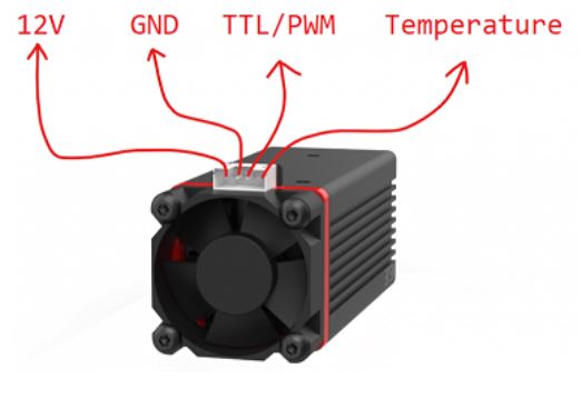
if the goal is to use the melzi board fan output as a logic control for laser TTL input:
if you need to invert fan pin then put a load across pins. (200ohm to 1k ) resistor across the fan terminals, this allows it to pull up/down depending on design. then use additional 1k resistor across output to TTL thru a voltage divider network or voltage level shifter board to reduce voltage output to 5v for TTL. it should work with low current to input.
as for pwm pin on the laser it is TTL input so it can run on low current 5v. so if you needed to you could add external logic.
i do not know the melzi board that well but you could compare it to the ramps laser setup which uses d9 (second fan output)
[
jtechphotonics.com]
and see if a similar pin is available on the board. both the ramps and the melzi use ATMEGA1284P chipset as far as i can tell. you might want to double check that part as well. i did not see additional PWM pins with output terminals on melzi at first glance. you could read up on chip schematics and solder to the direct pins on chip that are not used on melzi board.
i do not see where d9 is used on melzi. you might need to modify the pin d9 (which is a different physical pin) to get the job done. as far as i know the ttl signal spec is to 5v, so going over 5v might damage laser.