Minor Prusa modification
Posted by mikey
|
Re: Minor Prusa modification August 27, 2011 12:17PM |
Registered: 13 years ago Posts: 228 |
|
Re: Minor Prusa modification August 27, 2011 01:02PM |
Registered: 12 years ago Posts: 50 |
The 2 Z rods are extremely parallel.
+- a half mil at most.
The nylon bushings have more play in them then that so binding is not an issue.
in fact it bound up worse with one smooth rod on both sides.
And rocked back and forth a few mms.
Having 2 has made my Z super stable with a total rocking motion of .5mm
It also opens up the idea of moving Z motors to bottom,
and moving the side braces of the whole prusa out and increase the build surface.
In my opinion it was well worth it.
Its just a hack now with plexiglass and zipties
NOw that im finally printing, and with some decent quality im going to design some mounts.\
This shit is ridiculous though,
IMO more addictive then crack lol
Happy Hacking and printing
-Erik
|
Re: Minor Prusa modification August 27, 2011 02:53PM |
Registered: 12 years ago Posts: 26 |
I pay my bills as a controls engineer and PLC programmer. I used to work in machine design for an industrial cooking equipment supplier. Every day was a struggle to improve within the bounds of what was financially reasonable. I see what is going on in the improvements of the machine as a similar evolution of steady improvements on design deficiencies and real world tests to determine feasibility.
|
Re: Minor Prusa modification August 27, 2011 03:59PM |
Registered: 13 years ago Posts: 228 |
mikey Wrote:
-------------------------------------------------------
> I see what is
> going on in the improvements of the machine as a
> similar evolution of steady improvements on design
> deficiencies and real world tests to determine
> feasibility.
Certainly, and the more you dig into the wiki the more you can appreciate the long way. With an emphasis on biomimetics of course, and, as Erik pointed out, strongly addictive aspects.
But (I suppose) in other industrial settings there are minimal specs you are supposed to meet: the minimum your machine is supposed to be able to do is known, and used as a reference.
Maybe we are missing that aspect : what are the minimal specs a machine needs to meet to be called, for example a Mendel? Not about self-reproductivity (IMHO a non-issue as long as we have to keep injecting purchased metal at each generation to compensate "analogic losses") , but about, for example, the tolerances of what we are able to make: are we OK if our pieces come out at plus or minus 1mm? or 0.1 mm? or half that value? Some practical uses of our plastic thingies strongly depend on those specs too.
Second example: what would be the acceptable vibration reference values for our machines frames, a proxy for stiffness/dampening? (mental note: we can do FFT analysis on recordings of machines frame noise up to 10 KHz and it said to be a valid tool for evaluation. Alternative: accelerometry, also within reach)...
etc.
One or several sets of reference values, built on consensus, could help makers, sellers and developers meet on a common ground.
It seems to me there might have been (moderate) attempts of that in the past (?)
|
Re: Minor Prusa modification August 29, 2011 10:59AM |
Registered: 12 years ago Posts: 26 |
|
Re: Minor Prusa modification August 29, 2011 12:37PM |
Registered: 13 years ago Posts: 485 |
|
Re: Minor Prusa modification August 29, 2011 02:47PM |
Registered: 12 years ago Posts: 50 |
Im going to work on the whole standards thing here.
I like the prusa i have now but there are too many places that can be improved on.
If i were to make every change i wanted, i would have to rebuild her anyways.
Im thinking up some different designs and ideas to make it as rigid and isolated as i can.
Study enough to print something out.
swap out the extruder with a router and route a PCB
and have tolerances that are much tighter.
as i proceed further i will let you all know my progress.
-E
|
Re: Minor Prusa modification August 29, 2011 05:57PM |
Admin Registered: 17 years ago Posts: 7,879 |
Quote
Have you thought about using a closed box instead of an open one?
Yes if you want to print ABS build a box around the base and omit the two bracing pieces. The box has to be a lot taller than the Z axis to allow the filament to enter via a small hole in the middle without bending too sharply when the X axis moves. The design I show above is equivalent to the Mendel or Prusa, which can print PLA without a box, but this design is easier to box as you get one face for free.
I don't think a belt driven machine will make a good router. Belt isn't stiff enough. You need ball screws for milling, but then they are not fast enough for FFF. A machine that does both milling and FFF will always be compromised and not particularly good at at either.
[www.hydraraptor.blogspot.com]
|
Re: Minor Prusa modification August 30, 2011 03:24AM |
Registered: 13 years ago Posts: 228 |
Same comment on routing: ppl have milled pcbs on mendels and darwins and makerbots, but have a close look at the pictures, the results are not very... accurate. The vibration issue reveals itself there.
Issues emerge from the belts, but also from the shaft play in dremels & co. (proxxon is said to have less play)
side note: I'd love to see more development of skeinforge's milling capabilities. There are very few open source toolpath generators really operational.
I started drafting something along Nophead's idea, but with 12 mm smooth bars.
The beauty of his design is that it can easily adapted either for very simple cuts (possible to buy MDF pre-cut), or for a more elaborated routed design.
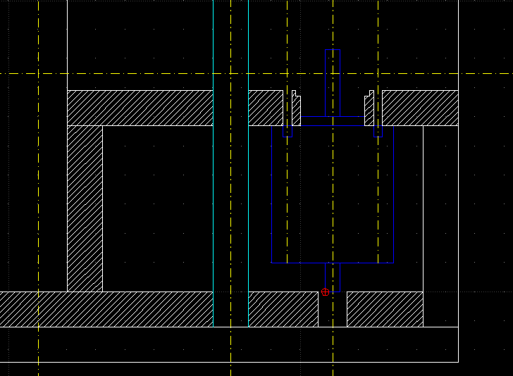
Possible improvements: The Z axes and motors are held in the air by cantilevered pieces. This solution is very straightforward, but vibration-prone. In my routed version I intend to anchor the Z smooth bars ends into the base plate. The mount has a box design for increased rigidity.
I'd lile to double the vertical plates to pour some epoxy-sand in the middle. We'll see.
I'll have to stop designing for the next couple of months tough. Duh.
Edited 1 time(s). Last edit at 08/30/2011 03:26AM by Lanthan.
Issues emerge from the belts, but also from the shaft play in dremels & co. (proxxon is said to have less play)
side note: I'd love to see more development of skeinforge's milling capabilities. There are very few open source toolpath generators really operational.
I started drafting something along Nophead's idea, but with 12 mm smooth bars.
The beauty of his design is that it can easily adapted either for very simple cuts (possible to buy MDF pre-cut), or for a more elaborated routed design.
Possible improvements: The Z axes and motors are held in the air by cantilevered pieces. This solution is very straightforward, but vibration-prone. In my routed version I intend to anchor the Z smooth bars ends into the base plate. The mount has a box design for increased rigidity.

I'd lile to double the vertical plates to pour some epoxy-sand in the middle. We'll see.
I'll have to stop designing for the next couple of months tough. Duh.
Edited 1 time(s). Last edit at 08/30/2011 03:26AM by Lanthan.
|
Re: Minor Prusa modification August 30, 2011 04:57AM |
Admin Registered: 17 years ago Posts: 7,879 |
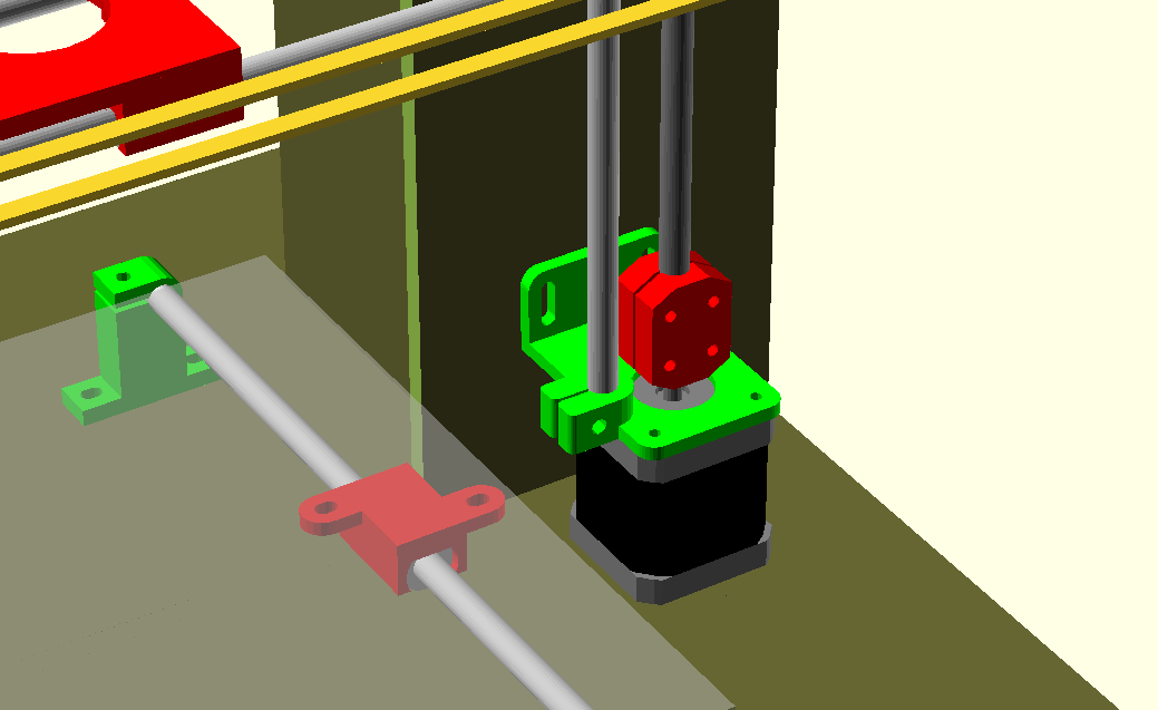
My z-motors are not held in the air. They rest on the base and are simply anchored to the back by the brackets to stop them moving laterally.
[www.hydraraptor.blogspot.com]
[www.hydraraptor.blogspot.com]
|
Re: Minor Prusa modification August 30, 2011 06:58AM |
Registered: 13 years ago Posts: 228 |
|
Re: Minor Prusa modification August 30, 2011 07:59AM |
Admin Registered: 17 years ago Posts: 7,879 |
The bars go though the clamp in the motor bracket and rest on the top of the motor, but they don't bear any vertical force anyway. The weight of the X axis is supported by the motor and the coupling.
[www.hydraraptor.blogspot.com]
[www.hydraraptor.blogspot.com]
|
Re: Minor Prusa modification August 30, 2011 10:10AM |
Registered: 13 years ago Posts: 228 |
|
Re: Minor Prusa modification August 30, 2011 02:38PM |
Admin Registered: 17 years ago Posts: 7,879 |
It is half the motor width, i.e. 21.5mm. I chose that because the bracket is the same size as the motor and the clamp has a rigid half inboard the bracket to give accurate positioning and the other half is a slightly flexible band that clamps the bar using a captive nut. That makes the centre of the rod line up roughly with the edge of the motor.
Edited 3 time(s). Last edit at 08/30/2011 02:44PM by nophead.
[www.hydraraptor.blogspot.com]

Edited 3 time(s). Last edit at 08/30/2011 02:44PM by nophead.
[www.hydraraptor.blogspot.com]
|
Re: Minor Prusa modification August 31, 2011 04:22AM |
Registered: 13 years ago Posts: 228 |
Very clever and economic, almost Zen.
My concern would be with transmitting the motors vibration to the smooth rod and the frame and thus amplifying it .
I adopt basic isolation and dampening measures nearest of the vibration sources each time it is possible. I tend to slip a cork (or similar) gasket in the contact area between the motors and the mounts.
Not clear to me if this would be possible here. You'd need two dampeners:
- one between the motor and the bottom plate
- one between the motor and the upper assembly plus rod
|
Re: Minor Prusa modification August 31, 2011 05:22AM |
Admin Registered: 17 years ago Posts: 7,879 |
I must admit noise is of little concern to me compared to functionality. I wouldn't put soft material under the motors as its thickness would be included in the Z calibration. I imagine cork expands with atmospheric moisture.
My Prusa is almost silent and my other machines with MDF boxes around them are a lot nosier but they work better,
[www.hydraraptor.blogspot.com]
My Prusa is almost silent and my other machines with MDF boxes around them are a lot nosier but they work better,
[www.hydraraptor.blogspot.com]
|
Re: Minor Prusa modification August 31, 2011 07:38AM |
Registered: 13 years ago Posts: 228 |
Acoustic noise's not the problem but vibration amplified up to the the extruder tip and the spring-mounted build surface is.
Yes, soft/absorbing material must be constrained, and the reference must be provided by a hard surface.
And of course... for all usual plastic melting purposes, the Z axis is almost never active while the extruder is printing. Its contribution to "noise" is minimal.
So better to concentrate on X and Y motors isolation.
|
Re: Minor Prusa modification August 31, 2011 08:22AM |
Admin Registered: 17 years ago Posts: 7,879 |
I don't think high frequency vibrations have any effect on extrusion, the viscous plastic acts as a low pass filter. Motor vibrations are at micro step rate, during which time only microns of plastic are dispensed.
In fact even quite obvious overshoot / ringing in the movement of the bed caused by the springiness of the motor and belt combo don't seem to have any noticeable effect on the filament path. I don't see any rippling at corners, etc. I expect I would if I increased my outline speed though.
I don't don't think spring mounted build surfaces are good for quality. I prefer a rigid mount and leave the Z axis nut traps open at the bottom so the nozzle cannot be driven into the bed with much force.
[www.hydraraptor.blogspot.com]
|
Re: Minor Prusa modification September 15, 2011 01:23PM |
Registered: 13 years ago Posts: 632 |
@ Nophead's new machine : Looks nice. I wonder if maybe you put the vertical MDF braces on the outer edge and facing the other way you could make it "easy" to detach the vertical assembly from the base, and place it face down on the base making a self contained box for traveling.
Edited 1 time(s). Last edit at 09/15/2011 01:25PM by bryanandaimee.
Edited 1 time(s). Last edit at 09/15/2011 01:25PM by bryanandaimee.
|
Re: Minor Prusa modification September 15, 2011 02:16PM |
Admin Registered: 17 years ago Posts: 7,879 |
It could certainly be put together that way. The only change would be to make the base wider by the thickness of the braces. It would make it a bit harder to get at things though and I was planning to mount the electronics behind.
[www.hydraraptor.blogspot.com]
[www.hydraraptor.blogspot.com]
|
Re: Minor Prusa modification September 16, 2011 04:13PM |
Admin Registered: 17 years ago Posts: 7,879 |
Thinking about it further the Z-axis won't lie flat on the base because one of the Y bars goes all the way to the back edge. If the braces were left where they are and made just a little wider than the Y bar clamps are tall, then it would allow the z-axis to lie flat over the top of them for travelling.
[www.hydraraptor.blogspot.com]
[www.hydraraptor.blogspot.com]
|
Re: Minor Prusa modification December 01, 2011 02:17PM |

Sorry, only registered users may post in this forum.