|
Prusa i3 Pb calibration Z August 29, 2016 08:38AM |
Registered: 7 years ago Posts: 24 |
Bonjour à tous,
J'ai récemment acquis d'occasion une Prusa i3 Rework 1.0, firmware Marlin sous Repetier avec carte Arduino Mega 2560 et Ramps 1.4, HeatBed MK3 et pour le moment juste une alim 12V de PC qui délivre 250W env.
Le montage mécanique s'est déroulé pratiquement sans accroc, juste une tête JHead MKV de bousillée (ventilateur positionné dans le mauvais sens soufflant vers l'ext)...et oui on apprends de ses erreurs
Achat donc d'un Extrudeur Hexagon 1,75mm/0,4mm
Par contre depuis plusieurs jours j'essaie de calibrer l'imprimante sans réel succès.
J'ai avant toute chose réalisé une calibration de mon Extrudeur avec du PLA.
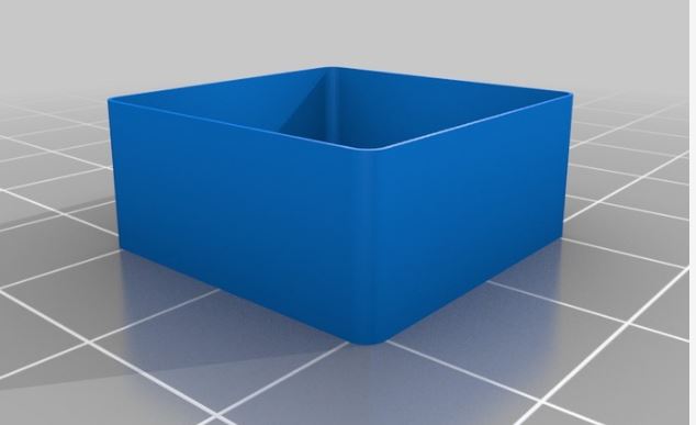
Ensuite j'ai tenté l'impression du cube (layer height) 0,5 mm ci-après [www.thingiverse.com] avec les paramètres suivants :
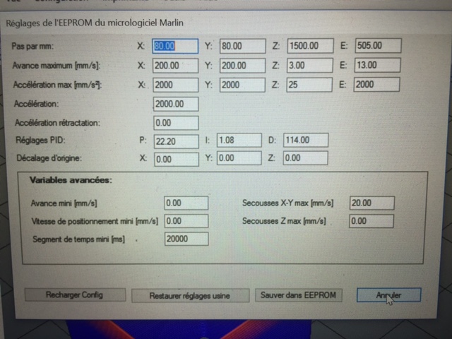
X=80 Y=80 Z=1500 E=500
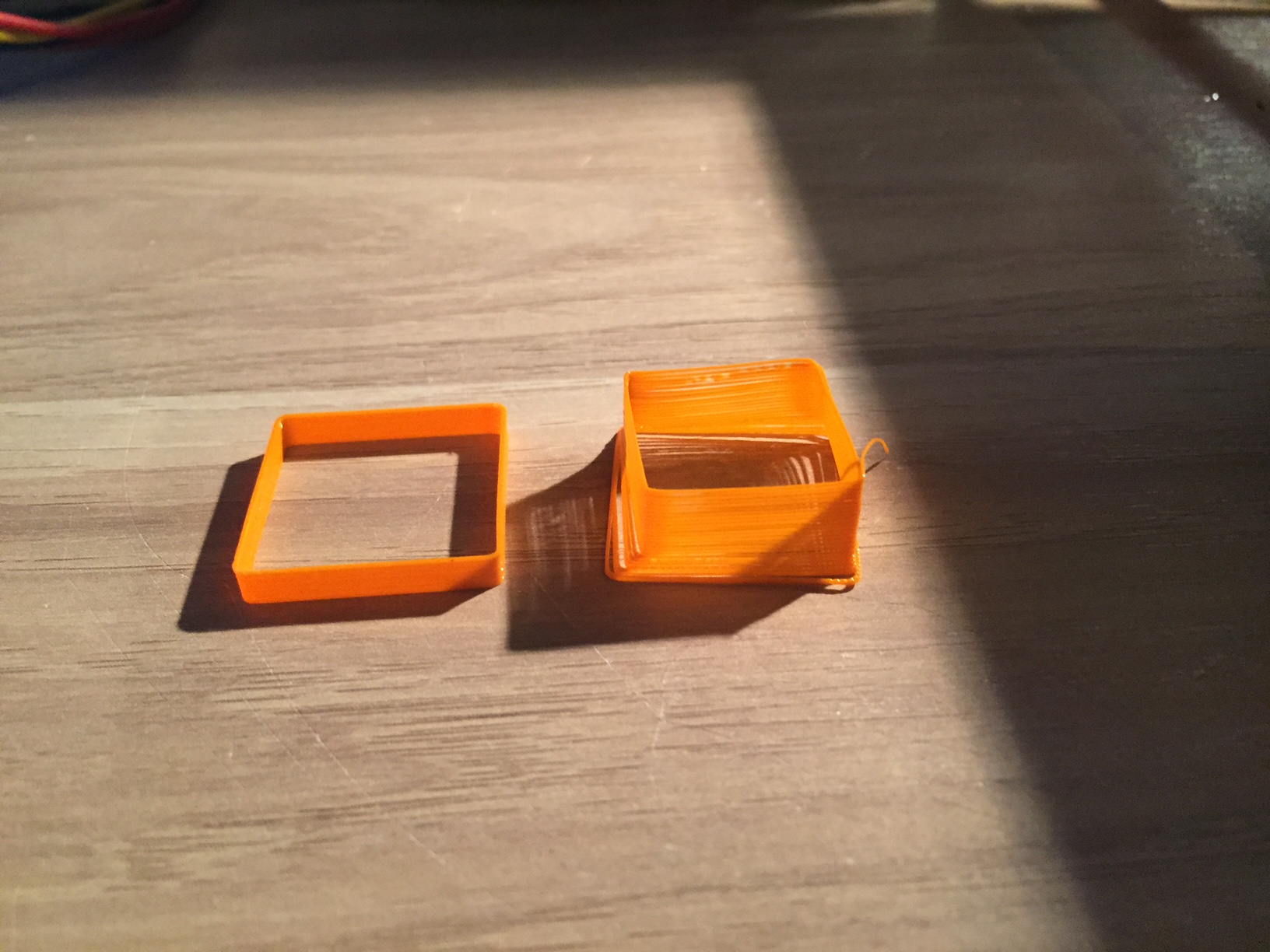
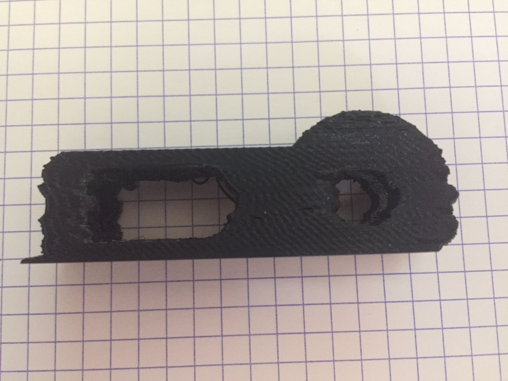
Résultat plutôt satisfaisant pour la Longueur, Largeur et Epaisseur conforme de 0,5mm, par contre en hauteur je n'ai obtenue que 3,5 mm au lieu des 10 mm attendus (cf pièce jointe).
J'ai donc fait le calcul pour modifier la valeur en Z soit : (1500x10) / 3,5 = 4285
Valeur que j'ai renseigné dans Marlin en Z via Config Eprom sous Repetier.
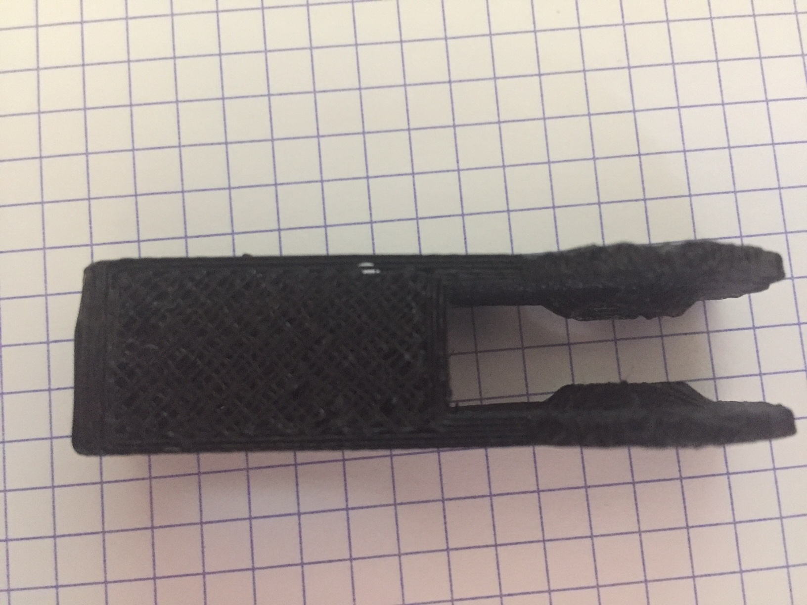
Relance d'une impression de test, et là je vois bien que ça va pas du tout, les couches sont trop espacés et ne solidarisent pas entre elle, donc déformation de la pièce (cf pièce jointe).
Je précise qu'avec la valeur Z=4285 j'ai fait une mesure lorsque je demande sous Repetier de monter de 10mm, l'imprimante monte bien de 10mm.
Je n'ai pas spécialement modifié de paramètre dans Slic3R.
Je n'arrive pas à comprendre ! Si je diminue cette valeur Z j'obtiens une belle pièce mais pas la bonne hauteur.
D'avance merci pour vos conseils et votre aide
J'ai récemment acquis d'occasion une Prusa i3 Rework 1.0, firmware Marlin sous Repetier avec carte Arduino Mega 2560 et Ramps 1.4, HeatBed MK3 et pour le moment juste une alim 12V de PC qui délivre 250W env.
Le montage mécanique s'est déroulé pratiquement sans accroc, juste une tête JHead MKV de bousillée (ventilateur positionné dans le mauvais sens soufflant vers l'ext)...et oui on apprends de ses erreurs
Achat donc d'un Extrudeur Hexagon 1,75mm/0,4mm
Par contre depuis plusieurs jours j'essaie de calibrer l'imprimante sans réel succès.
J'ai avant toute chose réalisé une calibration de mon Extrudeur avec du PLA.
Ensuite j'ai tenté l'impression du cube (layer height) 0,5 mm ci-après [www.thingiverse.com] avec les paramètres suivants :
X=80 Y=80 Z=1500 E=500
Résultat plutôt satisfaisant pour la Longueur, Largeur et Epaisseur conforme de 0,5mm, par contre en hauteur je n'ai obtenue que 3,5 mm au lieu des 10 mm attendus (cf pièce jointe).
J'ai donc fait le calcul pour modifier la valeur en Z soit : (1500x10) / 3,5 = 4285
Valeur que j'ai renseigné dans Marlin en Z via Config Eprom sous Repetier.
Relance d'une impression de test, et là je vois bien que ça va pas du tout, les couches sont trop espacés et ne solidarisent pas entre elle, donc déformation de la pièce (cf pièce jointe).
Je précise qu'avec la valeur Z=4285 j'ai fait une mesure lorsque je demande sous Repetier de monter de 10mm, l'imprimante monte bien de 10mm.
Je n'ai pas spécialement modifié de paramètre dans Slic3R.
Je n'arrive pas à comprendre ! Si je diminue cette valeur Z j'obtiens une belle pièce mais pas la bonne hauteur.
D'avance merci pour vos conseils et votre aide
|
Re: Prusa i3 Pb calibration Z August 29, 2016 09:22AM |
Registered: 8 years ago Posts: 489 |
Salut,
Sur ta 2eme photo, on dirait que tu as un décalage en x et y simultanément (effet d'escalier).
Est ce le cas ?
A côté de ça, si tes couches n'adhèrent pas entre elle, je dirais que tu n'extrudes plus assez.
As tu bien vérifié que lorsque tu demandais une extrusion de 10cm, tu avais bien 10cm de filament consommé ?
++
Ma Prusa i3 (ancienne imprimante, transformé en Itopie depuis)
Mon Itopie
Mon thingiverse
[TUTO] Lcd full graphic avec firmware Marlin
--
Possibilité de vous imprimer des pièces, n'hésitez pas à demander en MP
|
Re: Prusa i3 Pb calibration Z August 29, 2016 10:27AM |
Registered: 7 years ago Posts: 24 |
Quote
joyeufetar
Salut,
Sur ta 2eme photo, on dirait que tu as un décalage en x et y simultanément (effet d'escalier).
Est ce le cas ?
A côté de ça, si tes couches n'adhèrent pas entre elle, je dirais que tu n'extrudes plus assez.
As tu bien vérifié que lorsque tu demandais une extrusion de 10cm, tu avais bien 10cm de filament consommé ?
++
Oui j'ai bien un décallage en x et y.
J'ai pourtant commencé par la calibration de l'extrudeur et j'avais bien mesurer 100mm, je vais reprendre dans cette voie et augmenter le paramètre E.
J'avais un peu peur que ça augmente l'épaisseur.
Merci
|
Re: Prusa i3 Pb calibration Z August 29, 2016 10:40AM |
Registered: 8 years ago Posts: 489 |
C'est sans doute à cause de ton décalage alors si les couches n'adhèrent pas entre elles.
Tu as du toucher quelque chose.
Il faut :
- revérifier l'équerrage de la machine
- vérifier qu'il n'y a pas de point dur sur les axes x et y
- vérifier la tension appliqué au stepstick et l'ajuster en fonction
- vérifie si les problèmes persistent si tu n'alimentes pas le mk3 (alim trop faible).
Ma Prusa i3 (ancienne imprimante, transformé en Itopie depuis)
Mon Itopie
Mon thingiverse
[TUTO] Lcd full graphic avec firmware Marlin
--
Possibilité de vous imprimer des pièces, n'hésitez pas à demander en MP
|
Re: Prusa i3 Pb calibration Z August 29, 2016 10:54AM |
Registered: 7 years ago Posts: 24 |
Merci joyeufetar pour ton aide et tes conseils.
Je vais reprendre dans l'ordre
1/ nouvelle calibration de l'extrudeur
2/ vérifier Equerrage de la machine
non pas de point dur sur les axes X et Y
3/ comment je vérifie la tension appliqué au stepstick ?
4/ oui peut être un problème de puissance d'alimentation, je vais essayer sans faire chauffer le plateau.
Merci encore
|
Re: Prusa i3 Pb calibration Z August 29, 2016 02:19PM |
Registered: 8 years ago Posts: 489 |
Pour vérifier/régler la tension, voici un tuto vidéo qui explique comment le faire : [www.youtube.com]
Bien sur, si tu n'as pas des A4988, ça reste le même principe.
De toute façon, il te faut calculer les vref optimaux par rapport au matériel que tu as.
Ma Prusa i3 (ancienne imprimante, transformé en Itopie depuis)
Mon Itopie
Mon thingiverse
[TUTO] Lcd full graphic avec firmware Marlin
--
Possibilité de vous imprimer des pièces, n'hésitez pas à demander en MP
|
Re: Prusa i3 Pb calibration Z August 30, 2016 02:43AM |
Registered: 7 years ago Posts: 24 |
1/ Nouvelle calibration de l'extrudeur hier soir, de légères corrections mais vraiment minime.
2/ Equerrage de la machine vérifié, pas de problèmes apparents.
Avant de commencer à toucher à la tension des stepsticks, j'ai lancé une impression en gardant mes paramètres initiaux avec lesquels j'avais obtenu une belle pièce mais avec seulement 3,5mm de haut au lieu de 10mm, à savoir :
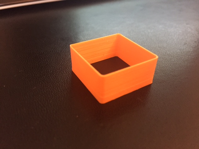
X=80 Y=80 Z=1500 (au lieu de 4285) E=505, (cf images) mais en modifiant l'échelle Z dans la partie placement d'objet, c'est à dire je l'ai monté à 2,86.
Et là miracle, un joli cube de test aux dimensions parfaites (cf image)
Donc est ce que ça peux venir des stepsticks ?
Au cas ou une copie du Marlin / configuration.h
#ifndef CONFIGURATION_H
#define CONFIGURATION_H
// This configuration file contains the basic settings.
// Advanced settings can be found in Configuration_adv.h
// BASIC SETTINGS: select your board type, temperature sensor type, axis scaling, and endstop configuration
// User-specified version info of this build to display in [Pronterface, etc] terminal window during
// startup. Implementation of an idea by Prof Braino to inform user that any changes made to this
// build by the user have been successfully uploaded into firmware.
#define STRING_VERSION_CONFIG_H __DATE__ " " __TIME__ // build date and time
#define STRING_CONFIG_H_AUTHOR "(none, default config)" // Who made the changes.
// SERIAL_PORT selects which serial port should be used for communication with the host.
// This allows the connection of wireless adapters (for instance) to non-default port pins.
// Serial port 0 is still used by the Arduino bootloader regardless of this setting.
#define SERIAL_PORT 0
// This determines the communication speed of the printer
//#define BAUDRATE 250000
#define BAUDRATE 115200
//// The following define selects which electronics board you have. Please choose the one that matches your setup
// 10 = Gen7 custom (Alfons3 Version) "https://github.com/Alfons3/Generation_7_Electronics"
// 11 = Gen7 v1.1, v1.2 = 11
// 12 = Gen7 v1.3
// 13 = Gen7 v1.4
// 3 = MEGA/RAMPS up to 1.2 = 3
// 33 = RAMPS 1.3 / 1.4 (Power outputs: Extruder, Fan, Bed)
// 34 = RAMPS 1.3 / 1.4 (Power outputs: Extruder0, Extruder1, Bed)
// 4 = Duemilanove w/ ATMega328P pin assignment
// 5 = Gen6
// 51 = Gen6 deluxe
// 6 = Sanguinololu < 1.2
// 62 = Sanguinololu 1.2 and above
// 63 = Melzi
// 64 = STB V1.1
// 65 = Azteeg X1
// 7 = Ultimaker
// 71 = Ultimaker (Older electronics. Pre 1.5.4. This is rare)
// 77 = 3Drag Controller
// 8 = Teensylu
// 80 = Rumba
// 81 = Printrboard (AT90USB1286)
// 82 = Brainwave (AT90USB646)
// 9 = Gen3+
// 70 = Megatronics
// 701= Megatronics v2.0
// 702= Minitronics v1.0
// 90 = Alpha OMCA board
// 91 = Final OMCA board
// 301 = Rambo
// 21 = Elefu Ra Board (v3)
#ifndef MOTHERBOARD
#define MOTHERBOARD 33
#endif
// Define this to set a custom name for your generic Mendel,
// #define CUSTOM_MENDEL_NAME "This Mendel"
// This defines the number of extruders
#define EXTRUDERS 1
//// The following define selects which power supply you have. Please choose the one that matches your setup
// 1 = ATX
// 2 = X-Box 360 203Watts (the blue wire connected to PS_ON and the red wire to VCC)
#define POWER_SUPPLY 1
//===========================================================================
//============================== Delta Settings =============================
//===========================================================================
// Enable DELTA kinematics
//#define DELTA
// Make delta curves from many straight lines (linear interpolation).
// This is a trade-off between visible corners (not enough segments)
// and processor overload (too many expensive sqrt calls).
#define DELTA_SEGMENTS_PER_SECOND 200
// Center-to-center distance of the holes in the diagonal push rods.
#define DELTA_DIAGONAL_ROD 250.0 // mm
// Horizontal offset from middle of printer to smooth rod center.
#define DELTA_SMOOTH_ROD_OFFSET 175.0 // mm
// Horizontal offset of the universal joints on the end effector.
#define DELTA_EFFECTOR_OFFSET 33.0 // mm
// Horizontal offset of the universal joints on the carriages.
#define DELTA_CARRIAGE_OFFSET 18.0 // mm
// Effective horizontal distance bridged by diagonal push rods.
#define DELTA_RADIUS (DELTA_SMOOTH_ROD_OFFSET-DELTA_EFFECTOR_OFFSET-DELTA_CARRIAGE_OFFSET)
// Effective X/Y positions of the three vertical towers.
#define SIN_60 0.8660254037844386
#define COS_60 0.5
#define DELTA_TOWER1_X -SIN_60*DELTA_RADIUS // front left tower
#define DELTA_TOWER1_Y -COS_60*DELTA_RADIUS
#define DELTA_TOWER2_X SIN_60*DELTA_RADIUS // front right tower
#define DELTA_TOWER2_Y -COS_60*DELTA_RADIUS
#define DELTA_TOWER3_X 0.0 // back middle tower
#define DELTA_TOWER3_Y DELTA_RADIUS
//===========================================================================
//=============================Thermal Settings ============================
//===========================================================================
//
//--NORMAL IS 4.7kohm PULLUP!-- 1kohm pullup can be used on hotend sensor, using correct resistor and table
//
//// Temperature sensor settings:
// -2 is thermocouple with MAX6675 (only for sensor 0)
// -1 is thermocouple with AD595
// 0 is not used
// 1 is 100k thermistor - best choice for EPCOS 100k (4.7k pullup)
// 2 is 200k thermistor - ATC Semitec 204GT-2 (4.7k pullup)
// 3 is mendel-parts thermistor (4.7k pullup)
// 4 is 10k thermistor !! do not use it for a hotend. It gives bad resolution at high temp. !!
// 5 is 100K thermistor - ATC Semitec 104GT-2 (Used in ParCan) (4.7k pullup)
// 6 is 100k EPCOS - Not as accurate as table 1 (created using a fluke thermocouple) (4.7k pullup)
// 7 is 100k Honeywell thermistor 135-104LAG-J01 (4.7k pullup)
// 8 is 100k 0603 SMD Vishay NTCS0603E3104FXT (4.7k pullup)
// 9 is 100k GE Sensing AL03006-58.2K-97-G1 (4.7k pullup)
// 10 is 100k RS thermistor 198-961 (4.7k pullup)
//
// 1k ohm pullup tables - This is not normal, you would have to have changed out your 4.7k for 1k
// (but gives greater accuracy and more stable PID)
// 51 is 100k thermistor - EPCOS (1k pullup)
// 52 is 200k thermistor - ATC Semitec 204GT-2 (1k pullup)
// 55 is 100k thermistor - ATC Semitec 104GT-2 (Used in ParCan) (1k pullup)
#define TEMP_SENSOR_0 1
#define TEMP_SENSOR_1 0
#define TEMP_SENSOR_2 0
#define TEMP_SENSOR_BED 1
// This makes temp sensor 1 a redundant sensor for sensor 0. If the temperatures difference between these sensors is to high the print will be aborted.
//#define TEMP_SENSOR_1_AS_REDUNDANT
#define MAX_REDUNDANT_TEMP_SENSOR_DIFF 10
// Actual temperature must be close to target for this long before M109 returns success
#define TEMP_RESIDENCY_TIME 10 // (seconds)
#define TEMP_HYSTERESIS 3 // (degC) range of +/- temperatures considered "close" to the target one
#define TEMP_WINDOW 1 // (degC) Window around target to start the residency timer x degC early.
// The minimal temperature defines the temperature below which the heater will not be enabled It is used
// to check that the wiring to the thermistor is not broken.
// Otherwise this would lead to the heater being powered on all the time.
#define HEATER_0_MINTEMP 5
#define HEATER_1_MINTEMP 5
#define HEATER_2_MINTEMP 5
#define BED_MINTEMP 5
// When temperature exceeds max temp, your heater will be switched off.
// This feature exists to protect your hotend from overheating accidentally, but *NOT* from thermistor short/failure!
// You should use MINTEMP for thermistor short/failure protection.
#define HEATER_0_MAXTEMP 275
#define HEATER_1_MAXTEMP 275
#define HEATER_2_MAXTEMP 275
#define BED_MAXTEMP 150
// If your bed has low resistance e.g. .6 ohm and throws the fuse you can duty cycle it to reduce the
// average current. The value should be an integer and the heat bed will be turned on for 1 interval of
// HEATER_BED_DUTY_CYCLE_DIVIDER intervals.
//#define HEATER_BED_DUTY_CYCLE_DIVIDER 4
// PID settings:
// Comment the following line to disable PID and enable bang-bang.
#define PIDTEMP
#define BANG_MAX 255 // limits current to nozzle while in bang-bang mode; 255=full current
#define PID_MAX 255 // limits current to nozzle while PID is active (see PID_FUNCTIONAL_RANGE below); 255=full current
#ifdef PIDTEMP
//#define PID_DEBUG // Sends debug data to the serial port.
//#define PID_OPENLOOP 1 // Puts PID in open loop. M104/M140 sets the output power from 0 to PID_MAX
#define PID_FUNCTIONAL_RANGE 10 // If the temperature difference between the target temperature and the actual temperature
// is more then PID_FUNCTIONAL_RANGE then the PID will be shut off and the heater will be set to min/max.
#define PID_INTEGRAL_DRIVE_MAX 255 //limit for the integral term
#define K1 0.95 //smoothing factor within the PID
#define PID_dT ((16.0 * 8.0)/(F_CPU / 64.0 / 256.0)) //sampling period of the temperature routine
// If you are using a preconfigured hotend then you can use one of the value sets by uncommenting it
// Ultimaker
#define DEFAULT_Kp 22.2
#define DEFAULT_Ki 1.08
#define DEFAULT_Kd 114
// Makergear
// #define DEFAULT_Kp 7.0
// #define DEFAULT_Ki 0.1
// #define DEFAULT_Kd 12
// Mendel Parts V9 on 12V
// #define DEFAULT_Kp 63.0
// #define DEFAULT_Ki 2.25
// #define DEFAULT_Kd 440
#endif // PIDTEMP
// Bed Temperature Control
// Select PID or bang-bang with PIDTEMPBED. If bang-bang, BED_LIMIT_SWITCHING will enable hysteresis
//
// Uncomment this to enable PID on the bed. It uses the same frequency PWM as the extruder.
// If your PID_dT above is the default, and correct for your hardware/configuration, that means 7.689Hz,
// which is fine for driving a square wave into a resistive load and does not significantly impact you FET heating.
// This also works fine on a Fotek SSR-10DA Solid State Relay into a 250W heater.
// If your configuration is significantly different than this and you don't understand the issues involved, you probably
// shouldn't use bed PID until someone else verifies your hardware works.
// If this is enabled, find your own PID constants below.
//#define PIDTEMPBED
//
//#define BED_LIMIT_SWITCHING
// This sets the max power delivered to the bed, and replaces the HEATER_BED_DUTY_CYCLE_DIVIDER option.
// all forms of bed control obey this (PID, bang-bang, bang-bang with hysteresis)
// setting this to anything other than 255 enables a form of PWM to the bed just like HEATER_BED_DUTY_CYCLE_DIVIDER did,
// so you shouldn't use it unless you are OK with PWM on your bed. (see the comment on enabling PIDTEMPBED)
#define MAX_BED_POWER 255 // limits duty cycle to bed; 255=full current
#ifdef PIDTEMPBED
//120v 250W silicone heater into 4mm borosilicate (MendelMax 1.5+)
//from FOPDT model - kp=.39 Tp=405 Tdead=66, Tc set to 79.2, aggressive factor of .15 (vs .1, 1, 10)
#define DEFAULT_bedKp 10.00
#define DEFAULT_bedKi .023
#define DEFAULT_bedKd 305.4
//120v 250W silicone heater into 4mm borosilicate (MendelMax 1.5+)
//from pidautotune
// #define DEFAULT_bedKp 97.1
// #define DEFAULT_bedKi 1.41
// #define DEFAULT_bedKd 1675.16
// FIND YOUR OWN: "M303 E-1 C8 S90" to run autotune on the bed at 90 degreesC for 8 cycles.
#endif // PIDTEMPBED
//this prevents dangerous Extruder moves, i.e. if the temperature is under the limit
//can be software-disabled for whatever purposes by
#define PREVENT_DANGEROUS_EXTRUDE
//if PREVENT_DANGEROUS_EXTRUDE is on, you can still disable (uncomment) very long bits of extrusion separately.
#define PREVENT_LENGTHY_EXTRUDE
#define EXTRUDE_MINTEMP 170
#define EXTRUDE_MAXLENGTH (X_MAX_LENGTH+Y_MAX_LENGTH) //prevent extrusion of very large distances.
//===========================================================================
//=============================Mechanical Settings===========================
//===========================================================================
// Uncomment the following line to enable CoreXY kinematics
// #define COREXY
// coarse Endstop Settings
#define ENDSTOPPULLUPS // Comment this out (using // at the start of the line) to disable the endstop pullup resistors
#ifndef ENDSTOPPULLUPS
// fine Enstop settings: Individual Pullups. will be ignored if ENDSTOPPULLUPS is defined
#define ENDSTOPPULLUP_XMAX
#define ENDSTOPPULLUP_YMAX
#define ENDSTOPPULLUP_ZMAX
#define ENDSTOPPULLUP_XMIN
#define ENDSTOPPULLUP_YMIN
//#define ENDSTOPPULLUP_ZMIN
#endif
#ifdef ENDSTOPPULLUPS
#define ENDSTOPPULLUP_XMAX
#define ENDSTOPPULLUP_YMAX
#define ENDSTOPPULLUP_ZMAX
#define ENDSTOPPULLUP_XMIN
#define ENDSTOPPULLUP_YMIN
#define ENDSTOPPULLUP_ZMIN
#endif
// The pullups are needed if you directly connect a mechanical endswitch between the signal and ground pins.
const bool X_ENDSTOPS_INVERTING = true; // set to true to invert the logic of the endstops.
const bool Y_ENDSTOPS_INVERTING = true; // set to true to invert the logic of the endstops.
const bool Z_ENDSTOPS_INVERTING = true; // set to true to invert the logic of the endstops.
//#define DISABLE_MAX_ENDSTOPS
//#define DISABLE_MIN_ENDSTOPS
// Disable max endstops for compatibility with endstop checking routine
#if defined(COREXY) && !defined(DISABLE_MAX_ENDSTOPS)
#define DISABLE_MAX_ENDSTOPS
#endif
// For Inverting Stepper Enable Pins (Active Low) use 0, Non Inverting (Active High) use 1
#define X_ENABLE_ON 0
#define Y_ENABLE_ON 0
#define Z_ENABLE_ON 0
#define E_ENABLE_ON 0 // For all extruders
// Disables axis when it's not being used.
#define DISABLE_X false
#define DISABLE_Y false
#define DISABLE_Z false
#define DISABLE_E false // For all extruders
#define INVERT_X_DIR true // for Mendel set to false, for Orca set to true
#define INVERT_Y_DIR true // for Mendel set to true, for Orca set to false
#define INVERT_Z_DIR true // for Mendel set to false, for Orca set to true
#define INVERT_E0_DIR true // for direct drive extruder v9 set to true, for geared extruder set to false
#define INVERT_E1_DIR false // for direct drive extruder v9 set to true, for geared extruder set to false
#define INVERT_E2_DIR false // for direct drive extruder v9 set to true, for geared extruder set to false
// ENDSTOP SETTINGS:
// Sets direction of endstops when homing; 1=MAX, -1=MIN
#define X_HOME_DIR -1
#define Y_HOME_DIR -1
#define Z_HOME_DIR -1
#define min_software_endstops true // If true, axis won't move to coordinates less than HOME_POS.
#define max_software_endstops true // If true, axis won't move to coordinates greater than the defined lengths below.
// Travel limits after homing
#define X_MAX_POS 200
#define X_MIN_POS 0
#define Y_MAX_POS 200
#define Y_MIN_POS 0
#define Z_MAX_POS 180
#define Z_MIN_POS 0
#define X_MAX_LENGTH (X_MAX_POS - X_MIN_POS)
#define Y_MAX_LENGTH (Y_MAX_POS - Y_MIN_POS)
#define Z_MAX_LENGTH (Z_MAX_POS - Z_MIN_POS)
// The position of the homing switches
//#define MANUAL_HOME_POSITIONS // If defined, MANUAL_*_HOME_POS below will be used
//#define BED_CENTER_AT_0_0 // If defined, the center of the bed is at (X=0, Y=0)
//Manual homing switch locations:
// For deltabots this means top and center of the cartesian print volume.
#define MANUAL_X_HOME_POS 0
#define MANUAL_Y_HOME_POS 0
#define MANUAL_Z_HOME_POS 0
//#define MANUAL_Z_HOME_POS 402 // For delta: Distance between nozzle and print surface after homing.
//// MOVEMENT SETTINGS
#define NUM_AXIS 4 // The axis order in all axis related arrays is X, Y, Z, E
#define HOMING_FEEDRATE {50*60, 50*60, 3*60, 0} // set the homing speeds (mm/min)
// default settings
#define DEFAULT_AXIS_STEPS_PER_UNIT {81.4,81.4,4000,654.8} // default steps per unit for Ultimaker
#define DEFAULT_MAX_FEEDRATE {500, 500, 3, 25} // (mm/sec)
#define DEFAULT_MAX_ACCELERATION {2000,2000,20,1000} // X, Y, Z, E maximum start speed for accelerated moves. E default values are good for skeinforge 40+, for older versions raise them a lot.
#define DEFAULT_ACCELERATION 2000 // X, Y, Z and E max acceleration in mm/s^2 for printing moves
#define DEFAULT_RETRACT_ACCELERATION 2000 // X, Y, Z and E max acceleration in mm/s^2 for retracts
// Offset of the extruders (uncomment if using more than one and relying on firmware to position when changing).
// The offset has to be X=0, Y=0 for the extruder 0 hotend (default extruder).
// For the other hotends it is their distance from the extruder 0 hotend.
// #define EXTRUDER_OFFSET_X {0.0, 20.00} // (in mm) for each extruder, offset of the hotend on the X axis
// #define EXTRUDER_OFFSET_Y {0.0, 5.00} // (in mm) for each extruder, offset of the hotend on the Y axis
// The speed change that does not require acceleration (i.e. the software might assume it can be done instantaneously)
#define DEFAULT_XYJERK 20.0 // (mm/sec)
#define DEFAULT_ZJERK 0.4 // (mm/sec)
#define DEFAULT_EJERK 5.0 // (mm/sec)
//===========================================================================
//=============================Additional Features===========================
//===========================================================================
// EEPROM
// the microcontroller can store settings in the EEPROM, e.g. max velocity...
// M500 - stores paramters in EEPROM
// M501 - reads parameters from EEPROM (if you need reset them after you changed them temporarily).
// M502 - reverts to the default "factory settings". You still need to store them in EEPROM afterwards if you want to.
//define this to enable eeprom support
#define EEPROM_SETTINGS
//to disable EEPROM Serial responses and decrease program space by ~1700 byte: comment this out:
// please keep turned on if you can.
#define EEPROM_CHITCHAT
// Preheat Constants
#define PLA_PREHEAT_HOTEND_TEMP 180
#define PLA_PREHEAT_HPB_TEMP 70
#define PLA_PREHEAT_FAN_SPEED 255 // Insert Value between 0 and 255
#define ABS_PREHEAT_HOTEND_TEMP 240
#define ABS_PREHEAT_HPB_TEMP 100
#define ABS_PREHEAT_FAN_SPEED 255 // Insert Value between 0 and 255
//LCD and SD support
//#define ULTRA_LCD //general lcd support, also 16x2
//#define DOGLCD // Support for SPI LCD 128x64 (Controller ST7565R graphic Display Family)
#define SDSUPPORT // Enable SD Card Support in Hardware Console
//#define SDSLOW // Use slower SD transfer mode (not normally needed - uncomment if you're getting volume init error)
//#define ULTIMAKERCONTROLLER //as available from the ultimaker online store.
//#define ULTIPANEL //the ultipanel as on thingiverse
// The RepRapDiscount Smart Controller (white PC
// [reprap.org]
// #define REPRAP_DISCOUNT_SMART_CONTROLLER
// The GADGETS3D G3D LCD/SD Controller (blue PC
// [reprap.org]
//#define G3D_PANEL
// The RepRapDiscount FULL GRAPHIC Smart Controller (quadratic white PC
// [reprap.org]
//
// ==> REMEMBER TO INSTALL U8glib to your ARDUINO library folder: [code.google.com]
#define REPRAP_DISCOUNT_FULL_GRAPHIC_SMART_CONTROLLER
// The RepRapWorld REPRAPWORLD_KEYPAD v1.1
// [reprapworld.com]
//#define REPRAPWORLD_KEYPAD
//#define REPRAPWORLD_KEYPAD_MOVE_STEP 10.0 // how much should be moved when a key is pressed, eg 10.0 means 10mm per click
// The Elefu RA Board Control Panel
// [www.elefu.com]
// REMEMBER TO INSTALL LiquidCrystal_I2C.h in your ARUDINO library folder: [github.com]
//#define RA_CONTROL_PANEL
//automatic expansion
#if defined (REPRAP_DISCOUNT_FULL_GRAPHIC_SMART_CONTROLLER)
#define DOGLCD
#define U8GLIB_ST7920
#define REPRAP_DISCOUNT_SMART_CONTROLLER
#endif
#if defined(ULTIMAKERCONTROLLER) || defined(REPRAP_DISCOUNT_SMART_CONTROLLER) || defined(G3D_PANEL)
#define ULTIPANEL
#define NEWPANEL
#endif
#if defined(REPRAPWORLD_KEYPAD)
#define NEWPANEL
#define ULTIPANEL
#endif
#if defined(RA_CONTROL_PANEL)
#define ULTIPANEL
#define NEWPANEL
#define LCD_I2C_TYPE_PCA8574
#define LCD_I2C_ADDRESS 0x27 // I2C Address of the port expander
#endif
//I2C PANELS
//#define LCD_I2C_SAINSMART_YWROBOT
#ifdef LCD_I2C_SAINSMART_YWROBOT
// This uses the LiquidCrystal_I2C library ( [bitbucket.org] )
// Make sure it is placed in the Arduino libraries directory.
#define LCD_I2C_TYPE_PCF8575
#define LCD_I2C_ADDRESS 0x27 // I2C Address of the port expander
#define NEWPANEL
#define ULTIPANEL
#endif
// PANELOLU2 LCD with status LEDs, separate encoder and click inputs
//#define LCD_I2C_PANELOLU2
#ifdef LCD_I2C_PANELOLU2
// This uses the LiquidTWI2 library v1.2.3 or later ( [github.com] )
// Make sure the LiquidTWI2 directory is placed in the Arduino or Sketchbook libraries subdirectory.
// (v1.2.3 no longer requires you to define PANELOLU in the LiquidTWI2.h library header file)
// Note: The PANELOLU2 encoder click input can either be directly connected to a pin
// (if BTN_ENC defined to != -1) or read through I2C (when BTN_ENC == -1).
#define LCD_I2C_TYPE_MCP23017
#define LCD_I2C_ADDRESS 0x20 // I2C Address of the port expander
#define LCD_USE_I2C_BUZZER //comment out to disable buzzer on LCD
#define NEWPANEL
#define ULTIPANEL
#endif
// Panucatt VIKI LCD with status LEDs, integrated click & L/R/U/P buttons, separate encoder inputs
//#define LCD_I2C_VIKI
#ifdef LCD_I2C_VIKI
// This uses the LiquidTWI2 library v1.2.3 or later ( [github.com] )
// Make sure the LiquidTWI2 directory is placed in the Arduino or Sketchbook libraries subdirectory.
// Note: The pause/stop/resume LCD button pin should be connected to the Arduino
// BTN_ENC pin (or set BTN_ENC to -1 if not used)
#define LCD_I2C_TYPE_MCP23017
#define LCD_I2C_ADDRESS 0x20 // I2C Address of the port expander
#define LCD_USE_I2C_BUZZER //comment out to disable buzzer on LCD (requires LiquidTWI2 v1.2.3 or later)
#define NEWPANEL
#define ULTIPANEL
#endif
#ifdef ULTIPANEL
// #define NEWPANEL //enable this if you have a click-encoder panel
#define SDSUPPORT
#define ULTRA_LCD
#ifdef DOGLCD // Change number of lines to match the DOG graphic display
#define LCD_WIDTH 20
#define LCD_HEIGHT 5
#else
#define LCD_WIDTH 20
#define LCD_HEIGHT 4
#endif
#else //no panel but just lcd
#ifdef ULTRA_LCD
#ifdef DOGLCD // Change number of lines to match the 128x64 graphics display
#define LCD_WIDTH 20
#define LCD_HEIGHT 5
#else
#define LCD_WIDTH 16
#define LCD_HEIGHT 2
#endif
#endif
#endif
// Increase the FAN pwm frequency. Removes the PWM noise but increases heating in the FET/Arduino
//#define FAST_PWM_FAN
// Use software PWM to drive the fan, as for the heaters. This uses a very low frequency
// which is not ass annoying as with the hardware PWM. On the other hand, if this frequency
// is too low, you should also increment SOFT_PWM_SCALE.
//#define FAN_SOFT_PWM
// Incrementing this by 1 will double the software PWM frequency,
// affecting heaters, and the fan if FAN_SOFT_PWM is enabled.
// However, control resolution will be halved for each increment;
// at zero value, there are 128 effective control positions.
#define SOFT_PWM_SCALE 0
// M240 Triggers a camera by emulating a Canon RC-1 Remote
// Data from: [www.doc-diy.net]
// #define PHOTOGRAPH_PIN 23
// SF send wrong arc g-codes when using Arc Point as fillet procedure
//#define SF_ARC_FIX
// Support for the BariCUDA Paste Extruder.
//#define BARICUDA
/*********************************************************************\
* R/C SERVO support
* Sponsored by TrinityLabs, Reworked by codexmas
**********************************************************************/
// Number of servos
//
// If you select a configuration below, this will receive a default value and does not need to be set manually
// set it manually if you have more servos than extruders and wish to manually control some
// leaving it undefined or defining as 0 will disable the servo subsystem
// If unsure, leave commented / disabled
//
//#define NUM_SERVOS 3 // Servo index starts with 0 for M280 command
// Servo Endstops
//
// This allows for servo actuated endstops, primary usage is for the Z Axis to eliminate calibration or bed height changes.
// Use M206 command to correct for switch height offset to actual nozzle height. Store that setting with M500.
//
//#define SERVO_ENDSTOPS {-1, -1, 0} // Servo index for X, Y, Z. Disable with -1
//#define SERVO_ENDSTOP_ANGLES {0,0, 0,0, 70,0} // X,Y,Z Axis Extend and Retract angles
#include "Configuration_adv.h"
#include "thermistortables.h"
#endif //__CONFIGURATION_H
2/ Equerrage de la machine vérifié, pas de problèmes apparents.
Avant de commencer à toucher à la tension des stepsticks, j'ai lancé une impression en gardant mes paramètres initiaux avec lesquels j'avais obtenu une belle pièce mais avec seulement 3,5mm de haut au lieu de 10mm, à savoir :
X=80 Y=80 Z=1500 (au lieu de 4285) E=505, (cf images) mais en modifiant l'échelle Z dans la partie placement d'objet, c'est à dire je l'ai monté à 2,86.
Et là miracle, un joli cube de test aux dimensions parfaites (cf image)
Donc est ce que ça peux venir des stepsticks ?
Au cas ou une copie du Marlin / configuration.h
#ifndef CONFIGURATION_H
#define CONFIGURATION_H
// This configuration file contains the basic settings.
// Advanced settings can be found in Configuration_adv.h
// BASIC SETTINGS: select your board type, temperature sensor type, axis scaling, and endstop configuration
// User-specified version info of this build to display in [Pronterface, etc] terminal window during
// startup. Implementation of an idea by Prof Braino to inform user that any changes made to this
// build by the user have been successfully uploaded into firmware.
#define STRING_VERSION_CONFIG_H __DATE__ " " __TIME__ // build date and time
#define STRING_CONFIG_H_AUTHOR "(none, default config)" // Who made the changes.
// SERIAL_PORT selects which serial port should be used for communication with the host.
// This allows the connection of wireless adapters (for instance) to non-default port pins.
// Serial port 0 is still used by the Arduino bootloader regardless of this setting.
#define SERIAL_PORT 0
// This determines the communication speed of the printer
//#define BAUDRATE 250000
#define BAUDRATE 115200
//// The following define selects which electronics board you have. Please choose the one that matches your setup
// 10 = Gen7 custom (Alfons3 Version) "https://github.com/Alfons3/Generation_7_Electronics"
// 11 = Gen7 v1.1, v1.2 = 11
// 12 = Gen7 v1.3
// 13 = Gen7 v1.4
// 3 = MEGA/RAMPS up to 1.2 = 3
// 33 = RAMPS 1.3 / 1.4 (Power outputs: Extruder, Fan, Bed)
// 34 = RAMPS 1.3 / 1.4 (Power outputs: Extruder0, Extruder1, Bed)
// 4 = Duemilanove w/ ATMega328P pin assignment
// 5 = Gen6
// 51 = Gen6 deluxe
// 6 = Sanguinololu < 1.2
// 62 = Sanguinololu 1.2 and above
// 63 = Melzi
// 64 = STB V1.1
// 65 = Azteeg X1
// 7 = Ultimaker
// 71 = Ultimaker (Older electronics. Pre 1.5.4. This is rare)
// 77 = 3Drag Controller
// 8 = Teensylu
// 80 = Rumba
// 81 = Printrboard (AT90USB1286)
// 82 = Brainwave (AT90USB646)
// 9 = Gen3+
// 70 = Megatronics
// 701= Megatronics v2.0
// 702= Minitronics v1.0
// 90 = Alpha OMCA board
// 91 = Final OMCA board
// 301 = Rambo
// 21 = Elefu Ra Board (v3)
#ifndef MOTHERBOARD
#define MOTHERBOARD 33
#endif
// Define this to set a custom name for your generic Mendel,
// #define CUSTOM_MENDEL_NAME "This Mendel"
// This defines the number of extruders
#define EXTRUDERS 1
//// The following define selects which power supply you have. Please choose the one that matches your setup
// 1 = ATX
// 2 = X-Box 360 203Watts (the blue wire connected to PS_ON and the red wire to VCC)
#define POWER_SUPPLY 1
//===========================================================================
//============================== Delta Settings =============================
//===========================================================================
// Enable DELTA kinematics
//#define DELTA
// Make delta curves from many straight lines (linear interpolation).
// This is a trade-off between visible corners (not enough segments)
// and processor overload (too many expensive sqrt calls).
#define DELTA_SEGMENTS_PER_SECOND 200
// Center-to-center distance of the holes in the diagonal push rods.
#define DELTA_DIAGONAL_ROD 250.0 // mm
// Horizontal offset from middle of printer to smooth rod center.
#define DELTA_SMOOTH_ROD_OFFSET 175.0 // mm
// Horizontal offset of the universal joints on the end effector.
#define DELTA_EFFECTOR_OFFSET 33.0 // mm
// Horizontal offset of the universal joints on the carriages.
#define DELTA_CARRIAGE_OFFSET 18.0 // mm
// Effective horizontal distance bridged by diagonal push rods.
#define DELTA_RADIUS (DELTA_SMOOTH_ROD_OFFSET-DELTA_EFFECTOR_OFFSET-DELTA_CARRIAGE_OFFSET)
// Effective X/Y positions of the three vertical towers.
#define SIN_60 0.8660254037844386
#define COS_60 0.5
#define DELTA_TOWER1_X -SIN_60*DELTA_RADIUS // front left tower
#define DELTA_TOWER1_Y -COS_60*DELTA_RADIUS
#define DELTA_TOWER2_X SIN_60*DELTA_RADIUS // front right tower
#define DELTA_TOWER2_Y -COS_60*DELTA_RADIUS
#define DELTA_TOWER3_X 0.0 // back middle tower
#define DELTA_TOWER3_Y DELTA_RADIUS
//===========================================================================
//=============================Thermal Settings ============================
//===========================================================================
//
//--NORMAL IS 4.7kohm PULLUP!-- 1kohm pullup can be used on hotend sensor, using correct resistor and table
//
//// Temperature sensor settings:
// -2 is thermocouple with MAX6675 (only for sensor 0)
// -1 is thermocouple with AD595
// 0 is not used
// 1 is 100k thermistor - best choice for EPCOS 100k (4.7k pullup)
// 2 is 200k thermistor - ATC Semitec 204GT-2 (4.7k pullup)
// 3 is mendel-parts thermistor (4.7k pullup)
// 4 is 10k thermistor !! do not use it for a hotend. It gives bad resolution at high temp. !!
// 5 is 100K thermistor - ATC Semitec 104GT-2 (Used in ParCan) (4.7k pullup)
// 6 is 100k EPCOS - Not as accurate as table 1 (created using a fluke thermocouple) (4.7k pullup)
// 7 is 100k Honeywell thermistor 135-104LAG-J01 (4.7k pullup)
// 8 is 100k 0603 SMD Vishay NTCS0603E3104FXT (4.7k pullup)
// 9 is 100k GE Sensing AL03006-58.2K-97-G1 (4.7k pullup)
// 10 is 100k RS thermistor 198-961 (4.7k pullup)
//
// 1k ohm pullup tables - This is not normal, you would have to have changed out your 4.7k for 1k
// (but gives greater accuracy and more stable PID)
// 51 is 100k thermistor - EPCOS (1k pullup)
// 52 is 200k thermistor - ATC Semitec 204GT-2 (1k pullup)
// 55 is 100k thermistor - ATC Semitec 104GT-2 (Used in ParCan) (1k pullup)
#define TEMP_SENSOR_0 1
#define TEMP_SENSOR_1 0
#define TEMP_SENSOR_2 0
#define TEMP_SENSOR_BED 1
// This makes temp sensor 1 a redundant sensor for sensor 0. If the temperatures difference between these sensors is to high the print will be aborted.
//#define TEMP_SENSOR_1_AS_REDUNDANT
#define MAX_REDUNDANT_TEMP_SENSOR_DIFF 10
// Actual temperature must be close to target for this long before M109 returns success
#define TEMP_RESIDENCY_TIME 10 // (seconds)
#define TEMP_HYSTERESIS 3 // (degC) range of +/- temperatures considered "close" to the target one
#define TEMP_WINDOW 1 // (degC) Window around target to start the residency timer x degC early.
// The minimal temperature defines the temperature below which the heater will not be enabled It is used
// to check that the wiring to the thermistor is not broken.
// Otherwise this would lead to the heater being powered on all the time.
#define HEATER_0_MINTEMP 5
#define HEATER_1_MINTEMP 5
#define HEATER_2_MINTEMP 5
#define BED_MINTEMP 5
// When temperature exceeds max temp, your heater will be switched off.
// This feature exists to protect your hotend from overheating accidentally, but *NOT* from thermistor short/failure!
// You should use MINTEMP for thermistor short/failure protection.
#define HEATER_0_MAXTEMP 275
#define HEATER_1_MAXTEMP 275
#define HEATER_2_MAXTEMP 275
#define BED_MAXTEMP 150
// If your bed has low resistance e.g. .6 ohm and throws the fuse you can duty cycle it to reduce the
// average current. The value should be an integer and the heat bed will be turned on for 1 interval of
// HEATER_BED_DUTY_CYCLE_DIVIDER intervals.
//#define HEATER_BED_DUTY_CYCLE_DIVIDER 4
// PID settings:
// Comment the following line to disable PID and enable bang-bang.
#define PIDTEMP
#define BANG_MAX 255 // limits current to nozzle while in bang-bang mode; 255=full current
#define PID_MAX 255 // limits current to nozzle while PID is active (see PID_FUNCTIONAL_RANGE below); 255=full current
#ifdef PIDTEMP
//#define PID_DEBUG // Sends debug data to the serial port.
//#define PID_OPENLOOP 1 // Puts PID in open loop. M104/M140 sets the output power from 0 to PID_MAX
#define PID_FUNCTIONAL_RANGE 10 // If the temperature difference between the target temperature and the actual temperature
// is more then PID_FUNCTIONAL_RANGE then the PID will be shut off and the heater will be set to min/max.
#define PID_INTEGRAL_DRIVE_MAX 255 //limit for the integral term
#define K1 0.95 //smoothing factor within the PID
#define PID_dT ((16.0 * 8.0)/(F_CPU / 64.0 / 256.0)) //sampling period of the temperature routine
// If you are using a preconfigured hotend then you can use one of the value sets by uncommenting it
// Ultimaker
#define DEFAULT_Kp 22.2
#define DEFAULT_Ki 1.08
#define DEFAULT_Kd 114
// Makergear
// #define DEFAULT_Kp 7.0
// #define DEFAULT_Ki 0.1
// #define DEFAULT_Kd 12
// Mendel Parts V9 on 12V
// #define DEFAULT_Kp 63.0
// #define DEFAULT_Ki 2.25
// #define DEFAULT_Kd 440
#endif // PIDTEMP
// Bed Temperature Control
// Select PID or bang-bang with PIDTEMPBED. If bang-bang, BED_LIMIT_SWITCHING will enable hysteresis
//
// Uncomment this to enable PID on the bed. It uses the same frequency PWM as the extruder.
// If your PID_dT above is the default, and correct for your hardware/configuration, that means 7.689Hz,
// which is fine for driving a square wave into a resistive load and does not significantly impact you FET heating.
// This also works fine on a Fotek SSR-10DA Solid State Relay into a 250W heater.
// If your configuration is significantly different than this and you don't understand the issues involved, you probably
// shouldn't use bed PID until someone else verifies your hardware works.
// If this is enabled, find your own PID constants below.
//#define PIDTEMPBED
//
//#define BED_LIMIT_SWITCHING
// This sets the max power delivered to the bed, and replaces the HEATER_BED_DUTY_CYCLE_DIVIDER option.
// all forms of bed control obey this (PID, bang-bang, bang-bang with hysteresis)
// setting this to anything other than 255 enables a form of PWM to the bed just like HEATER_BED_DUTY_CYCLE_DIVIDER did,
// so you shouldn't use it unless you are OK with PWM on your bed. (see the comment on enabling PIDTEMPBED)
#define MAX_BED_POWER 255 // limits duty cycle to bed; 255=full current
#ifdef PIDTEMPBED
//120v 250W silicone heater into 4mm borosilicate (MendelMax 1.5+)
//from FOPDT model - kp=.39 Tp=405 Tdead=66, Tc set to 79.2, aggressive factor of .15 (vs .1, 1, 10)
#define DEFAULT_bedKp 10.00
#define DEFAULT_bedKi .023
#define DEFAULT_bedKd 305.4
//120v 250W silicone heater into 4mm borosilicate (MendelMax 1.5+)
//from pidautotune
// #define DEFAULT_bedKp 97.1
// #define DEFAULT_bedKi 1.41
// #define DEFAULT_bedKd 1675.16
// FIND YOUR OWN: "M303 E-1 C8 S90" to run autotune on the bed at 90 degreesC for 8 cycles.
#endif // PIDTEMPBED
//this prevents dangerous Extruder moves, i.e. if the temperature is under the limit
//can be software-disabled for whatever purposes by
#define PREVENT_DANGEROUS_EXTRUDE
//if PREVENT_DANGEROUS_EXTRUDE is on, you can still disable (uncomment) very long bits of extrusion separately.
#define PREVENT_LENGTHY_EXTRUDE
#define EXTRUDE_MINTEMP 170
#define EXTRUDE_MAXLENGTH (X_MAX_LENGTH+Y_MAX_LENGTH) //prevent extrusion of very large distances.
//===========================================================================
//=============================Mechanical Settings===========================
//===========================================================================
// Uncomment the following line to enable CoreXY kinematics
// #define COREXY
// coarse Endstop Settings
#define ENDSTOPPULLUPS // Comment this out (using // at the start of the line) to disable the endstop pullup resistors
#ifndef ENDSTOPPULLUPS
// fine Enstop settings: Individual Pullups. will be ignored if ENDSTOPPULLUPS is defined
#define ENDSTOPPULLUP_XMAX
#define ENDSTOPPULLUP_YMAX
#define ENDSTOPPULLUP_ZMAX
#define ENDSTOPPULLUP_XMIN
#define ENDSTOPPULLUP_YMIN
//#define ENDSTOPPULLUP_ZMIN
#endif
#ifdef ENDSTOPPULLUPS
#define ENDSTOPPULLUP_XMAX
#define ENDSTOPPULLUP_YMAX
#define ENDSTOPPULLUP_ZMAX
#define ENDSTOPPULLUP_XMIN
#define ENDSTOPPULLUP_YMIN
#define ENDSTOPPULLUP_ZMIN
#endif
// The pullups are needed if you directly connect a mechanical endswitch between the signal and ground pins.
const bool X_ENDSTOPS_INVERTING = true; // set to true to invert the logic of the endstops.
const bool Y_ENDSTOPS_INVERTING = true; // set to true to invert the logic of the endstops.
const bool Z_ENDSTOPS_INVERTING = true; // set to true to invert the logic of the endstops.
//#define DISABLE_MAX_ENDSTOPS
//#define DISABLE_MIN_ENDSTOPS
// Disable max endstops for compatibility with endstop checking routine
#if defined(COREXY) && !defined(DISABLE_MAX_ENDSTOPS)
#define DISABLE_MAX_ENDSTOPS
#endif
// For Inverting Stepper Enable Pins (Active Low) use 0, Non Inverting (Active High) use 1
#define X_ENABLE_ON 0
#define Y_ENABLE_ON 0
#define Z_ENABLE_ON 0
#define E_ENABLE_ON 0 // For all extruders
// Disables axis when it's not being used.
#define DISABLE_X false
#define DISABLE_Y false
#define DISABLE_Z false
#define DISABLE_E false // For all extruders
#define INVERT_X_DIR true // for Mendel set to false, for Orca set to true
#define INVERT_Y_DIR true // for Mendel set to true, for Orca set to false
#define INVERT_Z_DIR true // for Mendel set to false, for Orca set to true
#define INVERT_E0_DIR true // for direct drive extruder v9 set to true, for geared extruder set to false
#define INVERT_E1_DIR false // for direct drive extruder v9 set to true, for geared extruder set to false
#define INVERT_E2_DIR false // for direct drive extruder v9 set to true, for geared extruder set to false
// ENDSTOP SETTINGS:
// Sets direction of endstops when homing; 1=MAX, -1=MIN
#define X_HOME_DIR -1
#define Y_HOME_DIR -1
#define Z_HOME_DIR -1
#define min_software_endstops true // If true, axis won't move to coordinates less than HOME_POS.
#define max_software_endstops true // If true, axis won't move to coordinates greater than the defined lengths below.
// Travel limits after homing
#define X_MAX_POS 200
#define X_MIN_POS 0
#define Y_MAX_POS 200
#define Y_MIN_POS 0
#define Z_MAX_POS 180
#define Z_MIN_POS 0
#define X_MAX_LENGTH (X_MAX_POS - X_MIN_POS)
#define Y_MAX_LENGTH (Y_MAX_POS - Y_MIN_POS)
#define Z_MAX_LENGTH (Z_MAX_POS - Z_MIN_POS)
// The position of the homing switches
//#define MANUAL_HOME_POSITIONS // If defined, MANUAL_*_HOME_POS below will be used
//#define BED_CENTER_AT_0_0 // If defined, the center of the bed is at (X=0, Y=0)
//Manual homing switch locations:
// For deltabots this means top and center of the cartesian print volume.
#define MANUAL_X_HOME_POS 0
#define MANUAL_Y_HOME_POS 0
#define MANUAL_Z_HOME_POS 0
//#define MANUAL_Z_HOME_POS 402 // For delta: Distance between nozzle and print surface after homing.
//// MOVEMENT SETTINGS
#define NUM_AXIS 4 // The axis order in all axis related arrays is X, Y, Z, E
#define HOMING_FEEDRATE {50*60, 50*60, 3*60, 0} // set the homing speeds (mm/min)
// default settings
#define DEFAULT_AXIS_STEPS_PER_UNIT {81.4,81.4,4000,654.8} // default steps per unit for Ultimaker
#define DEFAULT_MAX_FEEDRATE {500, 500, 3, 25} // (mm/sec)
#define DEFAULT_MAX_ACCELERATION {2000,2000,20,1000} // X, Y, Z, E maximum start speed for accelerated moves. E default values are good for skeinforge 40+, for older versions raise them a lot.
#define DEFAULT_ACCELERATION 2000 // X, Y, Z and E max acceleration in mm/s^2 for printing moves
#define DEFAULT_RETRACT_ACCELERATION 2000 // X, Y, Z and E max acceleration in mm/s^2 for retracts
// Offset of the extruders (uncomment if using more than one and relying on firmware to position when changing).
// The offset has to be X=0, Y=0 for the extruder 0 hotend (default extruder).
// For the other hotends it is their distance from the extruder 0 hotend.
// #define EXTRUDER_OFFSET_X {0.0, 20.00} // (in mm) for each extruder, offset of the hotend on the X axis
// #define EXTRUDER_OFFSET_Y {0.0, 5.00} // (in mm) for each extruder, offset of the hotend on the Y axis
// The speed change that does not require acceleration (i.e. the software might assume it can be done instantaneously)
#define DEFAULT_XYJERK 20.0 // (mm/sec)
#define DEFAULT_ZJERK 0.4 // (mm/sec)
#define DEFAULT_EJERK 5.0 // (mm/sec)
//===========================================================================
//=============================Additional Features===========================
//===========================================================================
// EEPROM
// the microcontroller can store settings in the EEPROM, e.g. max velocity...
// M500 - stores paramters in EEPROM
// M501 - reads parameters from EEPROM (if you need reset them after you changed them temporarily).
// M502 - reverts to the default "factory settings". You still need to store them in EEPROM afterwards if you want to.
//define this to enable eeprom support
#define EEPROM_SETTINGS
//to disable EEPROM Serial responses and decrease program space by ~1700 byte: comment this out:
// please keep turned on if you can.
#define EEPROM_CHITCHAT
// Preheat Constants
#define PLA_PREHEAT_HOTEND_TEMP 180
#define PLA_PREHEAT_HPB_TEMP 70
#define PLA_PREHEAT_FAN_SPEED 255 // Insert Value between 0 and 255
#define ABS_PREHEAT_HOTEND_TEMP 240
#define ABS_PREHEAT_HPB_TEMP 100
#define ABS_PREHEAT_FAN_SPEED 255 // Insert Value between 0 and 255
//LCD and SD support
//#define ULTRA_LCD //general lcd support, also 16x2
//#define DOGLCD // Support for SPI LCD 128x64 (Controller ST7565R graphic Display Family)
#define SDSUPPORT // Enable SD Card Support in Hardware Console
//#define SDSLOW // Use slower SD transfer mode (not normally needed - uncomment if you're getting volume init error)
//#define ULTIMAKERCONTROLLER //as available from the ultimaker online store.
//#define ULTIPANEL //the ultipanel as on thingiverse
// The RepRapDiscount Smart Controller (white PC
// [reprap.org]
// #define REPRAP_DISCOUNT_SMART_CONTROLLER
// The GADGETS3D G3D LCD/SD Controller (blue PC
// [reprap.org]
//#define G3D_PANEL
// The RepRapDiscount FULL GRAPHIC Smart Controller (quadratic white PC
// [reprap.org]
//
// ==> REMEMBER TO INSTALL U8glib to your ARDUINO library folder: [code.google.com]
#define REPRAP_DISCOUNT_FULL_GRAPHIC_SMART_CONTROLLER
// The RepRapWorld REPRAPWORLD_KEYPAD v1.1
// [reprapworld.com]
//#define REPRAPWORLD_KEYPAD
//#define REPRAPWORLD_KEYPAD_MOVE_STEP 10.0 // how much should be moved when a key is pressed, eg 10.0 means 10mm per click
// The Elefu RA Board Control Panel
// [www.elefu.com]
// REMEMBER TO INSTALL LiquidCrystal_I2C.h in your ARUDINO library folder: [github.com]
//#define RA_CONTROL_PANEL
//automatic expansion
#if defined (REPRAP_DISCOUNT_FULL_GRAPHIC_SMART_CONTROLLER)
#define DOGLCD
#define U8GLIB_ST7920
#define REPRAP_DISCOUNT_SMART_CONTROLLER
#endif
#if defined(ULTIMAKERCONTROLLER) || defined(REPRAP_DISCOUNT_SMART_CONTROLLER) || defined(G3D_PANEL)
#define ULTIPANEL
#define NEWPANEL
#endif
#if defined(REPRAPWORLD_KEYPAD)
#define NEWPANEL
#define ULTIPANEL
#endif
#if defined(RA_CONTROL_PANEL)
#define ULTIPANEL
#define NEWPANEL
#define LCD_I2C_TYPE_PCA8574
#define LCD_I2C_ADDRESS 0x27 // I2C Address of the port expander
#endif
//I2C PANELS
//#define LCD_I2C_SAINSMART_YWROBOT
#ifdef LCD_I2C_SAINSMART_YWROBOT
// This uses the LiquidCrystal_I2C library ( [bitbucket.org] )
// Make sure it is placed in the Arduino libraries directory.
#define LCD_I2C_TYPE_PCF8575
#define LCD_I2C_ADDRESS 0x27 // I2C Address of the port expander
#define NEWPANEL
#define ULTIPANEL
#endif
// PANELOLU2 LCD with status LEDs, separate encoder and click inputs
//#define LCD_I2C_PANELOLU2
#ifdef LCD_I2C_PANELOLU2
// This uses the LiquidTWI2 library v1.2.3 or later ( [github.com] )
// Make sure the LiquidTWI2 directory is placed in the Arduino or Sketchbook libraries subdirectory.
// (v1.2.3 no longer requires you to define PANELOLU in the LiquidTWI2.h library header file)
// Note: The PANELOLU2 encoder click input can either be directly connected to a pin
// (if BTN_ENC defined to != -1) or read through I2C (when BTN_ENC == -1).
#define LCD_I2C_TYPE_MCP23017
#define LCD_I2C_ADDRESS 0x20 // I2C Address of the port expander
#define LCD_USE_I2C_BUZZER //comment out to disable buzzer on LCD
#define NEWPANEL
#define ULTIPANEL
#endif
// Panucatt VIKI LCD with status LEDs, integrated click & L/R/U/P buttons, separate encoder inputs
//#define LCD_I2C_VIKI
#ifdef LCD_I2C_VIKI
// This uses the LiquidTWI2 library v1.2.3 or later ( [github.com] )
// Make sure the LiquidTWI2 directory is placed in the Arduino or Sketchbook libraries subdirectory.
// Note: The pause/stop/resume LCD button pin should be connected to the Arduino
// BTN_ENC pin (or set BTN_ENC to -1 if not used)
#define LCD_I2C_TYPE_MCP23017
#define LCD_I2C_ADDRESS 0x20 // I2C Address of the port expander
#define LCD_USE_I2C_BUZZER //comment out to disable buzzer on LCD (requires LiquidTWI2 v1.2.3 or later)
#define NEWPANEL
#define ULTIPANEL
#endif
#ifdef ULTIPANEL
// #define NEWPANEL //enable this if you have a click-encoder panel
#define SDSUPPORT
#define ULTRA_LCD
#ifdef DOGLCD // Change number of lines to match the DOG graphic display
#define LCD_WIDTH 20
#define LCD_HEIGHT 5
#else
#define LCD_WIDTH 20
#define LCD_HEIGHT 4
#endif
#else //no panel but just lcd
#ifdef ULTRA_LCD
#ifdef DOGLCD // Change number of lines to match the 128x64 graphics display
#define LCD_WIDTH 20
#define LCD_HEIGHT 5
#else
#define LCD_WIDTH 16
#define LCD_HEIGHT 2
#endif
#endif
#endif
// Increase the FAN pwm frequency. Removes the PWM noise but increases heating in the FET/Arduino
//#define FAST_PWM_FAN
// Use software PWM to drive the fan, as for the heaters. This uses a very low frequency
// which is not ass annoying as with the hardware PWM. On the other hand, if this frequency
// is too low, you should also increment SOFT_PWM_SCALE.
//#define FAN_SOFT_PWM
// Incrementing this by 1 will double the software PWM frequency,
// affecting heaters, and the fan if FAN_SOFT_PWM is enabled.
// However, control resolution will be halved for each increment;
// at zero value, there are 128 effective control positions.
#define SOFT_PWM_SCALE 0
// M240 Triggers a camera by emulating a Canon RC-1 Remote
// Data from: [www.doc-diy.net]
// #define PHOTOGRAPH_PIN 23
// SF send wrong arc g-codes when using Arc Point as fillet procedure
//#define SF_ARC_FIX
// Support for the BariCUDA Paste Extruder.
//#define BARICUDA
/*********************************************************************\
* R/C SERVO support
* Sponsored by TrinityLabs, Reworked by codexmas
**********************************************************************/
// Number of servos
//
// If you select a configuration below, this will receive a default value and does not need to be set manually
// set it manually if you have more servos than extruders and wish to manually control some
// leaving it undefined or defining as 0 will disable the servo subsystem
// If unsure, leave commented / disabled
//
//#define NUM_SERVOS 3 // Servo index starts with 0 for M280 command
// Servo Endstops
//
// This allows for servo actuated endstops, primary usage is for the Z Axis to eliminate calibration or bed height changes.
// Use M206 command to correct for switch height offset to actual nozzle height. Store that setting with M500.
//
//#define SERVO_ENDSTOPS {-1, -1, 0} // Servo index for X, Y, Z. Disable with -1
//#define SERVO_ENDSTOP_ANGLES {0,0, 0,0, 70,0} // X,Y,Z Axis Extend and Retract angles
#include "Configuration_adv.h"
#include "thermistortables.h"
#endif //__CONFIGURATION_H
|
Re: Prusa i3 Pb calibration Z August 30, 2016 03:42AM |
Registered: 8 years ago Posts: 489 |
Salut,
C'est bien dans Repetier que tu indiques les valeurs des steps ? (X=80 Y=80 Z=1500 (au lieu de 4285) E=505)
Si oui, pourquoi ne pas les mettre directement dans ton firmware ?
Ensuite, qu'appelles tu "en modifiant l'échelle Z dans la partie placement d'objet" ?
Je ne comprends pas.
++
Ma Prusa i3 (ancienne imprimante, transformé en Itopie depuis)
Mon Itopie
Mon thingiverse
[TUTO] Lcd full graphic avec firmware Marlin
--
Possibilité de vous imprimer des pièces, n'hésitez pas à demander en MP
|
Re: Prusa i3 Pb calibration Z August 30, 2016 05:06AM |
Registered: 7 years ago Posts: 24 |
Oui c'est bien dans Repetier dans la partie reglages de l'EPPROM que j'indique ces valeurs.
Comme je débute dans ce domaine, j'imagine que cela va donc les sauvegarder dans le firmware Marlin / configuration h, et que c'est identique à aller modifier directement les valeurs dans Marlin, je me trompe ?
Pour ce qui concerne l'échelle, dans Repetier après avoir chargé mon modèle de pièce, dans l'onglet "placement d'objet" j'ai modifié le ratio en cliquant sur le symbole "montagne" en déverrouillant le cadenas et en indiquant une valeur de 2.86.
Ma première pièce étant de qualité avec une valeur Z=1500 mais ne faisant de 3.5mm de hauteur au lieu de 10mm, j'ai repris ces paramètres en appliquant 10/3.5 = 2.86.
Par contre la pièce représenté sous Repetier ressemble plus à une tour haute qu'à un cube, mais le résultat final est là.
Bon c'est une solution temporaire et j'aimerais comprendre là ou ça cloche.
Encore merci pour vos conseils et peut être cela pourra aider d'autres personnes.
|
Re: Prusa i3 Pb calibration Z August 30, 2016 08:45AM |
Registered: 7 years ago Posts: 24 |
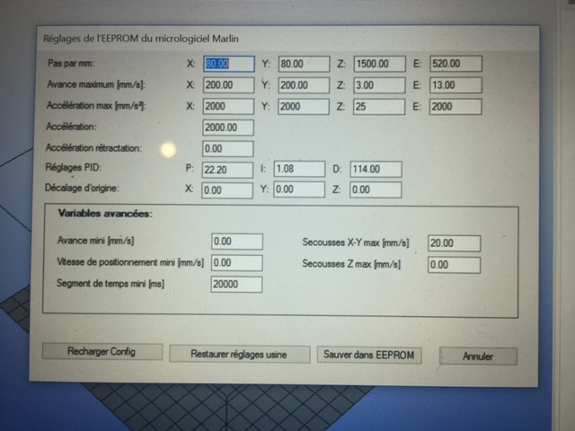
J'ai jeté un coup d'oeil au Marlin/configuration.h et c'est bizarre parce les valeurs du marlin ne correspondent pas à ce que m'indique Repetier !
Extrait du fichier Marlin :
/ default settings
#define DEFAULT_AXIS_STEPS_PER_UNIT {80,80,4000,520} // default steps per unit for Ultimaker
#define DEFAULT_MAX_FEEDRATE {500, 500, 2, 13} // (mm/sec)
Alors que Repetier m'indique 80,80,1500,520 ! (cf copie écran).
Bizarre tout cela, il faut que j'étudie en profondeur le wiki Marlin !
Edited 1 time(s). Last edit at 08/30/2016 08:46AM by bertrandp.
|
Re: Prusa i3 Pb calibration Z August 30, 2016 09:19AM |
Registered: 9 years ago Posts: 148 |
Les valeurs du configuration.h sont les valeurs "par defaut" qui sont inscrite dans l'eeprom lors du 1er lancement (ou si l'eeprom est vide), Repetier ne modifie pas ce fichier, mais directement l'eeprom.
Si tu veux retrouver les valeurs du configuration.h dans l'eeprom, il faut lancer un M502 (Revert to the default "factory settings.")
Si tu veux retrouver les valeurs du configuration.h dans l'eeprom, il faut lancer un M502 (Revert to the default "factory settings.")
|
Re: Prusa i3 Pb calibration Z August 30, 2016 09:30AM |
Registered: 7 years ago Posts: 24 |

|
Re: Prusa i3 Pb calibration Z August 30, 2016 10:15AM |
Registered: 9 years ago Posts: 148 |
|
Re: Prusa i3 Pb calibration Z August 30, 2016 10:21AM |
Registered: 9 years ago Posts: 148 |
Un truc par contre me chiffonne:
Si je ne dis pas de bêtise, dans la théorie il ne faut jamais imprimer un hauteur de couche (layer height) supérieure au diamètre de sa buse.
Du coup, si tu reprends tes 4285 mais que tu règles lors du tranchage a une hauteur de couche de 0.2mm?
PS : pour vérifier tes 4285 tu n'es pas obligé de lancer une impression. Demande juste une montée manuelle du Z de 50mm et mesure qu'elle est bien montée d'autant.
Quote
Achat donc d'un Extrudeur Hexagon 1,75mm/0,4mm
Quote
Ensuite j'ai tenté l'impression du cube (layer height) 0,5 mm ci-après
Si je ne dis pas de bêtise, dans la théorie il ne faut jamais imprimer un hauteur de couche (layer height) supérieure au diamètre de sa buse.
Du coup, si tu reprends tes 4285 mais que tu règles lors du tranchage a une hauteur de couche de 0.2mm?
PS : pour vérifier tes 4285 tu n'es pas obligé de lancer une impression. Demande juste une montée manuelle du Z de 50mm et mesure qu'elle est bien montée d'autant.
|
Re: Prusa i3 Pb calibration Z August 30, 2016 10:34AM |
Registered: 7 years ago Posts: 24 |
|
Re: Prusa i3 Pb calibration Z August 30, 2016 10:47AM |
Registered: 9 years ago Posts: 543 |
|
Re: Prusa i3 Pb calibration Z August 30, 2016 04:48PM |
Registered: 8 years ago Posts: 489 |
En faite, si tu changes directement les valeurs de l'eeprom et que tu fais un reset, tu vas te retrouver avec les valeurs par défaut de ton firmware.
Ta solution est pratique et rapide pour tester différentes choses, mais à partir du moment ou tu es certain de tes valeurs, le mieux est de modifier directement le firmware.
Ma Prusa i3 (ancienne imprimante, transformé en Itopie depuis)
Mon Itopie
Mon thingiverse
[TUTO] Lcd full graphic avec firmware Marlin
--
Possibilité de vous imprimer des pièces, n'hésitez pas à demander en MP
|
Re: Prusa i3 Pb calibration Z August 31, 2016 03:39AM |
Registered: 7 years ago Posts: 24 |
Quote
Grim
Si je ne dis pas de bêtise, dans la théorie il ne faut jamais imprimer un hauteur de couche (layer height) supérieure au diamètre de sa buse.
Du coup, si tu reprends tes 4285 mais que tu règles lors du tranchage a une hauteur de couche de 0.2mm?
PS : pour vérifier tes 4285 tu n'es pas obligé de lancer une impression. Demande juste une montée manuelle du Z de 50mm et mesure qu'elle est bien montée d'autant.
Voilà le problème venait des paramètres Slic3r, la hauteur de couche à 0,4 mm par défaut n'était pas bonne.
Comme un newbie, je ne m'étais pas encore intéressée au paramétrage de Slic3r et je constate que cela à son importance.
Les dimensions sont OK, par contre je trouve qu'il manque un petit peu de matière sur cette pièce de calibrage.
En effet, je constate sur certaine couche des petits trous sur le pourtour de la pièce....encore un paramétrage de Slic3r à découvrir
Edited 1 time(s). Last edit at 08/31/2016 03:44AM by bertrandp.
|
Re: Prusa i3 Pb calibration Z August 31, 2016 09:14AM |
Registered: 7 years ago Posts: 24 |
J'ai bien compris que l'on ne devait pas dépasser 80% de la taille de buse pour le paramètre Layer Height, soit dans mon cas 0.4x0.8=0.32
J'ai mis 0.2 comme valeur, quelle incidence au lieu de 0.32 ? la hauteur de ma pièce est correcte
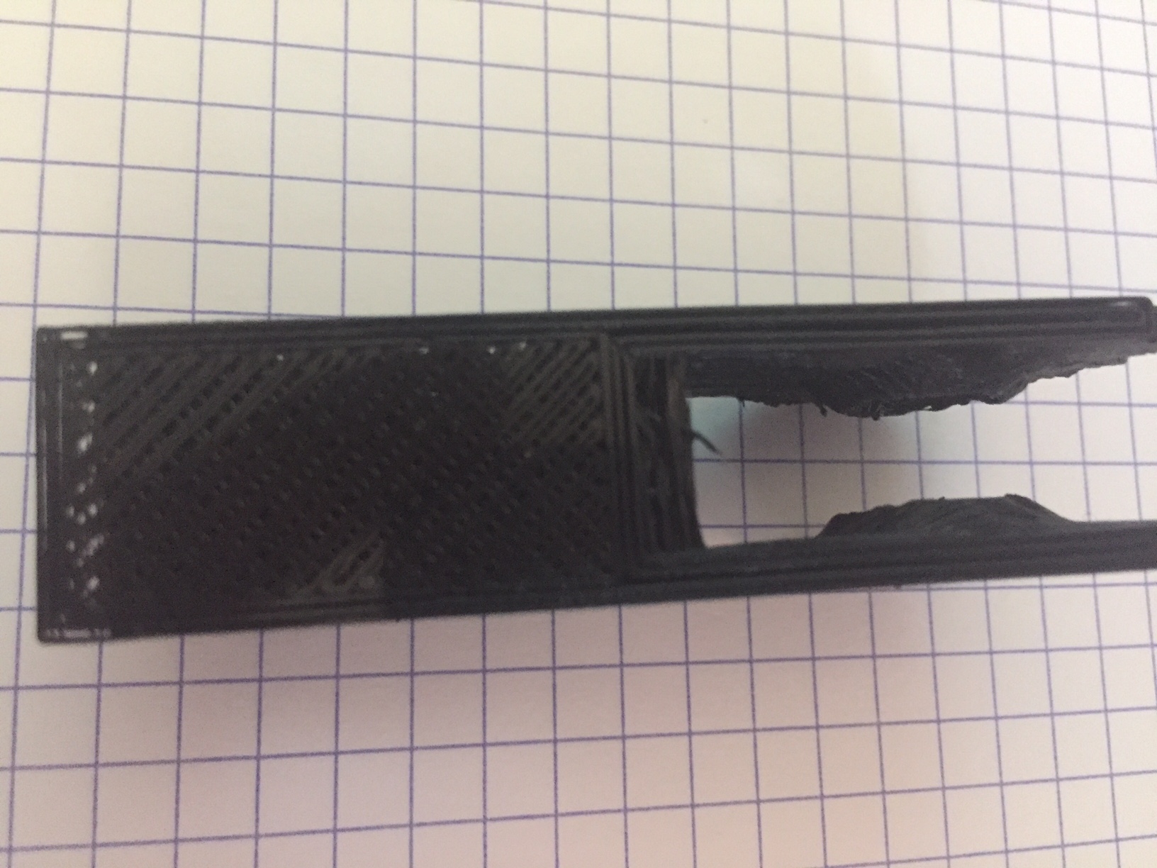
J'ai tenté une impression d'un Y Idler, pour voir....
Conclusion :
1/ je penses que ma courroie en Y n'est pas assez tendue et il y a du avoir des sauts de courroie sur la poulie (car contrairement aux pièces de calibrage, cette pièce demande des actions très rapides de la machine).
2/ remplissage pas assez conséquent de matière, là aussi il faut que je regarde d'ou cela peut venir dans Slic3R
Bon j'ai encore un sacré travail de paramétrage...
J'ai mis 0.2 comme valeur, quelle incidence au lieu de 0.32 ? la hauteur de ma pièce est correcte
J'ai tenté une impression d'un Y Idler, pour voir....
Conclusion :
1/ je penses que ma courroie en Y n'est pas assez tendue et il y a du avoir des sauts de courroie sur la poulie (car contrairement aux pièces de calibrage, cette pièce demande des actions très rapides de la machine).
2/ remplissage pas assez conséquent de matière, là aussi il faut que je regarde d'ou cela peut venir dans Slic3R
Bon j'ai encore un sacré travail de paramétrage...
|
Re: Prusa i3 Pb calibration Z August 31, 2016 10:13AM |
Registered: 9 years ago Posts: 148 |
Quote
bertrandp
J'ai bien compris que l'on ne devait pas dépasser 80% de la taille de buse pour le paramètre Layer Height, soit dans mon cas 0.4x0.8=0.32
J'ai mis 0.2 comme valeur, quelle incidence au lieu de 0.32 ? la hauteur de ma pièce est correcte
Pour un pièce de 10mm de hauteur, tu auras 10/0.2=50 couches ou 10/0.32=31,25 couches (du coup 31 ou 32 je suis pas sur, donc trop ou pas assez haute)
Pour les réglages Slic3r, je ne l'ai que très peu utiliser je suis donc pas la plus a même de t'aider a ce niveau la

Pour les sauts de courroie sur Y, tu peux essayer de réduire la vitesse d'impression le temps que tu imprime ton idler du mieux possible, je présume que c'est lui qui te servira a mieux la tendre
Pour le remplissage, il y a surement dans Slic3r un coefficient d'extrusion (qui doit être a 100 (%?) ou a 1 par défaut, essaye 110(%?) ou 1,1)
|
Re: Prusa i3 Pb calibration Z September 01, 2016 03:29AM |
Registered: 9 years ago Posts: 49 |
Bonjour
Pas facile de suivre et de faire des recoupement d'infos ^^
[www.lesimprimantes3d.fr]
@+
Un problème ? Channel IRC reprap en francais ! ( Bons plans, soluces, aide, partage ... .)
Pas facile de suivre et de faire des recoupement d'infos ^^
[www.lesimprimantes3d.fr]
@+
Un problème ? Channel IRC reprap en francais ! ( Bons plans, soluces, aide, partage ... .)
|
Re: Prusa i3 Pb calibration Z September 05, 2016 04:34AM |
Registered: 7 years ago Posts: 24 |
Pour vous tenir informé de mon avancé.
Ce week end, j'ai redémonté mon imprimante et fais les actions suivantes :
1/ changement des tiges filetées en Z (celles que j'avais récupéré me paraissaient légèrement voilés
2/ polissage des tiges lisses (non chromés) avec du Belgom Alu
Et bien la qualité des pièces est au rendez vous.
Je penses que maintenant c'est plus du paramétrage dans Slic3R
|
Re: Prusa i3 Pb calibration Z September 05, 2016 05:44AM |
Registered: 8 years ago Posts: 489 |
Bonne nouvelle 
Ma Prusa i3 (ancienne imprimante, transformé en Itopie depuis)
Mon Itopie
Mon thingiverse
[TUTO] Lcd full graphic avec firmware Marlin
--
Possibilité de vous imprimer des pièces, n'hésitez pas à demander en MP
Ma Prusa i3 (ancienne imprimante, transformé en Itopie depuis)
Mon Itopie
Mon thingiverse
[TUTO] Lcd full graphic avec firmware Marlin
--
Possibilité de vous imprimer des pièces, n'hésitez pas à demander en MP
Sorry, only registered users may post in this forum.