Duet : Implementation of square delta ?
Posted by PRZ
|
Duet : Implementation of square delta ? August 05, 2015 05:27PM |
Registered: 8 years ago Posts: 475 |
A few month ago, Ryan Carlyle have shown a delta with three columns at angles of 90°, the 'square delta'.
[www.youtube.com]
Thread about it (on google Deltabot forum):
[groups.google.com]
While this setup slightly lower the effector stability, there are many constructive advantages in it.
Ryan is using a Smoothieboard as controller.
I am interested to build a printer with the same geometry (but different construction, in short, a wood box with carriage running on steel angles), using the Duet, as I am now using it happily on the Fisher.
Will it be possible to run this geometry in the duet, including the calibration ?
I had a very quick look at the code, but I don't see well how delta geometry is implemented.
Calibration use matrix transformation.
I have implemented this geometry in the OpenSCAD delta simulator and that was fairly quick, but the simulator did'nt need calibration...
[github.com]
|
Re: Duet : Implementation of square delta ? August 05, 2015 05:49PM |
Registered: 10 years ago Posts: 14,672 |
If the diagonal rods of the square delta are all the same length, then the firmware should already handle that geometry. To describe it in config.g, call the two opposite towers X and Y, and enter angular offsets of +30 degrees for Y and -30 degrees for X in the M665 command. The X axis of the machine will be the line between the X and Y towers.
Large delta printer [miscsolutions.wordpress.com], E3D tool changer, Robotdigg SCARA printer, Crane Quad and Ormerod
Disclosure: I design Duet electronics and work on RepRapFirmware, [duet3d.com].
Large delta printer [miscsolutions.wordpress.com], E3D tool changer, Robotdigg SCARA printer, Crane Quad and Ormerod
Disclosure: I design Duet electronics and work on RepRapFirmware, [duet3d.com].
|
Re: Duet : Implementation of square delta ? August 05, 2015 06:21PM |
Registered: 8 years ago Posts: 475 |
|
Re: Duet : Implementation of square delta ? August 05, 2015 07:11PM |
Registered: 10 years ago Posts: 14,672 |
Quote
PRZ
David, thanks !
Yes rod length are identical.
Thats is really excellent, I will try
No problem with the calibration routine ?
The calibration routine should still work as before. It uses the actual geometry to compute the effect of changing things.
btw in firmware 1.09e I am adding an optional Z tower angular offset as well. This will allow you to use the same tower offsets that Ryan described (15, -15 and 45 degrees), so that the XY print axes will be parallel to the edges of the bed instead of at 45 degrees to them.
Large delta printer [miscsolutions.wordpress.com], E3D tool changer, Robotdigg SCARA printer, Crane Quad and Ormerod
Disclosure: I design Duet electronics and work on RepRapFirmware, [duet3d.com].
|
Re: Duet : Implementation of square delta ? August 05, 2015 11:50PM |
Registered: 8 years ago Posts: 155 |
|
Re: Duet : Implementation of square delta ? August 06, 2015 02:43AM |
Registered: 10 years ago Posts: 14,672 |
Quote
lolocaledo
Hello,
I've just received my 2 Duet board. Where can I find information to set it up from scratch ?
Best regards,
Start at [reprap.org] which includes the wiring diagram for everything except the Z probe (however, in common with other electronics, if you have dual Z motors then it is usually better to connect them in series instead of in parallel although it depends on your motors). Here [reprappro.com] is another wiring diagram. If your Z probe is a switch, connect it to the E0 endstop pins instead.
The Resources section near the bottom of that Wiki page has links to other useful pages, in particular the RepRapPro pages explain how to update the firmware and do initial commissioning.
For firmware configuration, see the Links section at the end of [reprap.org].
Large delta printer [miscsolutions.wordpress.com], E3D tool changer, Robotdigg SCARA printer, Crane Quad and Ormerod
Disclosure: I design Duet electronics and work on RepRapFirmware, [duet3d.com].
|
Re: Duet : Implementation of square delta ? August 06, 2015 07:47AM |
Registered: 8 years ago Posts: 155 |
|
Re: Duet : Implementation of square delta ? August 06, 2015 09:07AM |
Registered: 10 years ago Posts: 14,672 |
Quote
lolocaledo
Hello,
Thank you DC42 for these informations.
I'm waiting for the PanelDue and sensors I ordered to you. Not received yet.
I want to use Duet and PanelDue on Delta Printer that is under construction.
I think I have first to upgrade to you DC42 firmware for Duet ?
Best regards,
I've sent you a PM regarding the tracking status or your order for reasons of data protection. Yes you currently need my fork of the firmware fork to run a delta - even RepRapPro uses my fork for their Fisher delta instead of their own.
Large delta printer [miscsolutions.wordpress.com], E3D tool changer, Robotdigg SCARA printer, Crane Quad and Ormerod
Disclosure: I design Duet electronics and work on RepRapFirmware, [duet3d.com].
|
Re: Duet : Implementation of square delta ? October 04, 2015 12:34PM |
Registered: 8 years ago Posts: 475 |
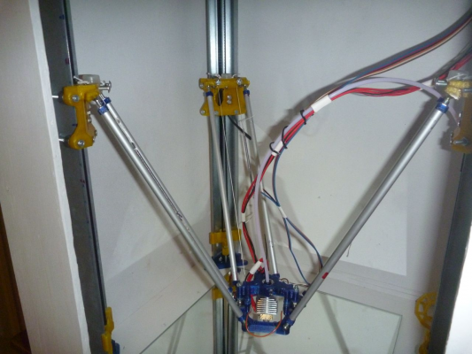
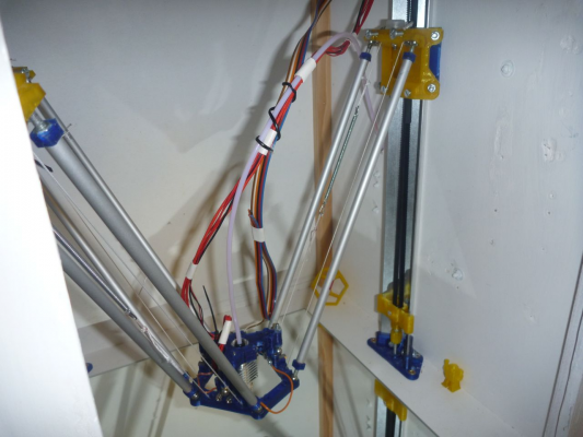
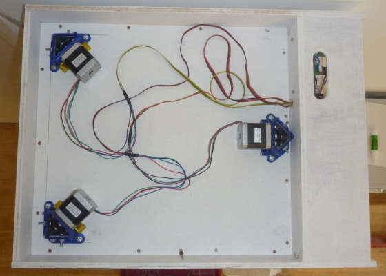
Here we are, my new printer 'D-Box' is running and the great news is unequal angle delta works on the Duet!
In fact, following comments from Ryan Carlyle, I did not implemented square delta, but I set the third column at the middle of the panel, so my angles are 135, 90, 135, and the parameters are :
In fact, as I have positioned the columns with templates, I could (and should, indeed) have set the angles with lesser differences. More on that later.
The calibration 4 parameters, 7 point done on the box bottom gives differences of 0.12mm and 0.24mm with ten points. Further tests on a mirror show only minor improvement.
Printed 100mm calibration angle have difference of 0.2mm between X and Y
I have tested calibration with 6 parameters and ten points, and it gives angles X 15.2° and Y -16° (stable after a few runs). This is unrealistic as that is a positioning error of 4mm, but I entered it in the M665, which gives a calibration difference of 0.05.
I then printed the same calibration angle. It gives a difference between X and Y of 1.3 mm. So the calibration 6 points find a geometry which minimize the calibration difference, so an easy first layer, but this geometry is not realistic and drive to part accuracy problems. I will do the same on the Fisher as I also have X/Y excessive differences and 6 parameters angles which also looks larger than the construction error allows.
I will print the delta calibration circle whan I will get a buildtak, as printing directly on the bottom of the box (or on a mirror) does not work for all parts, and especially not for this calibration part (in PETG). The machine is not completely finished and I did not have installed yet a part cooling fan and duct so I will not print PLA.
Note that I will make another topic for the printer, so please wait for general questions on the machine.
Edited 2 time(s). Last edit at 10/04/2015 01:05PM by PRZ.
In fact, following comments from Ryan Carlyle, I did not implemented square delta, but I set the third column at the middle of the panel, so my angles are 135, 90, 135, and the parameters are :
M665 X15 Y-15 ; Z column is the right column
In fact, as I have positioned the columns with templates, I could (and should, indeed) have set the angles with lesser differences. More on that later.
The calibration 4 parameters, 7 point done on the box bottom gives differences of 0.12mm and 0.24mm with ten points. Further tests on a mirror show only minor improvement.
Printed 100mm calibration angle have difference of 0.2mm between X and Y
I have tested calibration with 6 parameters and ten points, and it gives angles X 15.2° and Y -16° (stable after a few runs). This is unrealistic as that is a positioning error of 4mm, but I entered it in the M665, which gives a calibration difference of 0.05.
I then printed the same calibration angle. It gives a difference between X and Y of 1.3 mm. So the calibration 6 points find a geometry which minimize the calibration difference, so an easy first layer, but this geometry is not realistic and drive to part accuracy problems. I will do the same on the Fisher as I also have X/Y excessive differences and 6 parameters angles which also looks larger than the construction error allows.
I will print the delta calibration circle whan I will get a buildtak, as printing directly on the bottom of the box (or on a mirror) does not work for all parts, and especially not for this calibration part (in PETG). The machine is not completely finished and I did not have installed yet a part cooling fan and duct so I will not print PLA.
Note that I will make another topic for the printer, so please wait for general questions on the machine.
Edited 2 time(s). Last edit at 10/04/2015 01:05PM by PRZ.
|
Re: Duet : Implementation of square delta ? October 04, 2015 01:38PM |
Registered: 10 years ago Posts: 14,672 |
I'm glad the geometry is working. If the angles found by auto calibration are significantly different from the actual angles, that suggests to me that you have a significant build error somewhere, such as:
- Towers not perpendicular to bed in both directions
- Bed not flat
- Diagonal rods not all the same length
- Diagonal rod bearing spacing not the same at the top and bottom ends of a pair
- Rod ends not rotating smoothly in their sockets, but slipping sideways as well.
Large delta printer [miscsolutions.wordpress.com], E3D tool changer, Robotdigg SCARA printer, Crane Quad and Ormerod
Disclosure: I design Duet electronics and work on RepRapFirmware, [duet3d.com].
|
Re: Duet : Implementation of square delta ? October 04, 2015 02:30PM |
Registered: 8 years ago Posts: 475 |
It iis a box, so that geometry checking is much easier than for other delta
Towers are perpendicular. The angles from theory are within 0.25, . There is a slight error on x top support, may be 14.8 instead of 15°
My bed is not super flat, this is a wood panel. If testing with a mirror layed on the wood, The error is not much different, but as I use 3mm thick mirror which are quite flexible, they may fold and follow the wood plank.
Rod length are within 0.1mm
The biggest source of error is the effector, as I made the mistake to print it without compensating the X/Y error of the Fisher.
That may drive to a difference between space of the rods at each end of 0.5 mm. Not worse than the Fisher, but the rods are double length (314mm vs 160 mm).
Also, that may create an angle difference between the tower position and the effector angle of 0.3/0.4°.
I have quite significant friction in the rod ends, that I reduced with lubrication. I think use will improve that as the cup will adapt to the sphere. I may reduce the spring tension, as it don't need to be that much tight. They rotate in quite tight cups, so there is no sideway slipping. That may be a bigger source of error than the geometry.
What surprise me in fact is that I find the result of calibration with 4 parameters not that bad (on a mirror, deviation is 0.2 mm on ten points), but the modification done by the 6 parameters calibration are really important. I think the best way to calculate the angle deviation is to print a calibration part and reintroduce the result in M665.
For a large printer (usable diameter is 286mm), it is quite difficult to got a flat bed.
I have aluminium plates that I will test, they may be more stiff than a mirror.
Sorry, only registered users may post in this forum.


