Firmware to drive X-Y galvanometer
Posted by rskelton
|
Firmware to drive X-Y galvanometer April 06, 2013 02:17AM |
Registered: 14 years ago Posts: 8 |
Hi all,
I'm working on an SLA printer, using a laser diode instead of the DLP method that many are using for UV-curable resins. I'd ideally like to use an X-Y laser galvanometer for the setup, instead of putting the laser on a movable platform. With the correct optics, I can get dot sizes near the diffraction limit - even quadrupling that gives a dot size of around .05mm, and that will take ages to print with a mechanical bed, especially with a z-layer height of a similar size.
Long story short - I'm a mechanical design engineer, and while I have a bit of background in electronics and coding, I am far more versed in the mechanical side of things. Standard laser galvos need to be driven by an analog signal, and most scanners I have found have controllers for this, but they accept input in ILDA/laser show formats, which I have no idea how to deal with. Essentially, g-code is vectors with speed information, so I am curious if there is either a way to drive laser scanners with an arduino/similar microcontroller, or convert g-code into a format that the existing scanner drivers can use?
The other option I would have is to use a delta bot (rostock, cerberus, or one of those derivatives) since the laser diode itself is lightweight and delta bots tend to be much faster than a standard cartesian bot if they aren't too heavy. In this case, I wouldn't have the faintest clue where to start when trying to separate the Z commands out of the delta bot movements, and transfer those movements to a bed raising system.
Any ideas? Thanks!
|
Re: Firmware to drive X-Y galvanometer April 06, 2013 09:32AM |
Registered: 12 years ago Posts: 1,236 |
I'm not so familiar with SLA, so you will have to explain a few things. How long does the laser need to be in the same spot, ie. what is the cure time?
Galvos are used in laser shows because they need to repeat the same path rapidly to exploit POV. Typically the speed is 20Kpps or higher which means a dot time of less than 50us. I think that is way to short for SLA. You could hold the frame for a few seconds to build exposure, but that would seem to be inefficient, because the beam is being moved unnecessarily. Additionally, for laser shows, we are not to worried about precision, it is for art not engineering. I think it would be difficult to get high accuracy. Galvos are also expensive and complicated to drive.
SLA would seem to have the opposite requirement, you want relatively slow moving beam at high accuracy. That is effectively how laser engraver/cutters work. The mirrors are moved on a conventional X-Y gantry driven by stepper motors.
The ILDA format is essentially a vector drawing format, but does not contain any specification for speed. So converting the GCode vectors is relatively easy, but I don't know how you would control the timing.
Delta bots would seem like a good way to go, but again it depends on what the cure time is. Conventional X-Y bots can actually go pretty fast, they are limited by the mass of the extruder and then the extrusion rate, which is a lot lower. Personally I would start with an X-Y bot since they are simple and well known, when the laser system is proved out then look to enhance the X-Y system.
|
Re: Firmware to drive X-Y galvanometer April 06, 2013 03:20PM |
Registered: 14 years ago Posts: 8 |
Here's a good (real time) video of the SLA process.
The laser moves quite fast in comparison with even the fastest delta or cartesian bots. Energy levels for cure are usually around 500 to 3000 mJ/cm^2, depending on wavelength and specifics of the resin - with a spot size of 0.05 mm, that gives an area of 2x10^-5 cm^2, so a 400 mW output laser needs about 0.1 milliseconds over the area to cure (at that rate, it is 2000 mJ/cm^2 energy density).
Granted, I can turn down the laser power if I'm going with a mechanical build, or increase the spot size, but running a galvo would end up with quicker builds, and potentially higher accuracy since they have position feedback.
Speed would be controlled likely by limiting the scan rate of the galvos. Find the travel time for the X or Y mirrors to scan a full length of the build platform, slow it down so time over any specific point is ideal for curing at the current laser power level.
The other issue is beam focusing (if I was running a galvo). However, that's generally solved by a very expensive f-theta lens, or a controlled movable focus lens (fast linear actuator or piezo stack) that is hardcoded to positions based on the angle from the normal of the build platform. F-theta lenses are anywhere from about $750 to $10k, so that's probably out. Pulling a lens from a photo enlarger might work as well, they are close to flat-field focus, with a small enough deviation to be acceptable.
|
Re: Firmware to drive X-Y galvanometer April 06, 2013 04:08PM |
Registered: 12 years ago Posts: 1,236 |
Ok, the cure time per spot is a LOT faster than I was thinking! I can see why galvos would be preferred.
I came across this page which looks pretty interesting [elm-chan.org]. He is using 12 bit DAC (4096 points), I am not sure what effective resolution he gets from the overall system. He's got a lot of bespoke electronics in there.
" It will not needed to explain each function of the controller board and its firmware because you must have a skill to design a laser display controller if you are going to build galvos."

Do you have any off the shelf galvos in mind? It would be useful to get some specs to see what is needed to drive them. I found this on ebay, [www.ebay.co.uk] it is just about within my budget for "playing around with".
I came across this page which looks pretty interesting [elm-chan.org]. He is using 12 bit DAC (4096 points), I am not sure what effective resolution he gets from the overall system. He's got a lot of bespoke electronics in there.
" It will not needed to explain each function of the controller board and its firmware because you must have a skill to design a laser display controller if you are going to build galvos."
Do you have any off the shelf galvos in mind? It would be useful to get some specs to see what is needed to drive them. I found this on ebay, [www.ebay.co.uk] it is just about within my budget for "playing around with".
|
Re: Firmware to drive X-Y galvanometer April 06, 2013 05:26PM |
Registered: 14 years ago Posts: 8 |
I've been looking at similar setups off of ebay as well. After some more digging, I found the ILDA specifications here (PDF link). The "show card" basically looks to be a card with various preprogrammed displays, as well as having breakouts for TTL laser control and interfaces to the galvanometer amplifiers.
The ILDA spec shows that four pins, +X, +Y, -X, and -Y could be used to get direct XY control over the galvos. They take a +/- 10v analog signal, and that's spit into the amplifiers on the galvos and translate to mirror movement. I guess where I'm lost is how to go from the standard reprap method of "send N pulses at frequency F to go distance A on the X axis at S speed" to "send analog voltage V with a ramp rate R from the previous voltage to go distance A on the X axis at S speed". I know I gotta go through a DAC, but that's where I get lost.
I'm also starting to maybe lean towards a super lightweight delta bot, since I have the experience and the equipment to make most, if not all the moving parts out of carbon fiber and CNC'd aluminum. It still would be slower, but it would be way less work, and arguably less expensive, than fiddling with moving optics and writing custom firmware.
|
Re: Firmware to drive X-Y galvanometer April 06, 2013 08:12PM |
Registered: 12 years ago Posts: 1,236 |
rskelton Wrote:
-------------------------------------------------------
> I've been looking at similar setups off of ebay as
> well. After some more digging, I found the ILDA
> specifications here (PDF link). The "show card"
> basically looks to be a card with various
> preprogrammed displays, as well as having
> breakouts for TTL laser control and interfaces to
> the galvanometer amplifiers.
Yep, I think I see how it all hangs together.
> The ILDA spec shows that four pins, +X, +Y, -X,
> and -Y could be used to get direct XY control over
> the galvos. They take a +/- 10v analog signal, and
> that's spit into the amplifiers on the galvos and
> translate to mirror movement.
Agreed, if we create bipolar signals to feed to each galvo controller, then that allows the most direct access. The ILDA standard goes to 16 bit resolution, I don't what sort of resolution is required here.
> I guess where I'm
> lost is how to go from the standard reprap method
> of "send N pulses at frequency F to go distance A
> on the X axis at S speed" to "send analog voltage
> V with a ramp rate R from the previous voltage to
> go distance A on the X axis at S speed". I know I
> gotta go through a DAC, but that's where I get
> lost.
For me, that is the easy bit Where regular Reprap would output a step pulse to a stepper, we can just increment (or decrement) the current position and output the new position to the DAC. Getting a clean +/-10V output may take a little electronics, not really my field but I can probably find that somewhere.
I think this is very doable. We are helped by the ILDA standard here.
> I'm also starting to maybe lean towards a super
> lightweight delta bot, since I have the experience
> and the equipment to make most, if not all the
> moving parts out of carbon fiber and CNC'd
> aluminum. It still would be slower, but it would
> be way less work, and arguably less expensive,
> than fiddling with moving optics and writing
> custom firmware.
I admit I didn't realise how fast the laser scanning is in SLA. Deltabot would work, but I think maybe too slow for high resolution?
Cost wise, galvos might cost $120 but saves two axes.
Either way, I would quite like to play with those galvos, even I just end up with a pretty light show! Would the setup be transferable to 400mW laser? I guess it might need different mirrors, I would probably use a lower power laser for testing it out.
-------------------------------------------------------
> I've been looking at similar setups off of ebay as
> well. After some more digging, I found the ILDA
> specifications here (PDF link). The "show card"
> basically looks to be a card with various
> preprogrammed displays, as well as having
> breakouts for TTL laser control and interfaces to
> the galvanometer amplifiers.
Yep, I think I see how it all hangs together.
> The ILDA spec shows that four pins, +X, +Y, -X,
> and -Y could be used to get direct XY control over
> the galvos. They take a +/- 10v analog signal, and
> that's spit into the amplifiers on the galvos and
> translate to mirror movement.
Agreed, if we create bipolar signals to feed to each galvo controller, then that allows the most direct access. The ILDA standard goes to 16 bit resolution, I don't what sort of resolution is required here.
> I guess where I'm
> lost is how to go from the standard reprap method
> of "send N pulses at frequency F to go distance A
> on the X axis at S speed" to "send analog voltage
> V with a ramp rate R from the previous voltage to
> go distance A on the X axis at S speed". I know I
> gotta go through a DAC, but that's where I get
> lost.
For me, that is the easy bit
Where regular Reprap would output a step pulse to a stepper, we can just increment (or decrement) the current position and output the new position to the DAC. Getting a clean +/-10V output may take a little electronics, not really my field but I can probably find that somewhere.I think this is very doable. We are helped by the ILDA standard here.
> I'm also starting to maybe lean towards a super
> lightweight delta bot, since I have the experience
> and the equipment to make most, if not all the
> moving parts out of carbon fiber and CNC'd
> aluminum. It still would be slower, but it would
> be way less work, and arguably less expensive,
> than fiddling with moving optics and writing
> custom firmware.
I admit I didn't realise how fast the laser scanning is in SLA. Deltabot would work, but I think maybe too slow for high resolution?
Cost wise, galvos might cost $120 but saves two axes.
Either way, I would quite like to play with those galvos, even I just end up with a pretty light show! Would the setup be transferable to 400mW laser? I guess it might need different mirrors, I would probably use a lower power laser for testing it out.
|
Re: Firmware to drive X-Y galvanometer April 06, 2013 09:20PM |
Registered: 14 years ago Posts: 8 |
Curse and/or bless you and your powers of coding! With regards to the laser power, galvos are usually made for laser shows, so they can generally handle whatever you can throw at them. A glass mirror needs a decent amount of power to reach it's damage threshold (though similar ranges as compared to UV curing). To get around this, you have the focal length of the laser be somewhat long, and the galvos set far away from the surface, or you run it through a lens afterwards, or both. Even cheap ebay galvos can withstand 1W lasers - damage is based much more on dot size than diode output.
As for swapping out mirrors, the cheapest type of mirror is an aluminum coated mirror, which just happens to be perfect for visible light and near-UV wavelength (around 400nm to 20um). So buying an ebay galvo would work well for this purpose. If you feel like dropping the cash and playing around with this, go for it - though using a cheap laser pointer would probably be good for testing. Half a watt of any laser source can fry your eyes real quick if it goes in the wrong place.
If you're curious where I got my lasers from, it's from this shop. They're gutted from Blu-ray burners, and placed into a heatsink housing with lenses and a driver.
I may build the delta-bot anyway, since my old prusa mendel could use an upgrade and I could use the delta-bot to prove out the laser system before dropping money on galvos and other bits. But I really think there's promise with a true SLA system - apart from the material cost, the machine cost is fairly low, and resolution is orders of magnitude better than FDM. Even using non-reprap parts such as leadscrews and linear guide rail extrusions. right now my (preliminary) BOM for this design consists of:
RAMPS board, plus DAC costs: $150, ultimachine
Arduino: $50ish
80/20, frame materials: $50-$75, 80/20
igus bearings/guide rails: $80, igus
Laser diode w/ collimating lens: $100
galvanometer: $120, ebay
Stepper motor: $15, phidgets
fasteners, thrust bearings, leadscrews, etc: $50-$100, mcmaster
build platform material: $50, aluminum, mcmaster
Build bed material: $30, borosilicate glass
Teflon/FEP adhesive sheet: $30, CS Hyde
photo enlarger lens: $30 (usually you can find these cheap and/or free from old enlargers)
So even considering that I'm not using reprapped parts, this still comes out to a build cost of about $800 - bump it up to $1000-$1200 for me, since I'm probably gonna fubar a few parts first and/or blow a diode or two.
If you end up getting a set of galvos and getting something working, let me know! I'm a bit broke right now, or I would consider donating/splitting the cost with you or something. Maybe in a week or so when I get another paycheck.
Thanks!
|
Re: Firmware to drive X-Y galvanometer April 08, 2013 06:16AM |
Admin Registered: 16 years ago Posts: 13,884 |
... I now have two comercial XY-galvo-heads with the electronics and will try to reactivate them or use them with my own drivers, so interested in this development too 
One of the setups is from an +20 years old 3DSystems SLA-printer - here I have all the 'guts' and the controller (but the HeCD-laser), but no information regarding the electronics ... have to solve it on my own or find some internal data sheets ...
The other one is an engraving/marking system from 2001 with a (maybe nonfunctional) 150Watt NdYAG-laser and a XY-scanner head with 250x250mm working area -- here I hope to get the information and maybe the controlling PC and software ...
Viktor
--------
Aufruf zum Projekt "Müll-freie Meere" - [reprap.org] -- Deutsche Facebook-Gruppe - [www.facebook.com]
Call for the project "garbage-free seas" - [reprap.org]
|
Re: Firmware to drive X-Y galvanometer April 08, 2013 11:46PM |
Registered: 14 years ago Posts: 8 |
Viktor,
Nice! Where did you happen upon that equpment? I'd be interested to see pictures of the scan head and any accompanying lenses... It's been a while since I've worked around a "professional" SLA machine, and at the time I didn't think to take pictures of the optics.
If you do get one of those systems working and reading g-code, you're 95% of the way there. 405 nm diodes are relatively cheap - I picked up one with some basic optics, 400 mW, and the diode driver, for $99 - shipped from the US so there weren't any customs issues. They gut them from blu-ray burners, and you can just get the laser sled with the diodes for around $40. It's fairly easy to machine an optics mount/alignment setup for a diode laser, or if you want to buy them, Thorlabs has parts for (relatively) cheap.
All you would need after that is a bed platform system. Stepper motor, some threaded rod or leadscrew, and a piece of borosilicate (pyrex) glass (standard soda-lime glass has crappy transmission in the UV spectrum) to use as a print bed. This link is a stick-on teflon coating so the cured resin sticks to the print bed, and not the glass.
My lasers have recently arrived, so I'm going to start building here in the next couple weeks hopefully, once I re-up my machine shop access at work. I tested the lasers with the bucktown polymers resin (I picked up some a few months ago when they still sold it in quarts) and it works great - not quite as fast as the video I posted earlier, but I was just kinda waving the laser at the resin while holding the laser with my hand, so focus was not ideal. Cure depth of around 0.1mm, and cured areas after about 2 seconds of wiggling the laser around.
|
Re: Firmware to drive X-Y galvanometer April 09, 2013 02:15AM |
Admin Registered: 16 years ago Posts: 13,884 |
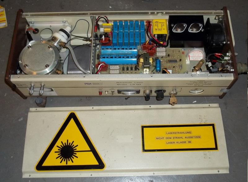
... I have several 'UV-printing' projects running, the easiest are with UV-modified DLP-beamers - here I'm modifying the beamers by replacing the original lamps by 405nm-LED's with 9Watts optical power and will make some tests with a N2-TAE-laser that emits 337nm with 200ps long pulses and peak powers of 400kW max ... attached images of the 405nm-LED's and the TAE-laser ...
The other images are the optical system of the old SLA-printer and the galvo-scannerhead of the marking laser .
I've received the parts as scrap or in exchange for some of my microtech tools, I developed some years ago ...
Edited 1 time(s). Last edit at 04/09/2013 02:16AM by VDX.
Viktor
--------
Aufruf zum Projekt "Müll-freie Meere" - [reprap.org] -- Deutsche Facebook-Gruppe - [www.facebook.com]
Call for the project "garbage-free seas" - [reprap.org]
|
Re: Firmware to drive X-Y galvanometer April 10, 2013 06:09PM |
Registered: 12 years ago Posts: 1,236 |
Ok, so I have ordered this kit from ebay [www.ebay.co.uk] I've also ordered some small laser modules for testing.
I've been looking around the web and found a few interesting things. The DIY laser show scheme is quite active, here is an Arduino shield [www.fab-favreau.com] specs are:
A standalone control with ARM CPU called LaserShark : [macpod.net] Notable features
I think either of those would be good platforms for initial development, just need some to port over a RepRap firmware which I think should be straightforward.
Also I found some SLA projects. [www.instructables.com] features a cartesian bot with a top mounted laser. There is an active Indiegogo project for a similar style but with bottom mounted laser called mUVe [www.indiegogo.com]. mUVe may have been posted elsewhere on RepRap already, I have had hardly been able to access RepRap for past few days. I am tempted to pledge to mUVe to help it along.
What I haven't seen, is a DIY SLA with a galvo scanner, so that could be a first? Though I usually find in RepRap someone already did it years ago... I am quite convinced the galvo idea is completely doable, and all the components are already available, it is just a question of integration and a bit of software. I think I can adapt my "old" Darwin printer to provide the mechanics.
Of course, there are some devilish details to sort out... do we absolutely need f-theta lens, if so, what type and how much $$? 12 bit DACS provide up to 4096 point resolution, will that be enough for our print area? (I am assuming 100mm x 100mm, initially)
I guess that galvo system designed for laser show will not be as accurate as we would like for SLA.
If we had higher resolution - 16 bit DACs or more, could we do the scanner correction in software, and avoid the need for f-theta lens?
I've been looking around the web and found a few interesting things. The DIY laser show scheme is quite active, here is an Arduino shield [www.fab-favreau.com] specs are:
Quote
Scan Rates: 1 kpps to 30 kpps
XY Resolution: 12 Bits
Color Resolution: 5 bits (for a total of 32,768 colors)
Colors: Red, Green, Blue outputs
TTL Shutter Output
A standalone control with ARM CPU called LaserShark : [macpod.net] Notable features
Quote
ILDA-standard differential +/-10V 12-bit X and Y output. Adjustable to get as close to the spec as possible.
2 0-5V single-ended 12-bit analog/ttl laser channels (Channel A and
1 5V single-ended ttl laser channel. (Channel C)*
Interlock connector (INTL)*
Without transfer optimizations the unit is able to drive all channels at full resolution up to 64Kpps. This rate could be increased by general optimizations to the transfer protocol or by reducing the number of output channels/resolution for custom applications.
LPC1343 Microcontroller running at 72Mhz.

I think either of those would be good platforms for initial development, just need some to port over a RepRap firmware which I think should be straightforward.
Also I found some SLA projects. [www.instructables.com] features a cartesian bot with a top mounted laser. There is an active Indiegogo project for a similar style but with bottom mounted laser called mUVe [www.indiegogo.com]. mUVe may have been posted elsewhere on RepRap already, I have had hardly been able to access RepRap for past few days. I am tempted to pledge to mUVe to help it along.
What I haven't seen, is a DIY SLA with a galvo scanner, so that could be a first? Though I usually find in RepRap someone already did it years ago...
I am quite convinced the galvo idea is completely doable, and all the components are already available, it is just a question of integration and a bit of software. I think I can adapt my "old" Darwin printer to provide the mechanics.Of course, there are some devilish details to sort out... do we absolutely need f-theta lens, if so, what type and how much $$? 12 bit DACS provide up to 4096 point resolution, will that be enough for our print area? (I am assuming 100mm x 100mm, initially)
I guess that galvo system designed for laser show will not be as accurate as we would like for SLA.
If we had higher resolution - 16 bit DACs or more, could we do the scanner correction in software, and avoid the need for f-theta lens?
|
Re: Firmware to drive X-Y galvanometer April 11, 2013 12:01AM |
Registered: 14 years ago Posts: 8 |
I think if we went with an enlarger lens, we could forgo the F-theta lens. Enlarger lenses are also a flat-field focus, it's simply that it would require software correction - the angle in vs. the angle out is not based on F*theta, it's based on F*tan(theta). Enlarger lenses are anywhere from free to $300-ish, instead of $750-$10k.
See here for more optics info on lenses, and lasers in general.
The Form-1 (from kickstarter fame) uses an X-Y galvo scanner, though the reason I'm thinking of going with a delta bot for proof-of-concept is also so I can get a larger build area (12"x12"x12" is what I'm planning).
See here for more optics info on lenses, and lasers in general.
The Form-1 (from kickstarter fame) uses an X-Y galvo scanner, though the reason I'm thinking of going with a delta bot for proof-of-concept is also so I can get a larger build area (12"x12"x12" is what I'm planning).
|
Re: Firmware to drive X-Y galvanometer April 11, 2013 04:28AM |
Registered: 12 years ago Posts: 1,236 |
|
Re: Firmware to drive X-Y galvanometer April 11, 2013 02:29PM |
Admin Registered: 16 years ago Posts: 13,884 |
... for a single scanning axis you can find cheap 'flatfield'-optics by salvaging old laserprinters - could be even simpler to use the faceted mirror-wheel instead of a galvo-scanner 
Viktor
--------
Aufruf zum Projekt "Müll-freie Meere" - [reprap.org] -- Deutsche Facebook-Gruppe - [www.facebook.com]
Call for the project "garbage-free seas" - [reprap.org]
Viktor
--------
Aufruf zum Projekt "Müll-freie Meere" - [reprap.org] -- Deutsche Facebook-Gruppe - [www.facebook.com]
Call for the project "garbage-free seas" - [reprap.org]
|
Re: Firmware to drive X-Y galvanometer April 13, 2013 06:09PM |
Registered: 12 years ago Posts: 1,236 |
Form-1 does not seem to be open source, but there is an animation on their website [formlabs.com] showing the galvo scanner. The diagram shows two mirrors, but no lens. I guess the diagram is a simplified view, but I was wondering if it was significant.
I've now received the galvo kit. The "show card" has DACs on board, but no serial interface apart from DMX. I have also ordered a LaserShark board, while I wait for that, I will see if I can do anything with the show card. I am still searching for suitable lenses that don't cost too much.
I've now received the galvo kit. The "show card" has DACs on board, but no serial interface apart from DMX. I have also ordered a LaserShark board, while I wait for that, I will see if I can do anything with the show card. I am still searching for suitable lenses that don't cost too much.
|
Re: Firmware to drive X-Y galvanometer April 15, 2013 03:23AM |
Admin Registered: 16 years ago Posts: 13,884 |
... I think the ceapest way would be to salvage an old laser-printer for the 'single-axis' F-theta optics in the printing head and use this for the Y-axis, while the complete head would be displaced for the X-axis.
For my parts - I've received another nearly identical NdYAG-marking laser, this time complete with the water cooling system and a rotating axis, but the PS throws an error ... could be as simple as exchanging the broken parts from one with the equal parts of the second, to bring it up again
Viktor
--------
Aufruf zum Projekt "Müll-freie Meere" - [reprap.org] -- Deutsche Facebook-Gruppe - [www.facebook.com]
Call for the project "garbage-free seas" - [reprap.org]
|
Re: Firmware to drive X-Y galvanometer April 15, 2013 05:49PM |
Registered: 12 years ago Posts: 1,236 |
I'll keep my eyes open for scrap printers, there are plenty on ebay but the cost of transport is far more than they are worth! There's a guy at work who knows where to get stuff, I will ask him
I quite like the idea of a hybrid system, I think it has a lot of potential. The scan area would be at least A4 presumably. It could be a good compromise between speed and cost.
If a raster image was created for each layer, then the scanner could sweep across in one pass per layer. Throwing around some ballpark numbers, if each layer took 10 seconds to scan, then a 100 mm high object would take about 3 hours at 100 micron layers. If we could scan a layer in 2 seconds, it would take about 30 mins at 100 microns, or 50 micron layers in 70 minutes.
|
Re: Firmware to drive X-Y galvanometer April 16, 2013 02:13AM |
Admin Registered: 16 years ago Posts: 13,884 |
... maybe another idea beside galvos ant F-theta optics - I have some high resoution and fast stepper drivers, that can rotate small mirrors nearly as fast and accurate as galvos.
The better (more precise) motors have 10000 steps per rev @200khz, the others have more resolution (51200 steps per rev @10MHz) but more 'elastic play' under load. This drivers+motors are common in high accuracy CNC applications and I'll source some 5-axis controllers with 1/256 microstepping @200kHz this summer for <500€
Instead of fixing the mirrors on the motor axes you can set them on spring loaded levers, that will be tilted by the motors with thin wires, wounded around the axes ... could enhance the angular resolution up to some 1/1000 degs! - so enough for scanning with high resolution ...
Two of this steppers armed with small mirrors can scan a collimated laser-beam similar to galvos on a concave mirror, that is placed above the scanner, to a target beneath.
AFAIK even common bath-mirrors could give a good focus plane, and should be precise enough to concentrate the laser energy on a spot <0.1mm ... better ones should give <30 microns
Viktor
--------
Aufruf zum Projekt "Müll-freie Meere" - [reprap.org] -- Deutsche Facebook-Gruppe - [www.facebook.com]
Call for the project "garbage-free seas" - [reprap.org]
|
Re: Firmware to drive X-Y galvanometer July 24, 2013 07:50PM |
hI, IM LOOKING FOR MAKING A 3D UV RESIN PRINTER TOO..
i SEE TAHT THE OPTION WITH GALVOS PERHAPS WILL BE BETTER AND FASTER THAT THE CARTESIAN SYSTEMS? BUT WHAT ABOUT THE SCANED AREA, IM THINKING ON A 1000X1000X1000MM, COULD PRINT ALL THIS AREA WITH THE GALVOS SYSTEM?? WHAT ABOUT THE DISTORSION.?
iM THINKING IN TRANSFORM A CHEAP CO2 LASER (CHINESE) MACHINE..IT HAS A SIMPLY CARTESIAN SYSTEM AN UP AND DOWN PLATFORM.....IT SEE THAT PERHPS CAN MOVE AROUND 5000MM/M
wHAT DO YOU THINK AROUND?
FINALLY ANYBODY TRY THE GALVO SYSTEM?
BEST REGRADS AND THANKS FOR ALL
FERNANDO
|
Re: Firmware to drive X-Y galvanometer July 25, 2013 02:59AM |
Registered: 14 years ago Posts: 3,742 |
@FERNANDO: Is your SHIFT key stuck? 
Bob Morrison
Wörth am Rhein, Germany
"Luke, use the source!"
BLOG - PHOTOS - Thingiverse
Bob Morrison
Wörth am Rhein, Germany
"Luke, use the source!"
BLOG - PHOTOS - Thingiverse
|
Re: Firmware to drive X-Y galvanometer July 25, 2013 05:28AM |
Hi Bob.
Please, excuse me, anythin wrong last nigth with the shift key or on my mind!!!!!
I resend the post adequately.
Hi pleople, as i tell you on my other .....im looking for start my sla printer, but have a lot of dudes..
i see that the galvos option, will be faster and perhaps could have much resolution than a single cartesian system, but i dont know if the galvo system could scan a good area from about 1m x1m, to cover this so great area will cause a distortion of the laser, given its inclination at the ends.???
Other option is a simply carteisan system by transforming a cheap co2 laser machine that have an up an dow platform too, it can be runing of about 5000mm/s max ..
If anybody can help me will be apreciate.
Dont konow if Kelton finally try the galvos or not..
Thanks at all and excuse my last post and my bud english...
Regards
Fernando
Please, excuse me, anythin wrong last nigth with the shift key or on my mind!!!!!
I resend the post adequately.
Hi pleople, as i tell you on my other
.....im looking for start my sla printer, but have a lot of dudes..i see that the galvos option, will be faster and perhaps could have much resolution than a single cartesian system, but i dont know if the galvo system could scan a good area from about 1m x1m, to cover this so great area will cause a distortion of the laser, given its inclination at the ends.???
Other option is a simply carteisan system by transforming a cheap co2 laser machine that have an up an dow platform too, it can be runing of about 5000mm/s max ..
If anybody can help me will be apreciate.
Dont konow if Kelton finally try the galvos or not..
Thanks at all and excuse my last post
and my bud english...Regards
Fernando
|
Re: Firmware to drive X-Y galvanometer July 25, 2013 05:44AM |
Registered: 14 years ago Posts: 3,742 |
If you are lucky Viktor (VDX) can give you some information.
Bob Morrison
Wörth am Rhein, Germany
"Luke, use the source!"
BLOG - PHOTOS - Thingiverse
Bob Morrison
Wörth am Rhein, Germany
"Luke, use the source!"
BLOG - PHOTOS - Thingiverse
|
Re: Firmware to drive X-Y galvanometer July 25, 2013 04:32PM |
|
Re: Firmware to drive X-Y galvanometer August 14, 2013 03:18PM |
Admin Registered: 16 years ago Posts: 13,884 |
... the best comercial galvo-heads are only good for 250x250mm and then with a really expensive f-theta lens-head to define a sufficient focus plane.
The actually best methode is to fit a BluRay-diodehead on an old XY pen plotter (one where you can remove the bed) and replace the electronics with RepRap-style drivers and controller ...
Viktor
--------
Aufruf zum Projekt "Müll-freie Meere" - [reprap.org] -- Deutsche Facebook-Gruppe - [www.facebook.com]
Call for the project "garbage-free seas" - [reprap.org]
|
Re: Firmware to drive X-Y galvanometer February 27, 2014 03:57PM |
Admin Registered: 16 years ago Posts: 13,884 |
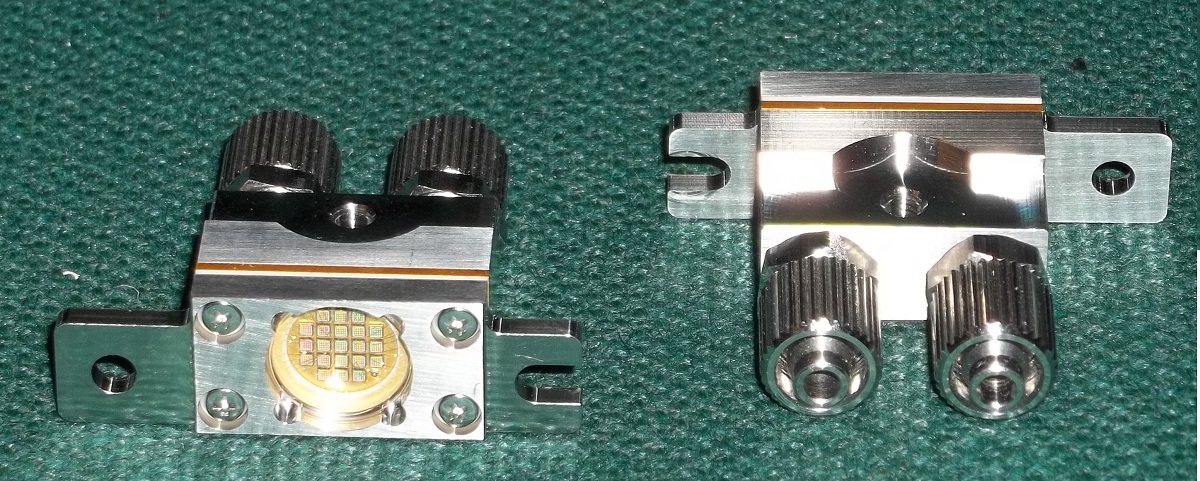
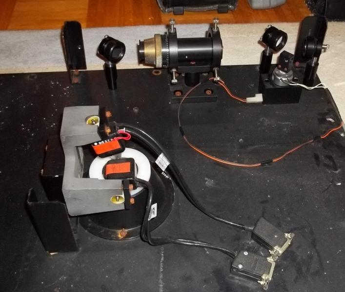
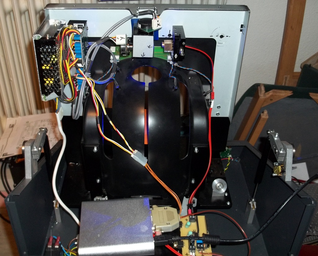
... I'm actually finishing the development of a XY-laserscanner -- based on an old dentalscanner, which I've completely disarmed, and then 'refurbished' with the parts and drivers for the XY-galvoscanner, drivers and power sources.
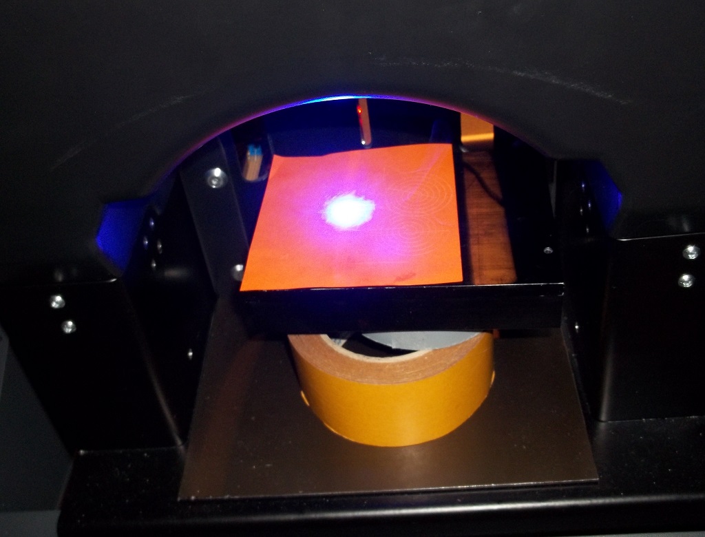
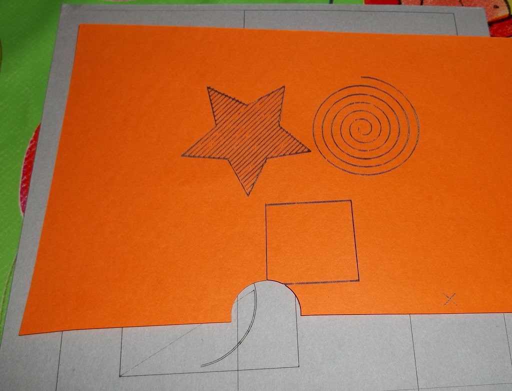
Attached are some images of the device without enclosure (and an image of an original dentalscanner) and some testing results with a 445nm-diode.
This diode is not meant to be used with the galvos (in this distances the spot is a line, not a dot!), only for visualising while developing.
In the next days I'll arm it with a fiber-laser, so it should be usefull to mark/engrave much more than paper
And here a video of the part in 'action' - [vimeo.com]
Viktor
--------
Aufruf zum Projekt "Müll-freie Meere" - [reprap.org] -- Deutsche Facebook-Gruppe - [www.facebook.com]
Call for the project "garbage-free seas" - [reprap.org]
|
Re: Firmware to drive X-Y galvanometer April 21, 2014 01:30AM |
Registered: 10 years ago Posts: 5 |
Hi, if I understand well we could use an enlarger lens instead of a ftheta, with a pre-distortion of slices to be projected ( or with some realtime triginometric calculation performed by a microprocessor driving a galvo via a d/a converter). This leads to a question: what focal do we need to scan, say, a 300x300 mm area? As I understand, the more you approach external borders the bigger distortion you have. Would a 105 mm enlarger lens be enough ?
|
Re: Firmware to drive X-Y galvanometer April 21, 2014 04:29PM |
Admin Registered: 16 years ago Posts: 13,884 |
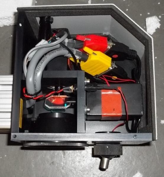
... with mirror-scanning adding optics and expanding the beam to diameters >5mm is a bit complex.
After cracking several mirrors with up to 15x15x1mm square-sizes, mounted on the cheapish galvo-scanners, I'm changing to 40x40x6mm big mirrors and servo-motors instead of the galvos for moving them.
With the smaller mirrors on the galvos the max. usable energy of the laser was around 10Watts in CW mode until they cracked or evaporated - with the 40x40mm mirrors I've managed to run above 50Watts in CW mode for some minutes without damaging the mirrors ... but heated the quartz-glass body to above 80degC!
With below 15Watts and fast scanning galvos I had to hit a spot on the target surface up to 30x to remove the material ... with the higher usable energy with the 40x40 mirrors this counts will be drastically reduced, so even with the slower servos (only around 1m/s engraving speed compared to above 20m/s with the galvos) I can mark/engrave fast enough ... and much faster than with my CNC-mill, what's engraving with max. 150mm/s.
Attached is an image of my last preassembled setup with the servo-motors and the drivers (bottom left), but without the controller ... wrecked it last week, so have to gather a new one
Viktor
--------
Aufruf zum Projekt "Müll-freie Meere" - [reprap.org] -- Deutsche Facebook-Gruppe - [www.facebook.com]
Call for the project "garbage-free seas" - [reprap.org]
After cracking several mirrors with up to 15x15x1mm square-sizes, mounted on the cheapish galvo-scanners, I'm changing to 40x40x6mm big mirrors and servo-motors instead of the galvos for moving them.
With the smaller mirrors on the galvos the max. usable energy of the laser was around 10Watts in CW mode until they cracked or evaporated - with the 40x40mm mirrors I've managed to run above 50Watts in CW mode for some minutes without damaging the mirrors ... but heated the quartz-glass body to above 80degC!
With below 15Watts and fast scanning galvos I had to hit a spot on the target surface up to 30x to remove the material ... with the higher usable energy with the 40x40 mirrors this counts will be drastically reduced, so even with the slower servos (only around 1m/s engraving speed compared to above 20m/s with the galvos) I can mark/engrave fast enough ... and much faster than with my CNC-mill, what's engraving with max. 150mm/s.
Attached is an image of my last preassembled setup with the servo-motors and the drivers (bottom left), but without the controller ... wrecked it last week, so have to gather a new one

Viktor
--------
Aufruf zum Projekt "Müll-freie Meere" - [reprap.org] -- Deutsche Facebook-Gruppe - [www.facebook.com]
Call for the project "garbage-free seas" - [reprap.org]
|
Re: Firmware to drive X-Y galvanometer May 15, 2014 06:13AM |
Admin Registered: 16 years ago Posts: 13,884 |
... got it moving with a reconfigured CNC-software (Editasc with 2 axes instead of 3-8 as common)!
Attached a video where I've tested it with 'moving focus' speeds of up to 200mm/s at the 'target' in around 200mm distance ... now I have to decise, which laser to insert ...
[vimeo.com]
Viktor
--------
Aufruf zum Projekt "Müll-freie Meere" - [reprap.org] -- Deutsche Facebook-Gruppe - [www.facebook.com]
Call for the project "garbage-free seas" - [reprap.org]
|
Re: Firmware to drive X-Y galvanometer May 16, 2014 04:34PM |
Admin Registered: 16 years ago Posts: 13,884 |
... first test with laser at 20 Watts, 100µs pulsing time on a black enamelled tile:
[vimeo.com]
Tested with 80 Watt and 200µs pulse-time (50% PWM ratio) ... the mirrors survived, but this was no duration test -- with 40 Watts CW they will degrade, so I have to find the max. PWM values with the 120Watt-laser ...
Viktor
--------
Aufruf zum Projekt "Müll-freie Meere" - [reprap.org] -- Deutsche Facebook-Gruppe - [www.facebook.com]
Call for the project "garbage-free seas" - [reprap.org]
|
Re: Firmware to drive X-Y galvanometer June 03, 2014 12:11AM |
Registered: 9 years ago Posts: 2 |
wao, so amazing Viktor.
what kind of laser source you use ? 80w @_@ are you use co2 tube?
now i'm used galvometer too, it not straight when two axis run together
what kind of laser source you use ? 80w @_@ are you use co2 tube?
now i'm used galvometer too, it not straight when two axis run together


Sorry, only registered users may post in this forum.