Reprap Arduino Due Shield project - looking for helping eyes.
Posted by sam0737
|
Re: Reprap Arduino Due Shield project - looking for helping eyes. May 04, 2013 01:39PM |
Registered: 12 years ago Posts: 1,236 |
STB Wrote:
-------------------------------------------------------
> Some thoughts on MOSFET switching. Gate drivers
> for the MOSFETS are mandatory, driving the gate
> with 3.3V results in bad Rds_on behaviour.
> You should think about driving the gates with 12V.
> MOSFETS in this case achieve significantly lower
> Rds_on and are cheaper compared to the 5V (logic)
> FETs.
Unfortunately, my electronics ability is such that I know a gate driver is a good idea, but not necessarily how to implement one cheaply and effectively.
There are many ways to implement a gate driver, do you have a particular circuit in mind?
|
Re: Reprap Arduino Due Shield project - looking for helping eyes. May 04, 2013 02:17PM |
Registered: 12 years ago Posts: 212 |
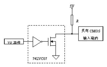
A SN7407D might be a solution. You can drive up to 6 MOSFETS.
Use 12V instead the 5V supply on the picture. A good value for R is 270 Ohms. Switching frequency in this case should be slow (hundreds of ms).
Edited 2 time(s). Last edit at 05/05/2013 03:57AM by STB.
Grüße / Regards
STB
______________________________________________________________
Basics about MOSFETs
|
Re: Reprap Arduino Due Shield project - looking for helping eyes. May 05, 2013 01:36AM |
Registered: 14 years ago Posts: 1,092 |
Regarding gate drivers:
IMO this depends on what FET is in use. I know I want to move away from the STP55NF06L's as they've never really been suitable for this job, are becoming harder to source, and are no longer significantly cheaper (in fact, they seem to be getting dearer).
This means we just need to choose decent FETs.
There are many FETs with very decent RDS(on) values when driven at 2.8v or less, and driving them at voltages higher than 5v provides little or no reduction in the RDS(on) value. The hard part will be choosing one that has reasonable max voltage that allows a suitable max voltage range. The IRLB8743PBF has a max voltage of 30V, which is quite suitable for a 24-28v supply into the board, a gate threshold of ~1.8v (max of 2.35v, so 3.3v is well over that), and has a nice low RDS(on) max of about 4.2mohms (@Vgs=4.5v, the smallest Vgs they measure the RDS(on) at).
My only concern will be just how much current we need to actually supply to drive the FET (which while small, is not zero, due to the inrush current to drive the gate capacitance), that might cause an issue for the Arduino Due. I personally don't think this is that much of an issue, though I'm happy to be proven wrong.
|
Re: Reprap Arduino Due Shield project - looking for helping eyes. May 05, 2013 03:49AM |
Admin Registered: 17 years ago Posts: 7,879 |
If you look at "Fig 12. On-Resistance vs. Gate Voltage" you will see why IRLB8743PBF is not suitable for 3.3V use. It needs a 5V gate driver as STB asserts. That also solves the gate capacitance problem. It is also why they state the max RDSon at 4.5V. You can design it into a 5V system and have some margin for the 5V rail being 5% low and some drop in the logic gate and still have a guaranteed RDSon figure.
I don't know if there are any MOSFETs that are fully enhanced at 3V. When switching just a few amps they can work fine but once you get into tens of amps I think a gate driver is always needed. It costs pennies and means you generate less heat, which makes the PCB design easier. Or it means you can use a cheaper MOSFET with higher RDSon and get an overall lower cost.
I usually include a small series resistor reduce the chance of parasitic oscillation and control the edge speed to meet EMC specs. There is no point in having very fast switching edges driving the bed when it takes seconds to respond. All it does is ring at the resonant frequency of the wiring, which will be in the VHF band. Since we are switching about 100W that can be a massive RF source.
[www.hydraraptor.blogspot.com]
|
Re: Reprap Arduino Due Shield project - looking for helping eyes. May 06, 2013 04:49AM |
Registered: 14 years ago Posts: 1,092 |
Fair call nophead.
That said, we could use a 5V gate drive circuit (there is 5V available off the Arduino Due header), rather than using 12V as STB suggested. IMO using 12V doesn't really buy us that much better performance, and with people using voltages like 18-19V and 24V much more often now, relying on 12V being available (without us specifically providing it - as it's not directly present on the Due) could be a problem. Providing drivers that can happily handle anything up to 30V could mean we spend more on driver circuitry than is really necessary. Yes it's a bit of a compromise, but it's a better compromise than we currently have in place on boards like RAMPS.
PS: Re: Cheaper FET's. I'm now seeing pricing for the IRLB8743PBF below the US $1 mark at various distributors for 1-5 off quantities, though places like e14 seem to be lagging this unless you buy in volume. I personally would prefer to see electronics with a semi-decent MOSFET as the primary option defined in the build instructions, mainly because cheap overseas volume-based knock-offs tend to use whatever the default build spec is. Admittedly, part of this is because I've seen so many people having issues with high current loads on things like the STP55NF06L's on the RAMPS boards. Even if driven with a 5v driver, the STP55NF06L's would still need to dissipate more heat compared to the IRLB8743PBF as the STP's RDS(on) is 5x the IRLB's (@Vgs=~5v).
|
Re: Reprap Arduino Due Shield project - looking for helping eyes. May 06, 2013 05:27AM |
Admin Registered: 17 years ago Posts: 7,879 |
12V into a logic drive MOSFET doesn't give you much but STBs point was you can use a non-logic drive MOSFET. They usually state RDSon at 10V so again suitable for 12V drive that is 10% low plus some margin. But as you say 12V isn't necessarily available and if PC PSUs are used without dummy load resistors it can easily be out of spec, so 5V is a much better bet.
e14 prices tend to have bigger markups for low volume compared to other similar companies. For example Mouser have much less steep price volume curves in general.
[www.hydraraptor.blogspot.com]
e14 prices tend to have bigger markups for low volume compared to other similar companies. For example Mouser have much less steep price volume curves in general.
[www.hydraraptor.blogspot.com]
|
Re: Reprap Arduino Due Shield project - looking for helping eyes. May 17, 2013 01:30PM |
Registered: 14 years ago Posts: 177 |
Looks like my thread has been hijacked LOL. But nevermind, it's all good info. Too busy with work, and I'm too lazy to check the forums...
I think the point of having fuse today is not preventing the IC from smoking, but the house from smoking.
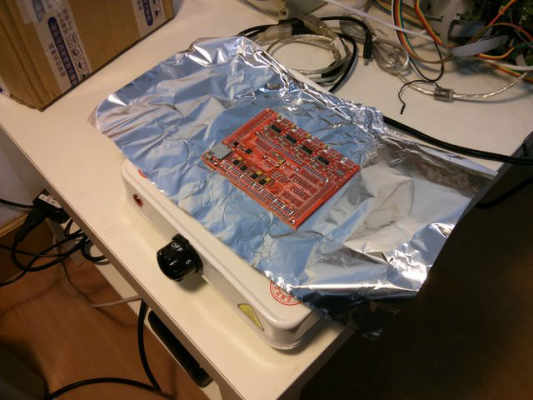
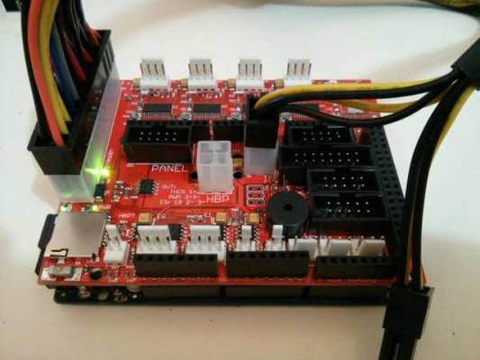
I got my board fabbed and soldered, a few minor bugs (mostly placement) but so far it's working.
It runs too hot (like I can't stick my finger to the backside of the PC if the stepper is set to run at 1.5A. I am getting some heatsink for that.
The HBP can handles 10A well though - large enough copper pour for the heatsink.
Currently I am working on writing a new firmware. I am porting ChibiOS/RT to Due (SAM3XA specifically) and writing firmware on top of it.
I get some basic working - Eclipse compilation. Drivers like USB, ADC, PWM, and Dual CDC over USB. (OS port: [github.com])
But at this speed, I guess it will take months for a firmware that achieve Marlin parity features.
PM me if someone want to join the development =)
Edited 1 time(s). Last edit at 05/17/2013 01:31PM by sam0737.
I think the point of having fuse today is not preventing the IC from smoking, but the house from smoking.
I got my board fabbed and soldered, a few minor bugs (mostly placement) but so far it's working.
It runs too hot (like I can't stick my finger to the backside of the PC
 if the stepper is set to run at 1.5A. I am getting some heatsink for that.
The HBP can handles 10A well though - large enough copper pour for the heatsink.
Currently I am working on writing a new firmware. I am porting ChibiOS/RT to Due (SAM3XA specifically) and writing firmware on top of it.
I get some basic working - Eclipse compilation. Drivers like USB, ADC, PWM, and Dual CDC over USB. (OS port: [github.com])
But at this speed, I guess it will take months for a firmware that achieve Marlin parity features.
PM me if someone want to join the development =)
Edited 1 time(s). Last edit at 05/17/2013 01:31PM by sam0737.
|
Re: Reprap Arduino Due Shield project - looking for helping eyes. May 17, 2013 06:16PM |
Registered: 14 years ago Posts: 1,092 |
|
Re: Reprap Arduino Due Shield project - looking for helping eyes. May 18, 2013 09:14AM |
Registered: 14 years ago Posts: 177 |
Oh. I really missed that. Thanks.
I am also taking this chance to reinvent the wheel - as a professional programmer, I am not happy with the architecture and design of the Marlin firmware I have been using.
A real RTOS would allow better design (by using task/thread), and better use of the hardware (DMA of the IO peripherals) - and that's the approach I am going with.
|
Re: Reprap Arduino Due Shield project - looking for helping eyes. May 22, 2013 05:45PM |
Registered: 12 years ago Posts: 1,236 |
sam0737 Wrote:
-------------------------------------------------------
> Looks like my thread has been hijacked LOL. But
> nevermind, it's all good info. Too busy with work,
> and I'm too lazy to check the forums...
Sorry that was my fault
You have a pretty nice looking board there!
> Currently I am working on writing a new firmware.
> I am porting ChibiOS/RT to Due (SAM3XA
> specifically) and writing firmware on top of it.
> I get some basic working - Eclipse compilation.
> Drivers like USB, ADC, PWM, and Dual CDC over USB.
> (OS port:
> [github.com])
>
> But at this speed, I guess it will take months for
> a firmware that achieve Marlin parity features.
>
> PM me if someone want to join the development =)
My own project has stalled somewhat while I have been working on other things. But since you have some actual hardware, and some ideas that are aligned to my own, maybe I should try to help you with the firmware side.
-------------------------------------------------------
> Looks like my thread has been hijacked LOL. But
> nevermind, it's all good info. Too busy with work,
> and I'm too lazy to check the forums...
Sorry that was my fault

You have a pretty nice looking board there!
> Currently I am working on writing a new firmware.
> I am porting ChibiOS/RT to Due (SAM3XA
> specifically) and writing firmware on top of it.
> I get some basic working - Eclipse compilation.
> Drivers like USB, ADC, PWM, and Dual CDC over USB.
> (OS port:
> [github.com])
>
> But at this speed, I guess it will take months for
> a firmware that achieve Marlin parity features.
>
> PM me if someone want to join the development =)
My own project has stalled somewhat while I have been working on other things. But since you have some actual hardware, and some ideas that are aligned to my own, maybe I should try to help you with the firmware side.
|
Re: Reprap Arduino Due Shield project - looking for helping eyes. August 18, 2013 01:30AM |
Sorry, only registered users may post in this forum.


