My attempt at the cheapest control board possible.
Posted by dig_gil
|
My attempt at the cheapest control board possible. May 29, 2013 03:44PM |
Registered: 10 years ago Posts: 3 |
Disclaimer: New to this forum; I didn't lurk much yet. I might be doing something already tried (and failed  ).
).
I've got into building a RepRap (a Prusa 2 FIY) myself, but found the electronics to be quite expansive. So, being a fan of BEAM philosophy, I took on the adventure of trying to do away with microcontrollers (and maybe, eventually computers) to control the RepRap.
The following circuit is what I came up with.
[I'll add pictures at a later edit and schematic if you are interested]
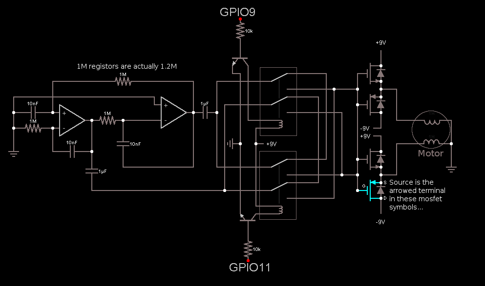
Basically you only need a stepper motor (actually an array, but bear with me) to drive and a clever way to set it on and off and make it rotate prograde or retrograde at the right time. So first, there an OpAmp Phase Shift oscillator stage that generates the sine and cosine waveforms that make the motor rotate. These signals are redirected and switched by a low-voltage relay contraption which is driven by a computer with MOSFETs into two push-pull MOSFET amplifiers (each for each waveform). The motor connects to the amplifier's output.
The computer is a Raspberry Pi running a python script which I won't show as of yet under the embarrassment of its... say, incompleteness...
The GPIO of the Raspi puts on high one of its pins to make the motor rotate in one direction and turn other pin high to make the motor rotate the other direction: both pins low means the motor is stopped by means of no relay allows the oscillator waveform to get to the amplifier.
Does this work? Well...
Given I'm not as much expert in electronics as I wanted, the fact that I only have one stepper motor yet and that this circuit seems to be unreliable 40% of the time... What's you measure of success?
I believe I should be using bipolar transistors instead of MOSFETs, but I couldn't get them work for some weird reason. Also the fact that I'm not using a microcontroller and instead rely on direct computer control can be argued against by saying that computers don't work in real time or are fast enough, but since I've seen some guys remote controlling a quadcopter with a Raspi, I believe anything. I plan to use parallel processing to control simultaneously the various motors and bypass computer control for bed and nozzle heating, by instead using looped feedback circuits (maybe with electronic neurons or differential amplifiers and such). This is unless someone points out a better idea!
).I've got into building a RepRap (a Prusa 2 FIY) myself, but found the electronics to be quite expansive. So, being a fan of BEAM philosophy, I took on the adventure of trying to do away with microcontrollers (and maybe, eventually computers) to control the RepRap.
The following circuit is what I came up with.
[I'll add pictures at a later edit and schematic if you are interested]
Basically you only need a stepper motor (actually an array, but bear with me) to drive and a clever way to set it on and off and make it rotate prograde or retrograde at the right time. So first, there an OpAmp Phase Shift oscillator stage that generates the sine and cosine waveforms that make the motor rotate. These signals are redirected and switched by a low-voltage relay contraption which is driven by a computer with MOSFETs into two push-pull MOSFET amplifiers (each for each waveform). The motor connects to the amplifier's output.
The computer is a Raspberry Pi running a python script which I won't show as of yet under the embarrassment of its... say, incompleteness...
The GPIO of the Raspi puts on high one of its pins to make the motor rotate in one direction and turn other pin high to make the motor rotate the other direction: both pins low means the motor is stopped by means of no relay allows the oscillator waveform to get to the amplifier.
Does this work? Well...
Given I'm not as much expert in electronics as I wanted, the fact that I only have one stepper motor yet and that this circuit seems to be unreliable 40% of the time... What's you measure of success?
I believe I should be using bipolar transistors instead of MOSFETs, but I couldn't get them work for some weird reason. Also the fact that I'm not using a microcontroller and instead rely on direct computer control can be argued against by saying that computers don't work in real time or are fast enough, but since I've seen some guys remote controlling a quadcopter with a Raspi, I believe anything. I plan to use parallel processing to control simultaneously the various motors and bypass computer control for bed and nozzle heating, by instead using looped feedback circuits (maybe with electronic neurons or differential amplifiers and such). This is unless someone points out a better idea!
|
Re: My attempt at the cheapest control board possible. May 30, 2013 06:13AM |
Registered: 13 years ago Posts: 7,616 |
I don't think a high level language like Python running on a general purpose OS can meet the step time requirements required to move a stepper at a reasonably quick rate. You'd need at least a real-time OS; most (all?) RepRap controllers run no OS at all, but the code "directly" on the hardware.
| Generation 7 Electronics | Teacup Firmware | RepRap DIY |
|
Re: My attempt at the cheapest control board possible. May 30, 2013 08:58AM |
Registered: 12 years ago Posts: 212 |
Hi dig_gil,
you might take a look at the Beaglebone, it's embedded ARM has two 200MHz auxiliary MCUs they can do the timing critical stepper related stuff, the rest can be done in a highlevel Language. This is like it is done e.g. with the replicape.
Grüße / Regards
STB
______________________________________________________________
Basics about MOSFETs
|
Re: My attempt at the cheapest control board possible. May 30, 2013 12:40PM |
Registered: 14 years ago Posts: 177 |
Before re-inventing the wheel, look around the local interest groups, they might have 2nd hand parts, or some advice on saving money in purchase.
I would suggest you to go with a proper driver - maybe Toshiba TB6560 which is significantly cheaper here but works. The hotend will give you enough headache, and you don't want to have even more bugs/quality issue/smoke due to the control system.
I would suggest you to go with a proper driver - maybe Toshiba TB6560 which is significantly cheaper here but works. The hotend will give you enough headache, and you don't want to have even more bugs/quality issue/smoke due to the control system.
|
Re: My attempt at the cheapest control board possible. June 15, 2013 10:45AM |
Registered: 10 years ago Posts: 3 |
Sorry about taking so much time to return. I couldn't find a camera which would work properly, but what matters the most is the schematic, I guess. Check the attached file for that.
I got it to work, but there's still some instability source to figure out. I'll try asking for a burrowed oscilloscope at school. I guess that it's either the oscillator stage that goes out of synchronism between its phases at moments, or the amplifier stage that's unbalanced (somehow/somewhat), or the motor is temperamental when using sinewaves which are switched by relay (transients?).
If you spot something that might be causing me trouble, I'd be glad to know. I'll be posting more in here to let you know development until I get these kinks ironed out. In the future I plan to use ganged up potentiometers instead of the 1.2MOhm ones so to control motor speed.
Edited 1 time(s). Last edit at 06/15/2013 12:10PM by dig_gil.
|
Re: My attempt at the cheapest control board possible. June 17, 2013 06:51AM |
Registered: 14 years ago Posts: 177 |
|
Re: My attempt at the cheapest control board possible. June 17, 2013 10:54PM |
Registered: 13 years ago Posts: 1,352 |
|
Re: My attempt at the cheapest control board possible. June 19, 2013 08:39AM |
Registered: 10 years ago Posts: 3 |
NoobMan Wrote:
-------------------------------------------------------
> I think those may be sort of an enable/disable
> therefore rarely used. Why didnt you asked why
> there are two of them, coz there is only one line
> they are swtiching and just makes circular loops
> currents.
Could you better explain please? I think you said something useful, but I can't understand what you mean. While trying to get what you've said, I've noticed a mistake in the schematic: the two mosfet pairs shouldn't be connected by their gates. If that's what you meant, this mistake is not featured in the circuit I've built.
I thought that maybe I should add filtering capacitors between the motor and ground (or amplifier).
|
Re: My attempt at the cheapest control board possible. June 19, 2013 01:20PM |
Registered: 12 years ago Posts: 195 |
sam0737 is right. You should be using transistors as an H-bridge as your relays will die fairly quickly in this application. Consider the TB6560 he mentioned, as it's really cheap (probably cheaper than 2 DPDT relays). Controllers like that will give you microstepping, thermal protection, and a easy logic drive, which you won't get with relays or transistors.
|
Re: My attempt at the cheapest control board possible. June 19, 2013 05:41PM |
Registered: 13 years ago Posts: 1,352 |
dig_gil Wrote:
-------------------------------------------------------
> Could you better explain please? I think you said
> something useful, but I can't understand what you
> mean. While trying to get what you've said, I've
> noticed a mistake in the schematic: the two mosfet
> pairs shouldn't be connected by their gates. If
> that's what you meant, this mistake is not
> featured in the circuit I've built.
Yes, the picture shows only one line coz all gates are tied together, that was exactly what i meant. If you changed that its ok.
Sorry, only registered users may post in this forum.