Stepper Driver Circuit effecting thermocouple temperature??
Posted by cpwebste
|
Stepper Driver Circuit effecting thermocouple temperature?? March 29, 2009 11:41AM |
Registered: 15 years ago Posts: 52 |
I am working on finishing up the electronics for my repstrap and noticed something odd while testing it. When I first turn on the power supply and start the host software, the temperature is correct (I'm checking it with my multimeter). However, once I start moving motors around (specifically the extruder motor) the temperature changes by a good 15˚C. This is a problem for obvious reasons. I have a feeling it might have something to do with the large current draw on the power rails when the motors are running (2 Amps each), not sure though? I had tested the thermocouple circuit before with the extruder motor and it worked fine so I'm at a loss for what is changing when I connect everything else together. Any ideas?
|
Re: Stepper Driver Circuit effecting thermocouple temperature?? March 29, 2009 12:17PM |
Registered: 15 years ago Posts: 52 |
I also noticed that when I plug in all 4 of my motors, the Z axis stepper no longer has enough torque to move than platform. My power supply can support up to 18 Amps on the 12V rail so I'm thinking that wouldn't be a problem with that, but what else could be the culprit? I have the whole circuit on a breadboard and have one molex connector powering the entire thing (+5V). Maybe I need to use the 4 pin CPU connector for getting more current??
Edited 1 time(s). Last edit at 03/29/2009 12:51PM by cpwebste.
[cpwebste.blogspot.com]
Edited 1 time(s). Last edit at 03/29/2009 12:51PM by cpwebste.
[cpwebste.blogspot.com]
|
Re: Stepper Driver Circuit effecting thermocouple temperature?? March 29, 2009 01:04PM |
Registered: 15 years ago Posts: 332 |
You could try adding a hefty capacitor near the stepper drivers. I was getting weird loss of power issues until I added about 30000uF in capacitors to each board. There's probably a more elegant way though. The change in temperature reading I would guess is because the supply voltage to the microcontroller is fluctuating, though I may be wrong. A capacitor either on the microcontroller power supply or on the temperature input pin might work. Are you sure all 18 amps come from the same 12v rail? You might need to harness all the yellow leads to get the full current.
|
Re: Stepper Driver Circuit effecting thermocouple temperature?? March 29, 2009 02:12PM |
Registered: 15 years ago Posts: 186 |
Note that some cheap'n'cheerful computer power supplies have been found to handle far less than the currents stated on the box. Typical computer use doesn't often hit the max, so they work fine in PCs.
I've had problems building high-powered PCs where a '500w' PSU couldn't supply enough current on the 12v line for the machine to boot when everything was plugged in. 'named' brands often supply much nearer the specs, and usually smoother current.
I've had problems building high-powered PCs where a '500w' PSU couldn't supply enough current on the 12v line for the machine to boot when everything was plugged in. 'named' brands often supply much nearer the specs, and usually smoother current.
|
Re: Stepper Driver Circuit effecting thermocouple temperature?? March 29, 2009 03:08PM |
Registered: 15 years ago Posts: 52 |
Good to know. I followed James' advice and basically connected every 5V pin that the power supply has together and ran it to the breadboard. That offered enough current for everything to turn smoothly. As for the thermocouple issue, I still haven't figured it out. Basically it works right when I turn it on. If I just move the Z axis after powering everything up it works fine. The moment I move the X and Y axes, the temperature jumps 15˚C up to around 35˚C and then holds steady there (room temp was about 20˚C). I tried powering the TC circuit using a AA battery to isolate any effects of the motors on the power supply. This made the temp stay basically constant while moving the X and Y axes, but the temp kept dropping by a degree or two per minute. I'm thinking the AA's were just dying (they're pretty close to dead now). So any ideas maybe about how I could isolate the TC circuit better?
[cpwebste.blogspot.com]
[cpwebste.blogspot.com]
|
Re: Stepper Driver Circuit effecting thermocouple temperature?? March 29, 2009 08:05PM |
Registered: 15 years ago Posts: 478 |
You could use A 7805 Voltage regulator to run the Thermocoule sensor on.
Here is a Typical Circuit you could use. If you run more than the temprature sensor on this supply you will need a small heat sink. The voltages of the capacitors need to be high enough for the voltage so they could be any > 12v typicaly 16v

Picture size adjusted to bigger and spelling corection
Edited 2 time(s). Last edit at 03/29/2009 08:43PM by BodgeIt.
Bodge It [reprap.org]
=======================================
My rep strap: [repstrapbertha.blogspot.com]
Buy the bits from B&Q pipestrap [diyrepstrap.blogspot.com]
How to Build a Darwin without any Rep Rap Parts [repstrapdarwin.blogspot.com]
Web Site [www.takeaway3dtech.com]
Here is a Typical Circuit you could use. If you run more than the temprature sensor on this supply you will need a small heat sink. The voltages of the capacitors need to be high enough for the voltage so they could be any > 12v typicaly 16v
Picture size adjusted to bigger and spelling corection
Edited 2 time(s). Last edit at 03/29/2009 08:43PM by BodgeIt.
Bodge It [reprap.org]
=======================================
My rep strap: [repstrapbertha.blogspot.com]
Buy the bits from B&Q pipestrap [diyrepstrap.blogspot.com]
How to Build a Darwin without any Rep Rap Parts [repstrapdarwin.blogspot.com]
Web Site [www.takeaway3dtech.com]
|
Re: Stepper Driver Circuit effecting thermocouple temperature?? March 30, 2009 07:27AM |
Registered: 15 years ago Posts: 52 |
I just happen to have a couple L7805CVs sitting around so I will try to find space for this on the breadboards tonight. One additional question, what the arduino thinks is +5V needs to be the same as what the TC chip sees as 5V right? So should I connect the arduino 5V pin to the output from this regulator as well? I'm not sure if that 5V pin on the arduino is a output, reference input, or something else entirely.
[cpwebste.blogspot.com]
[cpwebste.blogspot.com]
|
Re: Stepper Driver Circuit effecting thermocouple temperature?? March 30, 2009 08:41AM |
Admin Registered: 17 years ago Posts: 7,879 |
I think that the ADC in the Arduino use the 5V rail as its reference voltage. When using a thermistor, which forms a protential divider also driven from the 5V rail, the actual rail voltage does not matter. The thermistor converts the temperature to a fraction of VCC and then the ADC converts the fraction of VCC to a number.
On the other hand the thermocouple chip produces an absolute voltage, which is then measured as a fraction of VCC, so the result is never going to more accurate than your VCC, which is usually +/-5% using a standard regulator.
So you need a good regulated supply to the Arduino 5V rail. I don't think it is absolutely necessary to feed the TC board from the same supply, but it would not be a bad idea to do that.
You problems with the 12V rail may be due to not having enough load on the 5V rail of the PSU. You generally need to load the 5V rail with at least 0.5A to get the 12V rail to regulate properly. Possibly you would need to load the 3.3V rail as well if the PSU has one.
Edited 1 time(s). Last edit at 03/30/2009 12:34PM by nophead.
[www.hydraraptor.blogspot.com]
|
Re: Stepper Driver Circuit effecting thermocouple temperature?? March 30, 2009 09:55AM |
Registered: 15 years ago Posts: 52 |
I am currently supplying all the motors with the 5V rail. I may move to 12V eventually, but at the moment I'm keeping the current through the motors down. The 5V rails can supply 25 Amps from the power supply so it is more than capable. I will try out regulating the arduino and TC chip tonight. I did look around at other 5V regulator circuits with the L7805 and noticed some variation on the capacitor values. For example one used a 100uF and 10uF electrolytics along with a 0.1uF ceramic. What is the design equations for these values? I am using a L7805CV if it helps, and I looked through the datasheet and couldn't find anything about what specific values to use and if they change at all.
Side note: I finished the final touches on the mechanical parts of the repstrap so all that's left is to get the electronics working reliably and I can get some test objects printed! See the blog below for my progress
[cpwebste.blogspot.com]
Side note: I finished the final touches on the mechanical parts of the repstrap so all that's left is to get the electronics working reliably and I can get some test objects printed! See the blog below for my progress
[cpwebste.blogspot.com]
|
Re: Stepper Driver Circuit effecting thermocouple temperature?? March 30, 2009 11:13AM |
Registered: 15 years ago Posts: 332 |
The value of the capacitors is not too important - they're just there to smooth the output of the regulator. I believe the electrolytic capacitors from about 10uf upwards help correct low frequency wobbles in output voltage and the ceramic ones filter high frequency noise. You could try adding a resistive load to the 5v line, the motors will briefly draw no current as they spin, causing voltage fluctuations. I wired a 500ma 12v halogen bulb to the 5v rail, which helped things.
|
Re: Stepper Driver Circuit effecting thermocouple temperature?? March 30, 2009 02:56PM |
Registered: 15 years ago Posts: 478 |
The values of the capacitors on the 5v side do not matter to much the type of capacitor can make a difference the 1uf-10uf would usually be a tantalum capacitor to remove regulator noise with the 0.01 ceramic.
The capacitors on the 12V side as a general rule the bigger the better to provide a stiffer source making the cct less susceptible to voltage variations.
In the case of running from a switch mode PS and with a PD of 7V you don’t really need to be too worried. However the heat that will be dissipated by the regulator will be 7V * (the current)=W you are using. Hence you will need to fit a heat sink if you run more than just the thermocouple sensor on the 7805 regulator.
The 78L05 is 100mA Max current 7805 has 1A max current.
By wiring the power supply lines from a central node you can decrease the effect of noise and voltage drop caused by the power circuits
On my machines I keep the stepper controllers on a separate set of set of drive cables to the control electronics A diagram is better to show this:-
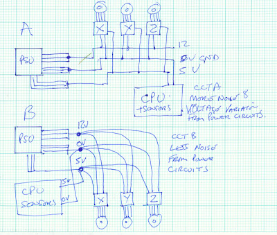 CCTA. The power to the CPU/sensor electronics is directly is affected by the Voltage drop due to stepper current and noise generated from all the stepper controllers and their motors.
CCTB. The power to the CPU/sensor electronics is not directly is affected by the Voltage drop due to stepper current and noise generated from all the stepper controllers and their motors.
CCTA. The power to the CPU/sensor electronics is directly is affected by the Voltage drop due to stepper current and noise generated from all the stepper controllers and their motors.
CCTB. The power to the CPU/sensor electronics is not directly is affected by the Voltage drop due to stepper current and noise generated from all the stepper controllers and their motors.
Bodge It [reprap.org] ======================================= My rep strap: [repstrapbertha.blogspot.com] Buy the bits from B&Q pipestrap [diyrepstrap.blogspot.com] How to Build a Darwin without any Rep Rap Parts [repstrapdarwin.blogspot.com] Web Site [www.takeaway3dtech.com] |
|
Re: Stepper Driver Circuit effecting thermocouple temperature?? March 30, 2009 03:54PM |
Registered: 15 years ago Posts: 52 |
My question to your technique would be are the GND/5V/12V lines not connected once you get inside of the power supply. I envision one massive 5V node that supplies 5V to all the 5V outputs from the power supply. In this case, I don't see how using different taps to that line would make any difference. If that is not the case and the different Molex cables have different supply circuits inside of the power supply than doing this would definitely help. Anyone know more about power supplies who can elaborate on this or am I missing something from the diagram above?
Second, in the diagram above, why do you have 5V and 12V connected to the motors? Wouldn't just one of those be sufficient?
Third, as I am trying to work out this 5V regulator to the TC/Arduino I ran into a question. The 5V pin on the Arduino: what is the actual function of this? I know if you power this pin with 5V the Arduino will be powered up, but what if you connect the Arduino the a computer via a USB connection? Will that take precedence over the 5V input pin? I am just trying to figure out how to power both the Arduino and Thermocouple IC off the same supply.
Help on any of these issues would be appreciated.
[cpwebste.blogspot.com]
|
Re: Stepper Driver Circuit effecting thermocouple temperature?? March 30, 2009 07:34PM |
Registered: 15 years ago Posts: 478 |
Yes inside the PC SW mode supply there are large node pads for each supply voltage. On most of these power supplies you only have 2 maybe 3 Molex drive connections.
Here is a diagram indicating the connections to the mother bd.
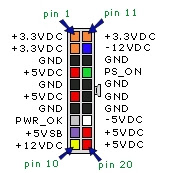
This mother board connection has:-
4 Red wires 5v
7 Black wires 0v
1 Yellow 12V
These are the addition wires used to make the 12V 5V and Ground connections to
The RRRF stepper controllers use all three supply wires.
Which Arduino board do you have?
The Tinker.it Arduino decimal I have:-
Already has a 5v regulator on board that is selected via a link.
The link selects power from USB cable or power from DC power pack.
On my machine I have removed the link so its not connected to either.
The power for the Arduino is connected via the break out board to the PC PSU 5V supply and Ground.
My Sanguino board also has a Voltage regulator on board.
I have removed the power selection link on this as well.
As the power is also connected via the header pins.
The Sanguino.
I connected both this way as I did not want to take power via USB or have a collection of little black power boxes
My suggestion would be to provide very clean power to the Thermocouple bd from the 12v supply / in place of using batteries.
Bodge It [reprap.org]
=======================================
My rep strap: [repstrapbertha.blogspot.com]
Buy the bits from B&Q pipestrap [diyrepstrap.blogspot.com]
How to Build a Darwin without any Rep Rap Parts [repstrapdarwin.blogspot.com]
Web Site [www.takeaway3dtech.com]
Here is a diagram indicating the connections to the mother bd.
This mother board connection has:-
4 Red wires 5v
7 Black wires 0v
1 Yellow 12V
These are the addition wires used to make the 12V 5V and Ground connections to
The RRRF stepper controllers use all three supply wires.
Which Arduino board do you have?
The Tinker.it Arduino decimal I have:-
Already has a 5v regulator on board that is selected via a link.
The link selects power from USB cable or power from DC power pack.
On my machine I have removed the link so its not connected to either.
The power for the Arduino is connected via the break out board to the PC PSU 5V supply and Ground.
My Sanguino board also has a Voltage regulator on board.
I have removed the power selection link on this as well.
As the power is also connected via the header pins.
The Sanguino.
I connected both this way as I did not want to take power via USB or have a collection of little black power boxes
My suggestion would be to provide very clean power to the Thermocouple bd from the 12v supply / in place of using batteries.
Bodge It [reprap.org]
=======================================
My rep strap: [repstrapbertha.blogspot.com]
Buy the bits from B&Q pipestrap [diyrepstrap.blogspot.com]
How to Build a Darwin without any Rep Rap Parts [repstrapdarwin.blogspot.com]
Web Site [www.takeaway3dtech.com]
|
Re: Stepper Driver Circuit effecting thermocouple temperature?? March 30, 2009 08:44PM |
Registered: 15 years ago Posts: 52 |
Thanks for the reply BodgeIt. I have the Arduino Decimilia for reference. I think I may have stumbled upon something that might be causing this. As per your suggestions I have removed the jumper on the Arduino for selecting between USB or external (9V with onboard regulator I think). It appears that this makes the 5V pin on the Arduino the sole source of power. After doing this I powered both the Thermocouple chip and the Arduino off the output from the L7805 5V regulator circuit which was providing a very stable 5V output. The 7805 was taking a 12V input from the power supply. The only other items using this are the heater FET. All the motors and drivers are on the 5V line from the power supply. This setup appeared to be giving a stable temperature, but when firing up the motors the temp jumped 10˚C right away, same as before. After touching the barrel I realized that it did actually seem a little hot. My handheld multimeter probably doesn't have the most accurate temp reading but it is usually within 5˚C of what the host software is saying the temp is.
Anyways, what I think might be happening is that the temperature is in fact jumping. When the motors suddenly draw so much current I think it is making the heater FET pass a small amount of current through the heater coil. Either way it's not a lot so I think for now I am going to be content with my much more reliable regulated supply for the temperature sensor and Arduino. Hopefully, this effect will be minimized once the heater is turned on and current is already flowing through it. If anyone has any other ideas about this feel free to shout out!
[cpwebste.blogspot.com]
|
Re: Stepper Driver Circuit effecting thermocouple temperature?? April 30, 2014 09:52PM |
Registered: 10 years ago Posts: 62 |
I'm getting a similar issue with the AD595 board using a thermocouple. Whenever I hit the extruder, temp jumps up about 50C (from 250 to 300). But when I extrude by hand by physically turning the gear, it works fine.
Right now I've got the AD595 kit board from Makerbot hooked up to AUX-1 pins of RAMPS 1.4 (5v, ground, and Analog 3 on the Arduino Mega). Is there a way to do this without having to add capacitors?
Right now I've got the AD595 kit board from Makerbot hooked up to AUX-1 pins of RAMPS 1.4 (5v, ground, and Analog 3 on the Arduino Mega). Is there a way to do this without having to add capacitors?
|
Re: Stepper Driver Circuit effecting thermocouple temperature?? May 12, 2014 05:56PM |
Registered: 12 years ago Posts: 283 |
I believe the stoppers are running in constant current mode so running them at 5 volts probably won't make a difference. Id move them onto the 12v rail and use the trim puts on the polulo boards to set the current. This should also help you temperature problem.Quote
I am currently supplying all the motors with the 5V rail. I may move to 12V eventually, but at the moment I'm keeping the current through the motors down.
Using ABSPrusa Mendel Zaphod with Pronterface and slic3r 1.3.0. Printing well with 3mm PLA and ABS through 2 x J Head Mk IV b and Wade Geared Exruders. Controlled using RAMPS1.4 board running Marlin_v1.1.9
|
Re: Stepper Driver Circuit effecting thermocouple temperature?? May 15, 2014 10:30AM |
Registered: 11 years ago Posts: 117 |
I am also running AD595 thermocouple board and ATX PSU. Same problems with temperature, it rises about 20 degrees celsius when I enable motors. Heating the bed does not affect temperature, so I suspect there is some EMI going on with the signal wire, or the 5V reference line drops when the stepper drivers start consuming power. A better solution to AD595 would be something with digital output, such as MAX series.
Edited 1 time(s). Last edit at 05/15/2014 10:54AM by jkoljo.
Edited 1 time(s). Last edit at 05/15/2014 10:54AM by jkoljo.
Sorry, only registered users may post in this forum.