Dual extrusion TB6560 controller
Posted by vajpeters
|
Dual extrusion TB6560 controller November 10, 2013 07:06AM |
Registered: 11 years ago Posts: 33 |
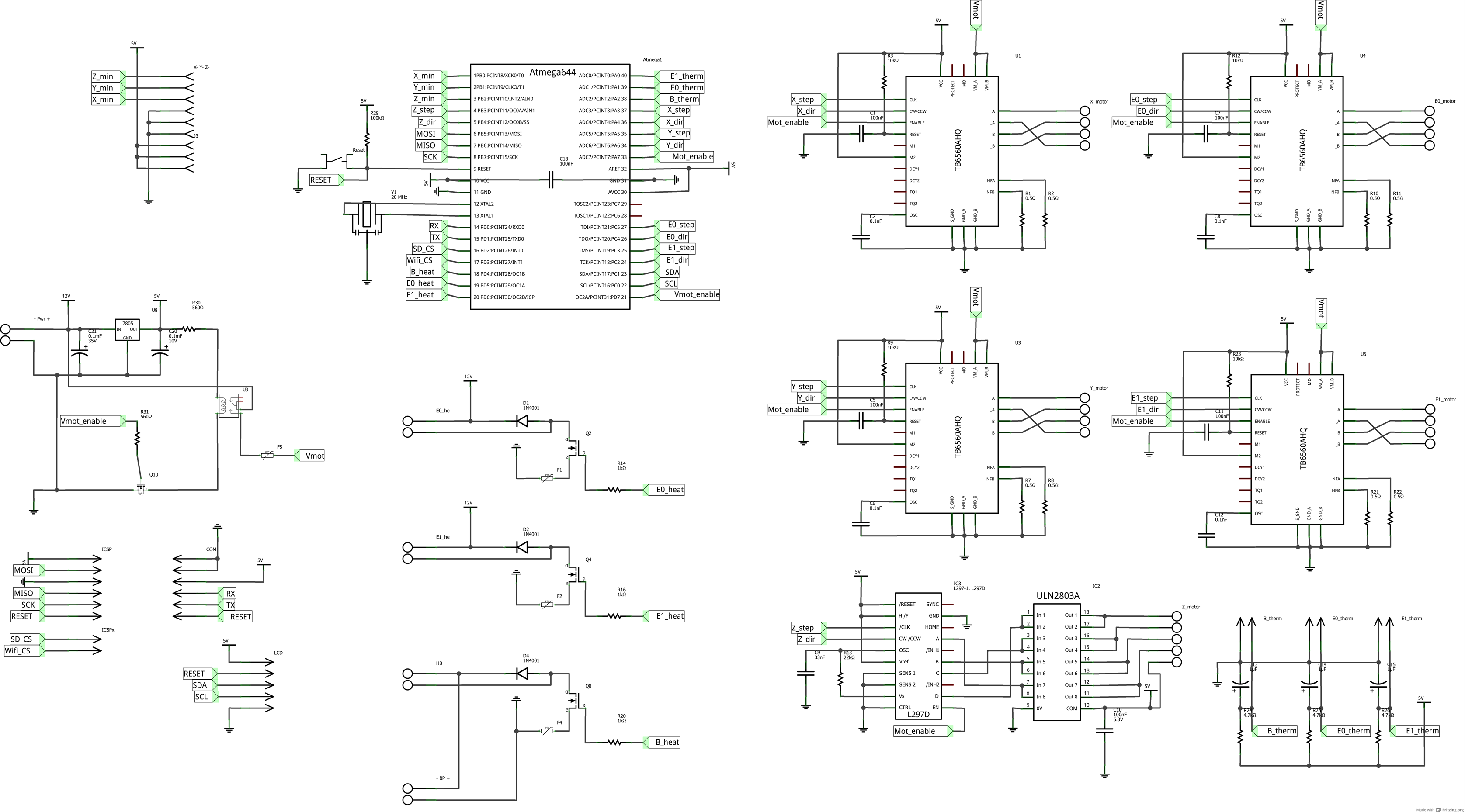
After reading a lot of stuff in the Sanguish forum topic, I came up with the idea to step it up to the next level: dual extrusion. At the same time I wanted the controller to be cheap, easy and packed with as much features as possible. The design requirements set are the following:
- Heated Print Bed
- Dual hot-end
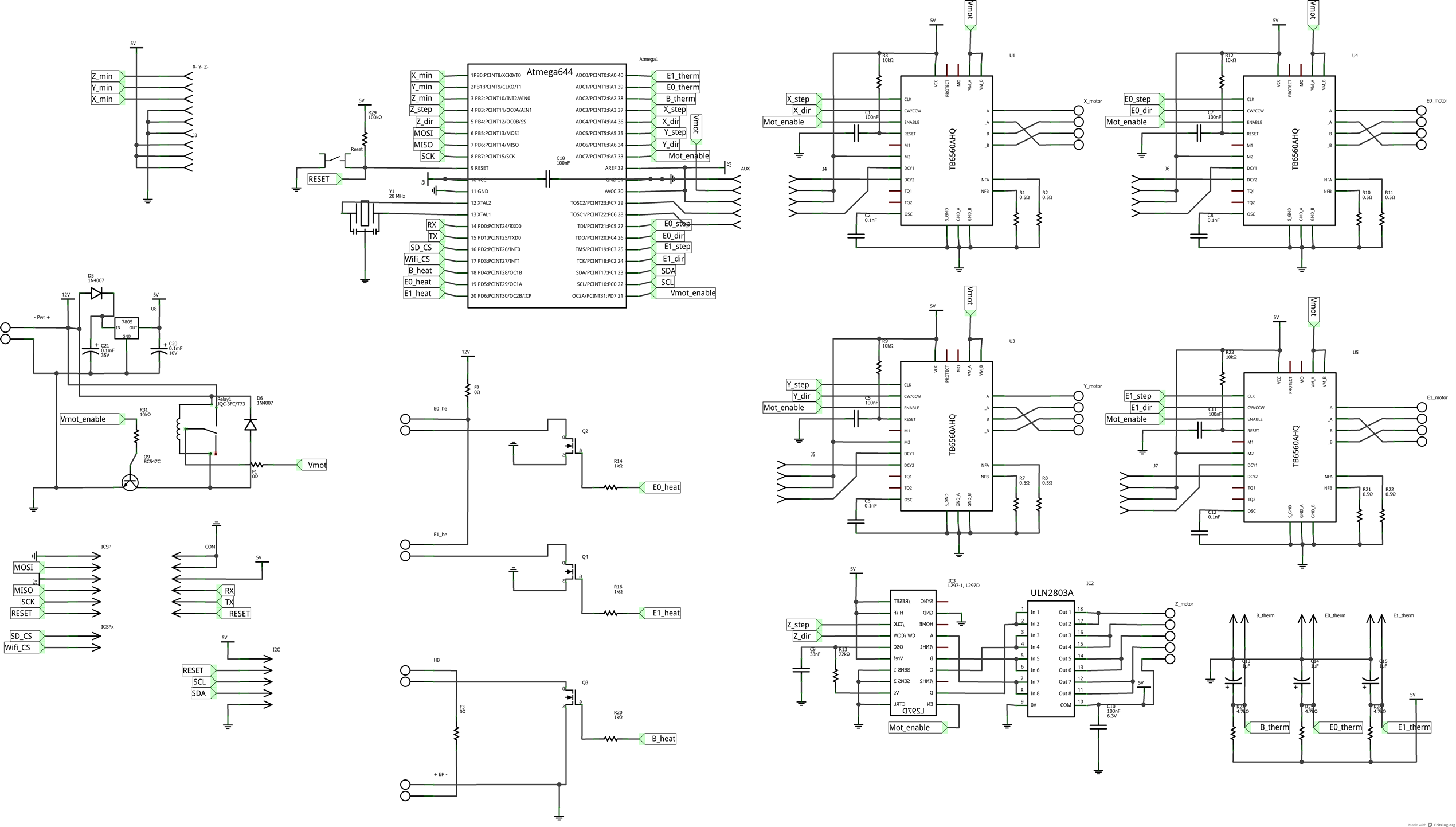
- 4 TB6560 for X, Y, E0 and E1
- L297 + ULN2803 for Z axis (to make the use of cheap 35BYJ412B motors)
- I2C port (for LCD displays, I/O expansion, etc.)
- Design in Fritzing
- No larger than 100mm x 100mm
- Loosely based on Sanguish, Gen7 and Sanguinololu
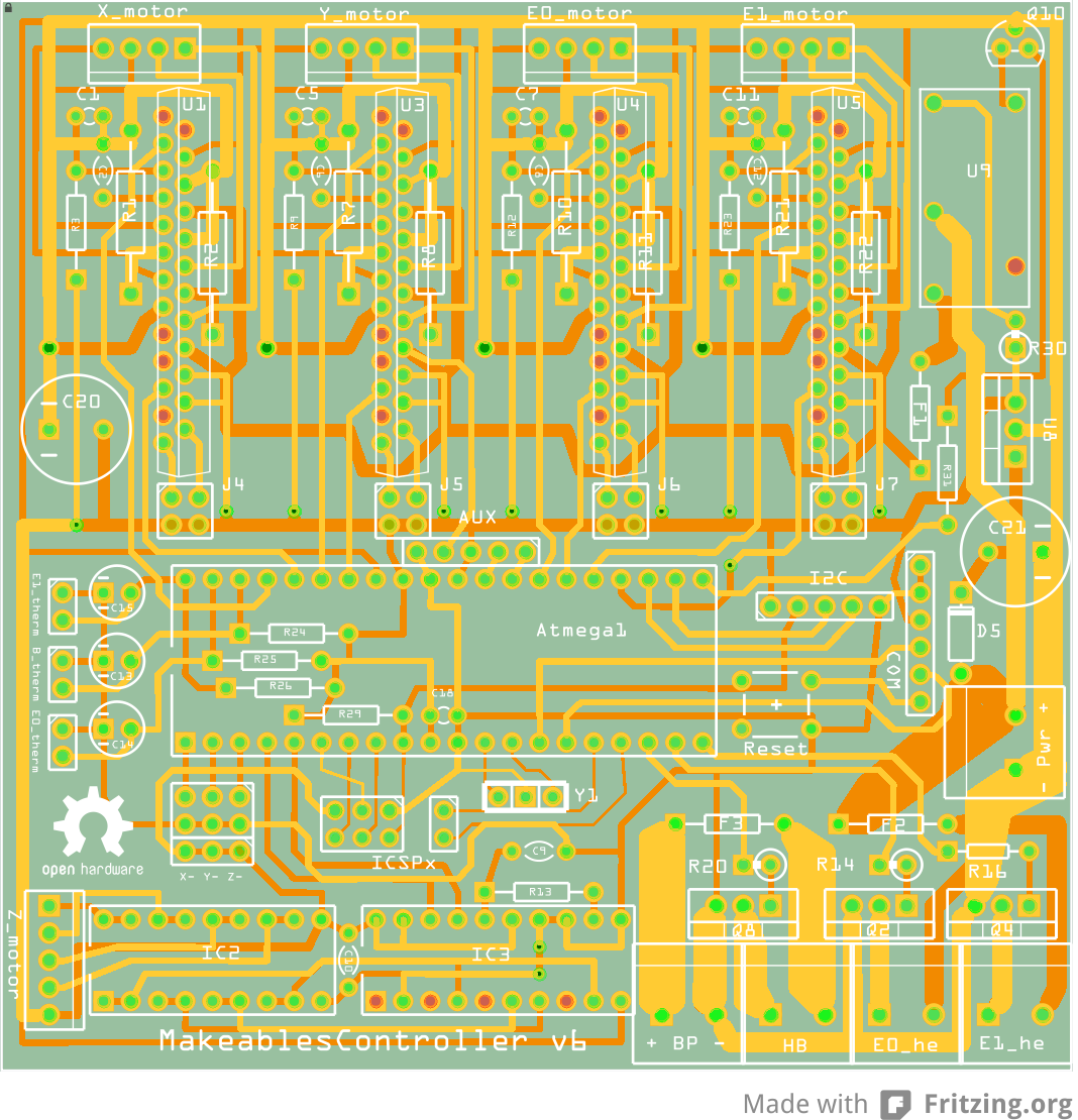
So after some hours of puzzeling, I came up with the design as attached. The ICSP connector has two pins extra to the right (that's why I called it ICSPx) where chip select pins can be connected to. The COM port is standardised to use USB2SerialTTL boards (cheaply available on eBay), but can also use bluetooth or any other serial communication line.
Would it be possible for some of you to review my design and give me some help in debugging the concept?
- Heated Print Bed
- Dual hot-end
- 4 TB6560 for X, Y, E0 and E1
- L297 + ULN2803 for Z axis (to make the use of cheap 35BYJ412B motors)
- I2C port (for LCD displays, I/O expansion, etc.)
- Design in Fritzing
- No larger than 100mm x 100mm
- Loosely based on Sanguish, Gen7 and Sanguinololu
So after some hours of puzzeling, I came up with the design as attached. The ICSP connector has two pins extra to the right (that's why I called it ICSPx) where chip select pins can be connected to. The COM port is standardised to use USB2SerialTTL boards (cheaply available on eBay), but can also use bluetooth or any other serial communication line.
Would it be possible for some of you to review my design and give me some help in debugging the concept?
|
Re: Dual extrusion TB6560 controller November 12, 2013 12:16PM |
Registered: 13 years ago Posts: 632 |
Looks nice. Here are a few things I noticed that you might not have.
One of the resistors inside the ATMega socket is pretty close to the edge. It might hit the socket frame.
You don't have the torque jumper pins wired up. This means no current adjustment at all. Might be a bit limiting, as this is one of the deficiencies of the drivers already.
Similarly the decay mode jumpers. I haven't done much research yet, but looking at Nophead's work that might be useful to prevent skipped microsteps.
One current sense resistor per coil. For 2 amps per coil you'll need a 0.25 ohm 1 watt resistor. These resistors might be bigger than you have provided space for lengthwise.
If you move the extra pins next to ICSP header out one space they will match the SDSL pinout. But maybe you were going for compatibility with something else.
What fuses are you using? They look nice and small. I'd like to get some.
Similarly what relay?
Bryan
|
Re: Dual extrusion TB6560 controller November 21, 2013 05:12AM |
Registered: 11 years ago Posts: 33 |
First of all, thanks to Bryan for reviewing my work. I appreciate it a lot!
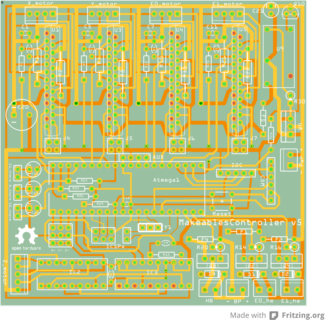
The points you bring to my attention I have solved more or less in the attached version. So here are the changes:
- The resistors inside the Atmega frame I have replaced a little more inside the frame, so that no collision will occur when assembling.
- The torque pins are still not wired up, my plan is to use the resistors for torque setting. I know this seems limiting, but I don't see a way to breakout the pins to a jumper.
- The decay pins I have brought to a jumper header. Setting these might come in handy, you can always choose to not use them. I haven't found any documentation on Nopheads work, so if somebody can post a link, I would really like to read some about it.
- I have provided more space for the resistors, I actually took one and measured it's footprint to be absolutely sure. The resistor on the right of the driver needs to be bended a little to the outside before mounting the driver chip. To me this is no real problem, but if somebody thinks it is, give me some feedback and ideas..
- The ICSP pinout is made compatible to the SDSL pinout. A SDSL card should work with this board without any strange modifications other than (configuration)code.
- The fuses I'm using are from RS. I use the 11A (647-8651) and the 5A (647-8617) version. The foot print was previously a little to small,so I have enlarged this to provide more space.
- The relay I will use, will be a G5Q type, these are a little more expensive (around 2eur/pc) but also a little smaller. On the previous board I used the wrong footprint, but this is corrected in the attached version.
On top of that, I have cleaned up the silkscreen and added an AUX port to break-out 2 unused pins that might be come in handy when using a fan or so. But since I had no real plan, I leave this upto the user. The next steps I'd like to take is prototyping and opening up the design for the public by making the design files (in Fritzing) ready for download on my website. Together with the Fritzing files, I will also publish the BOM and the 'makers-guide'. If there is interest in ready made boards and/or kits, I will make a small production run to provide to community with these controllers.
Again: all feedback is welcome. I plan to prototype a few of these boards next week, so if something seems to be wrong, please let me know!
|
Re: Dual extrusion TB6560 controller November 23, 2013 01:45PM |
Registered: 13 years ago Posts: 632 |
My last suggestion would be to think about current and trace width. With 5 steppers, a HBP, and two hot ends, you could be running 30 amps or more total. Make sure your power supply connectors can handle it. Also the traces to HBP look a bit thin for 10A. At first I didn't see the separate HBP power supply connector, so you might be good. As long as you have space you might as well thicken up the high current traces.
Also I would probably start a new topic in the main electronics section. This section doesn't get much traffic at all.
Edited 3 time(s). Last edit at 11/23/2013 02:03PM by bryanandaimee.
Also I would probably start a new topic in the main electronics section. This section doesn't get much traffic at all.
Edited 3 time(s). Last edit at 11/23/2013 02:03PM by bryanandaimee.
|
Re: Dual extrusion TB6560 controller November 25, 2013 01:02PM |
Registered: 10 years ago Posts: 1,433 |
You will need a much wider trace for power ground and for power in. The traces you have are much smaller than they need to be.
I'd put a diode in front of the 7805. It can help a bit in odd shutdown situations.
You might think about automotive fuses in place of the PTC parts from Bourns. The cost / board space is no worse and they work a lot better. If you ever decide to go above 12V they will still work ok. The Bourns parts are only rated for 16V. They also have a maximum current rating that you may or may not comply with on this or that power supply. Yes they are used on a lot of these boards, they also fail on a them as well.
|
Re: Dual extrusion TB6560 controller November 25, 2013 05:18PM |
Registered: 11 years ago Posts: 33 |
Hmm, nice suggestions.
- One thing I should have told you about the board design: it's dual sided, so the power traces for the heated bed are also placed on both sides. According to my calculations, a 48mil trace should be able to carry 5-6Amps without heating up too much. So my dual sided construction should be able to transfer at least around 10Amps without getting into trouble. But this is something which needs to be tested.
- The diode on the 7805 is a nice suggestion, I will add it in the next version.
- The automotive fuses are also a nice thing to test. I have a couple of these on my desk since I like to work on my two oldtimer cars.
I have ordered 10 boards for testing purposes. I will check the basic functions, but in the meantime I keep working perfecting the v6 board. So any suggestions and/or comments are welcome!
|
Re: Dual extrusion TB6560 controller November 25, 2013 06:54PM |
Registered: 10 years ago Posts: 1,433 |
You want the traces to be able to handle a near short circuit condition that's under the trip point on your fuses. In the case of the 11A PTC fuses that's roughly 22A. A lot of the calculators out there assume that you have an ideal board with the amount of copper you ordered on all traces. In an ideal world you would get that. In the real world a trace that's at 2/3 the spec is a much more likely case. That's even more true if you are buying boards from a low cost / quick turn outfit. They forecast one number for an inner layer and another for an outer layer. That assumes you have air able to get to the outer layer. If you have a connector on one side of the board, and the other side against a mounting plate .... not so much...
|
Re: Dual extrusion TB6560 controller November 26, 2013 02:27AM |
Registered: 11 years ago Posts: 33 |
|
Re: Dual extrusion TB6560 controller November 26, 2013 01:45PM |
Registered: 10 years ago Posts: 1,433 |
If you are running 2 ounce copper, I'd take them up to at least 0.2" on both sides for power. Most times it's easier to do this stuff with a copper pour / plane than with a trace. For ground, go for how ever much beyond 0.2 you can get in there. Having ground come loose / bounce is not a good thing.
I'm still not quite seeing how you are getting all the ground and power duplicated on both sides. The pcb layout sure looks like some of the ground is under some of the power.
Edited 2 time(s). Last edit at 11/26/2013 01:51PM by uncle_bob.
I'm still not quite seeing how you are getting all the ground and power duplicated on both sides. The pcb layout sure looks like some of the ground is under some of the power.
Edited 2 time(s). Last edit at 11/26/2013 01:51PM by uncle_bob.
|
Re: Dual extrusion TB6560 controller November 26, 2013 04:48PM |
Registered: 11 years ago Posts: 33 |
Auch! I have 35um copper on the boards (equal to 1oz.), and my trace with is around 48mil on each side. So close to 100mil in total (0.1"), which is close to a 25% of what you advise. Is that right? I can put 75mil at most on each side. Which gives me 150mil. Could that be enough? Or should I expect burned traces?
|
Re: Dual extrusion TB6560 controller November 26, 2013 08:07PM |
Registered: 10 years ago Posts: 1,433 |
The normal solution is to move the parts around so you can get them together with a "blob" rather than a trace.
The issue isn't so much burned traces in normal operation. It's the traces popping off the board when you have some sort of overload situation. With the PTC fuses, a minor fault ( say 20 to 40 A on the 11A fuse) often resists in a max current / no current / max current situation that can go on for a long time (weeks ....).
Edited 1 time(s). Last edit at 11/26/2013 08:08PM by uncle_bob.
|
Re: Dual extrusion TB6560 controller November 27, 2013 01:55AM |
Registered: 11 years ago Posts: 33 |
|
Re: Dual extrusion TB6560 controller November 27, 2013 10:00AM |
Registered: 10 years ago Posts: 1,433 |
To me that's one of the hidden advantages of a "real" fuse. You don't get into the cycling process. You also get a much better ability to interrupt a dead short (high current fault).
The question still comes back to - how much current will you be handling? I'd take the easy way out (now that you have real fuse) - make it a 24 to 32V design. Forget about 12V high power loads. Except for fans, all the stuff on a printer is just as cheap at 24 as it is at 12. Current isn't just an issue with the traces, the connectors that get the wires in and out are at least as big a problem. They rate them correctly for a good solid single wire into the connector with plenty of torque on the screw. We don't always meet all of those constraints ....
For the fans, if you have:
1) Fan on each extruder hot end (2)
2) Fan on the print (1)
3) Fan on the electronics (1)
I'd say you have a lot of fans. If they each pull 0.1A at 12V that's pretty typical. A 7812 running at 1/2 A will try to dissipate 6W off of 24V. With a cheap 10W wire wound resistor in series with it you can get the max power down to a bit under 2 watts. There are some other tricks (like a 15 V regulator, a few diodes, a switcher, a cheap +12 supply) that you also could use.
I'd just go with a $10 +12V industrial supply and make the big supply something at 24V. The cost impact is pretty small and the system will be very rugged. Since you are laying out the board from scratch, a dual +12/+24 setup would be pretty easy to drop in.
|
Re: Dual extrusion TB6560 controller November 28, 2013 01:38PM |
Registered: 11 years ago Posts: 33 |
|
Re: Dual extrusion TB6560 controller November 28, 2013 01:53PM |
Registered: 13 years ago Posts: 632 |
I'm reconsidering the fuses and reverse protection diodes on my design. It seems to me that with polyfuse the reverse protection diode on the heater output will burn out and burn the board long before the polyfuse will trip unless you get a very big diode. With car fuses, do you think a standard or reasonable current diode will last long enough to trip the fuse? For the HBP we're talking 10A. Or 5A I guess if you switch over to 24V.
Bryan
Bryan
|
Re: Dual extrusion TB6560 controller November 28, 2013 02:54PM |
Registered: 11 years ago Posts: 33 |
|
Re: Dual extrusion TB6560 controller November 28, 2013 05:27PM |
Registered: 10 years ago Posts: 1,433 |
There are several things that get called reverse protection diodes. One is the diode that protects the 7805 from an un-powered supply line. That one very much does do it's job. Leave it out and the regulator will smoke when the +12 is off and the USB is supplying power. The reverse diodes that you see on the FET's are there to keep a switched inductive load from over-voltaging the FETS. For that they do an excellent job, they are not there to protect against a supply reversal.
Running 12V fans on 5V is not a good idea long term. They gum up and stop working. Finding 5V fans is not as easy as finding 12V fans. Running the current down to 5V simply increases the power you dump into the 7805. You will need a lot more heat sink on the 7805 if you try to run 5V fans off of it. It's not just a matter of whether the 7805 is rated for 24V, it's the power / temperature rating.
If you go with a 16A fuse, be sure to also come up with a power connector that's rated for 16A. A fuse (any fuse) is rated to carry it's labeled current. It will cut out at a current well above that level in some amount of time (might be 30 minutes, could be longer).
I just noticed that your schematic has the fuses in the ground return on the FET's. If they are there and you have a load short to ground, there is no protection at all. Your board smokes. It's just as easy / cheap to put them in the supply side and get protection for both the FET and the load short.
|
Re: Dual extrusion TB6560 controller December 01, 2013 04:56PM |
Registered: 11 years ago Posts: 33 |
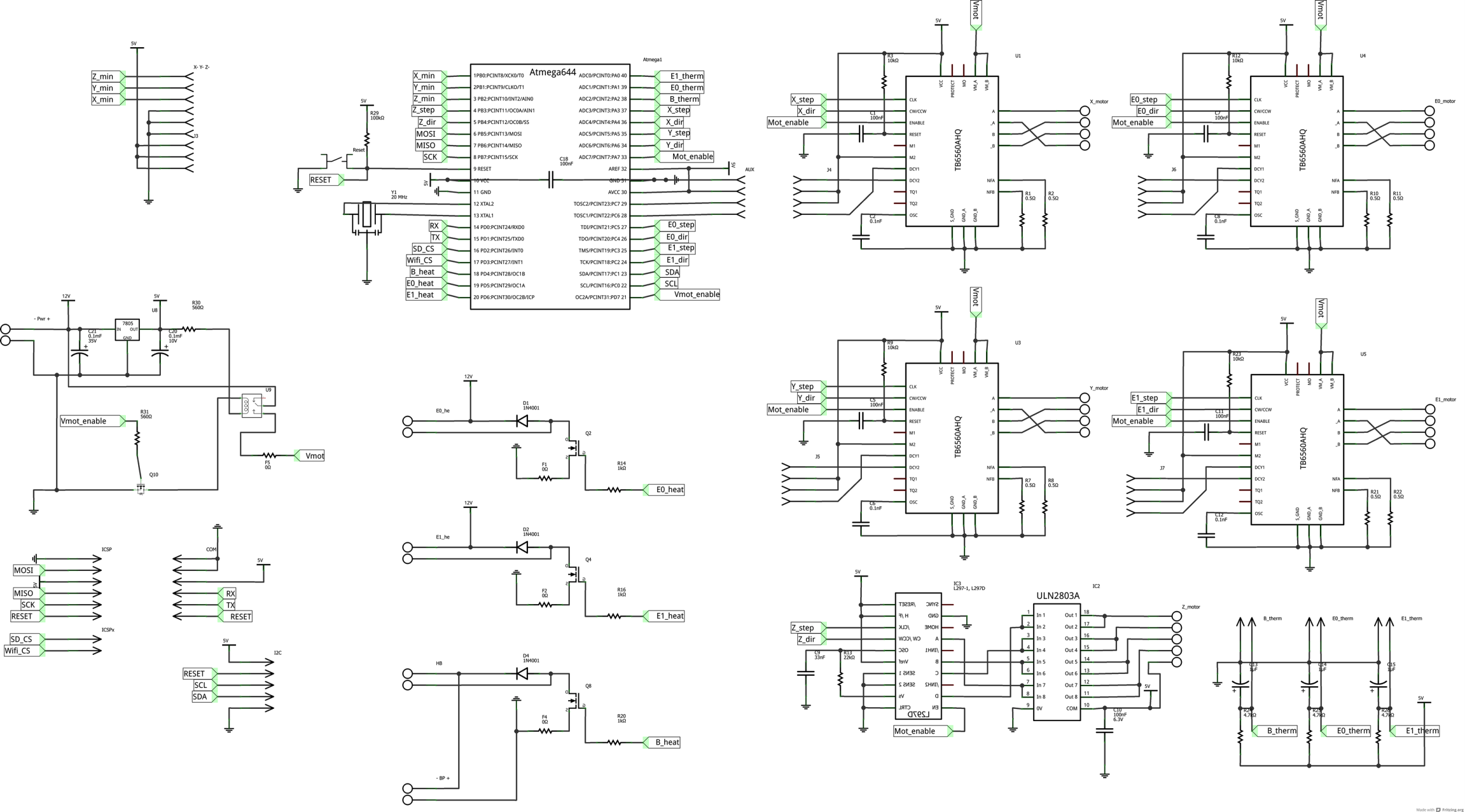
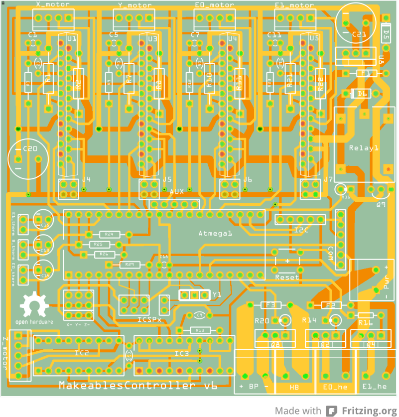
I have made a few updates to the board:
- The fuses are now in the positive line, this should improve safety. I have chosen to go for polyfuses, but I will test normal fuses in this design as well.
- The power tracks are made a lot thicker, the heated printbed should be able to get 16amp without burning the traces in the new design.
- The connectors are changed to 16amp types. This should prevent heat problems, and this is in line with the trace design!
- I have added Vmot (which is the power switched by the relay) to the AUX. In the future I will try to make this port useful as a fan-extender. A 7812 and two transistors should make a nice dual fan-output on this port.
Thanks for the feedback! I'll keep working on it as soon as more issues arise, so feedback is still more than welcome!
Edited 1 time(s). Last edit at 12/01/2013 04:57PM by vajpeters.
|
Re: Dual extrusion TB6560 controller December 03, 2013 12:18PM |
Registered: 10 years ago Posts: 12 |
|
Re: Dual extrusion TB6560 controller December 03, 2013 03:50PM |
Registered: 11 years ago Posts: 33 |
That's a good point, but these chips are a bit more expensive and a lot harder to source. The focus point of this controller is it's commenly available components at the lowest possible cost. I really try to push the limits of price/functionality for a dual extruder controller board...
What interests me is the second point you make: the TB6560 missing steps. Is that because of the pulse width in the current firmware/controller setup? Or due to torque issues?
What interests me is the second point you make: the TB6560 missing steps. Is that because of the pulse width in the current firmware/controller setup? Or due to torque issues?
|
Re: Dual extrusion TB6560 controller December 03, 2013 09:11PM |
Registered: 10 years ago Posts: 1,433 |
|
Re: Dual extrusion TB6560 controller December 04, 2013 04:00AM |
Registered: 10 years ago Posts: 12 |
I did try two of four axis driver board TB6560, both chinese made, one is generic design. It is OK when running slow speed using in CNC router in Marh3, but using in the 3D printer, 20mm/sec will missing steps all the time. Another TB6560 board is custom made, running 45mm/sec sometime will getting same result. I using the Marlin firmware, try to change the stepper.cpp but no luck.
What I guess is the clock speed limitation. TB6560 is 15khz, THB6064 is 200khz. After I changed to THB6064, all problem gone, pls let me know if you can make it work.
What I guess is the clock speed limitation. TB6560 is 15khz, THB6064 is 200khz. After I changed to THB6064, all problem gone, pls let me know if you can make it work.
|
Re: Dual extrusion TB6560 controller December 05, 2013 12:35PM |
Registered: 11 years ago Posts: 33 |
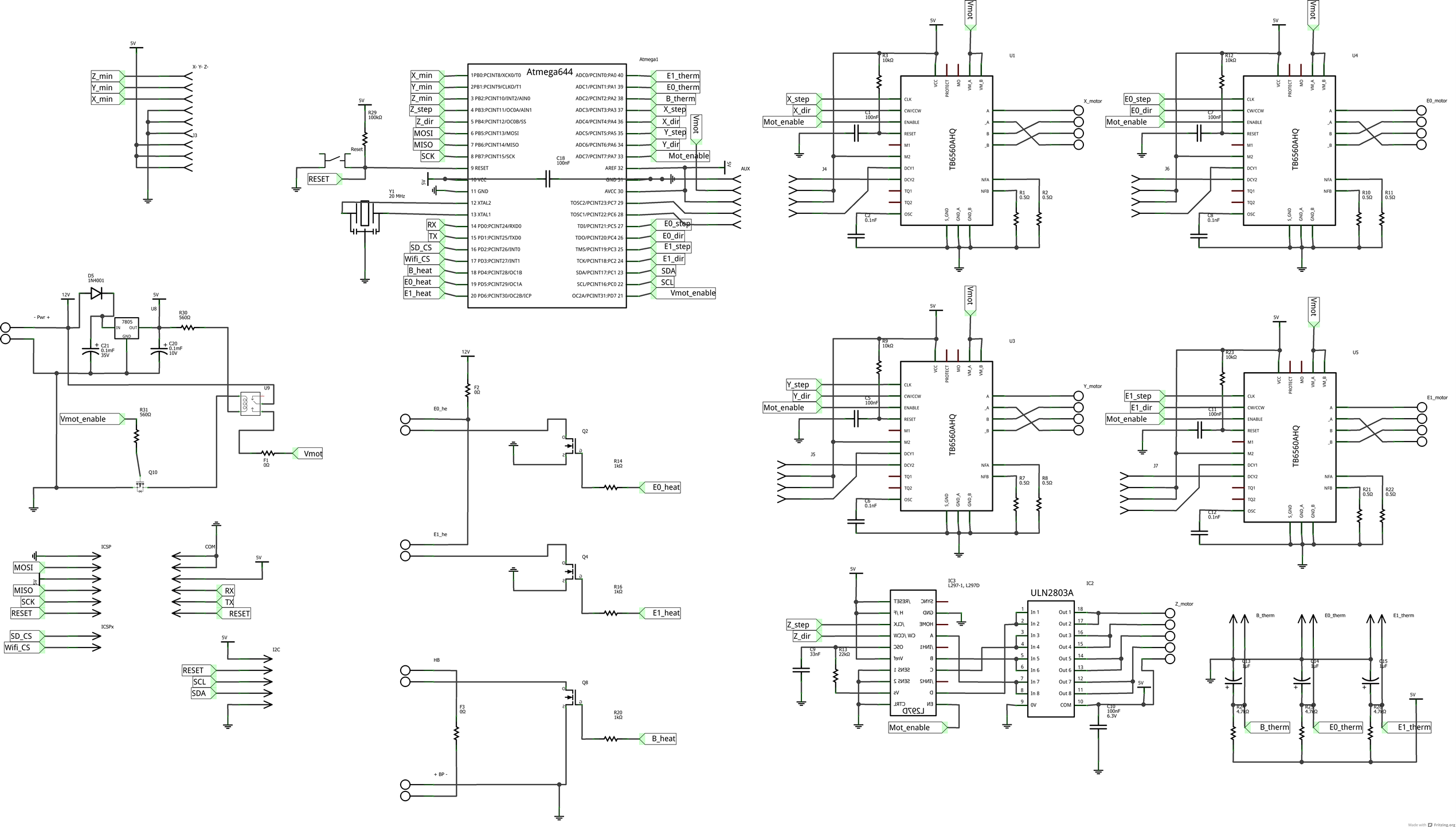
So here it is, version 7. The changes I made are minor:
- I changed for T73 relays because they are the cheapest available relays for the current needed.
- I cleaned up and widened some traces to prevent the board from failing on high currents.
- Changed to transistor instead of MOSFET activation for the relay
Can all of you check this one last time? Then I will make another 10 proto's...
|
Re: Dual extrusion TB6560 controller December 05, 2013 01:34PM |
Registered: 10 years ago Posts: 1,433 |
|
Re: Dual extrusion TB6560 controller December 05, 2013 02:04PM |
Registered: 11 years ago Posts: 33 |
The relay is for powering up the TB6560's. The 1N4001 is for protecting the transistor driving the coil. Isn't this right?
And is the diode configuration in my v4 scheme okay to protect the MOSFETS? I see in the RAMPS and Sanguinololu that it could also be solved with a 10k resistor, which could be cheaper. Is that also sufficient?
Edited 1 time(s). Last edit at 12/05/2013 02:45PM by vajpeters.
And is the diode configuration in my v4 scheme okay to protect the MOSFETS? I see in the RAMPS and Sanguinololu that it could also be solved with a 10k resistor, which could be cheaper. Is that also sufficient?
Edited 1 time(s). Last edit at 12/05/2013 02:45PM by vajpeters.
|
Re: Dual extrusion TB6560 controller December 05, 2013 07:22PM |
Registered: 10 years ago Posts: 1,433 |
The diode on the mosfet does a couple of things, both of them good. It takes care of ESD and it acts as an inductive load clamp. It does a much better job than other approaches. The diode costs a cent to a few cents. The resistor costs a fraction of a cent. Either way it's not a cost driver in the design.
If the relay is powering up your stepper drivers, then a 1 A relay isn't going to be enough. The diode across the relay is to protect the transistor. As soon as somebody decides to attach a relay to one of your mosfets, you get the same sort of spike / same problem / same solution. Even a "resistive" heater may be quite inductive at the speed the feet's may be switching.
If the relay is powering up your stepper drivers, then a 1 A relay isn't going to be enough. The diode across the relay is to protect the transistor. As soon as somebody decides to attach a relay to one of your mosfets, you get the same sort of spike / same problem / same solution. Even a "resistive" heater may be quite inductive at the speed the feet's may be switching.
|
Re: Dual extrusion TB6560 controller January 25, 2014 01:00PM |
Registered: 11 years ago Posts: 33 |
I have made a prototype, but my TB6560 seems to be running hot without moving a stepper motor. What can it be? All other functions are working properly with Repetier, but these TB6560 are a lot more difficult to work with! Does anyone have a suggestion where to look? I have checked my PCB for soldering mistakes, but the PCB is nice and tidy. And the schematic also doesn't show any mistakes as far as I can tell. The strangest thing is that the driver is also heating up when there is only voltage applied to the signal side, so before VMA and VMB are switched on.
Eppur si muove!
Eppur si muove!
|
Re: Dual extrusion TB6560 controller January 28, 2014 10:26AM |
Registered: 13 years ago Posts: 632 |
|
Re: Dual extrusion TB6560 controller February 28, 2014 05:51PM |
Registered: 11 years ago Posts: 33 |
Found it! And none of the suggestions helped. It drove me quite crazy. And then I discovered somebody else with similar problems: [giantpong.wordpress.com]. And it gave me a clue. But what caused it?
Actually I was punished for being greedy. I bought 5 TB6560AHQ’s from eBay (from GC_Supermarket). After reading the website above, I checked all my TB6560AHQ’s. They all gave a zero ohm reading between pin 1 and 17. Something which isn’t possible with genuine parts. (Always check the data sheet!)
After my discovery I bought 5 pcs from greenhouse408 on eBay. Directly after buying, I checked the pin 1/pin 17 reading, and it showed nearly unlimited resistance. Got it! Genuine TB6560AHQ’s!
Now I can finally continue testing my board! In the mean time I made the board a little more rugged, by adding some very cheap decoupling capacitors and some other stability stuff (connections to earth of unused connections etc.).
Eppur si muove!
Sorry, only registered users may post in this forum.