DIY Power Supply?
Posted by zipmsp
|
DIY Power Supply? March 08, 2014 10:59PM |
Registered: 10 years ago Posts: 8 |
I am building a 3D printer as a way to learn more about electronics. Most plans use the 12VDC rails of an ATX power supply. Since I am not in a hurry and would like to learn and apply electronic concepts, I plan to build my own power supply. I can build a 120VAC->{1.2 to 32}VDC power supply with a step-down transformer, full-wave bridge rectifier (diodes), a filter (big capacitor), and a rectifier (eg LM338 with potentiometer and heat sink). It seems like ATX power supplies are much more complicated than this. There are extra transformers, ICs, and bifilar inductor(s). Are these other components necessary?
|
Re: DIY Power Supply? March 09, 2014 01:26AM |
Registered: 14 years ago Posts: 1,092 |
The one thing that an ATX PSU has over the basic design that you're looking at is AC-DC conversion efficiency. Switch mode supplies, such as an ATX supply, can be very efficient (>90%, depends on design), whereas your more traditional PSU will most likely be well below that.
Also, unless you have a decent transformer on hand, you may find that your PSU will end up costing a whole lot more.
That said, those basic designs do work. Given the current you need to pull though, you want to be sure you've got enough filter capacitance to be able to supply the current between the full-wave peaks you'll get out of the transformer at 60 Hz (since you mentioned 120V, this most likely means you're in a country using 60 Hz).
PS: The other reason is that not everyone is good at electronics, and the last thing we want to do is have someone playing with >100V and getting themselves electrocuted.
|
Re: DIY Power Supply? March 09, 2014 01:26AM |
Registered: 13 years ago Posts: 1,352 |
For ac, if you have say mains input, 230v or 115v and want to get an output of say 12vac, then you use a transformer and transformers can be very efficient, like 97-98% which is awesome. And even there is some regulation imposed on the minimum efficiency of transformers, tho i forgot details on that. To scale ac down or up, transformer is a great tool, but its expensive and heavy. Then you convert the ac to dc, and that is also efficient, no significant losses, the diodes will loose a little but capacitors will not. At this point the system still has awesome efficiency, but this point onwards its dc current.
For dc, if you have 12v input and you want to get 5v output with 1A consumption, you will have to dissipate as heat the difference of 7V * 1A, e.g. 7 watts. For the values mentioned, we waste more than we use. This is what LM338 is doing, so depending on input and output, the efficiency can sometimes be terrible. Its a linear regulator, good ripple control, but losses ca not be controlled.
This is where smps comes into play. To get 5v from 12v, the switchmode regulator will keep interrupting the voltage with a duty cycle D. The energy released in the on cycle gets stored and released in energy devices which are inductors and capacitors. And the amazing trick is that inductors and capacitors have zero losses so the system is basically quite efficient especially across big differentials. Because input is on for D time and its off for (1-D) time, the output will average down to less value than input, according to the duty cycle D. Turning input on and off and have energy stored and released all the time is brutal behaviour, so even if there will be good capacitors on output, the ripple cannot be as good a linear ones. But the losses can be controlled, e.g. it is possible to see where losses come from and can take appropriate measures to reduce those losses. Sometimes depends on operating frequency or switch implementation chosen, there are trade-offs to do, but things are quite manageable.
The computer ATX psu (power supply) is a smps (switched mode power supply), from mains power down to its outputs. First, it rectifies the ac input to dc directly, like 300vdc and then scales that down to 12v, even multiple outputs, and does that with some efficiency in the range of typically say ~75-85%, and provides tens of amps at that value, which is quite amazing. Compare that to a regulator approach which if we want 12v@1a, the linear regulator would have to dissipate heat for the entire difference of 288v@1A, which is to say not really feasable. We cant get around with dissipating 288watts for each amp we want at 12v. That is the role of smps supply and why it is necessary.
If you want to build your own psu that is great. Easy diy, if you have an dead or defective UPS unit you can use that transformer, with that case, slap a diode bridge and some caps, and after caps feed directly to steppers, maybe to hotend and perhaps even to hot bed (if trafo is powerful enough, but probably wont be). The if you want a regulated 12v, perhaps for supply of uC, then you can use a LM338 or equivalent and even if its linear it will only have to provide a small amount of amps so it wont dissipate much. As long as most power is drawn right after the filter capacitors, and only a fraction passes through LM338, then it would be easy to get efficiency even higher than of a smps. I think its a great starting project to do and can learn quite alot from it. Have fun.
|
Re: DIY Power Supply? March 09, 2014 01:31AM |
Registered: 13 years ago Posts: 1,352 |
 Good morning btw
 |
Re: DIY Power Supply? March 09, 2014 12:04PM |
Registered: 10 years ago Posts: 8 |
|
Re: DIY Power Supply? March 12, 2014 06:34PM |
Registered: 10 years ago Posts: 14 |
One good way to go may be using a fairly large toroidal transformer.. something like this:
[www.mouser.com]
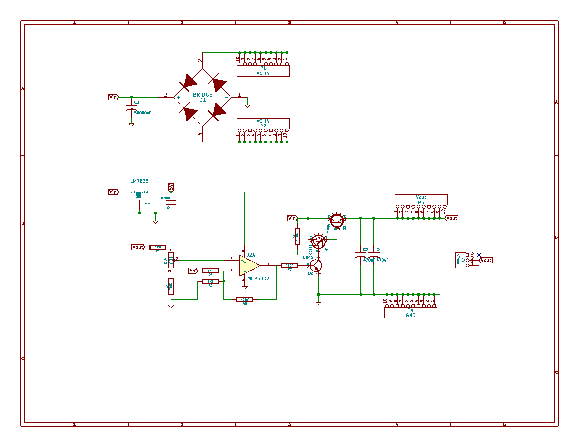
followed by a bridge rectifier and large capacitor. After this basic circuit, you can build your own regulation circuit with 3 transistors, an op amp, voltage regulator (for op amp), and some passives (I attached a circuit that has worked well for me). You can output much greater current than using LM338s. Technically you can parallel LM338s to increase the current capabilities, but I have found this is much more difficult in practice than just building your own regulator circuit with a beefy power transistor.
One thing you should be aware of is that a 12V rated output transformer when hooked up to a bridge rectifier/capactor will be more like 17V when unloaded and will approach 12V as you increase the load. Also, when you increase the load, unless you are using huge capacitors, you will start to get a 120hz ripple (if using 60hz AC). This may or may not be a problem, but you should be aware of it.
The circuit I attached would be good for you if you plan on running a fixed voltage that is close to the transformer rated voltage. The output voltage is adjustable, but may be impractical to run too low of voltage at high power. You will dissipate heat relative to your dropout voltage, but the good thing is that the dropout voltage decreases as the load increases. For example, let's say you are pulling 1 amp at 12 volts and at this load, the output of your bridge rectifier/filter circuit (input to regulator circuit) is 17V.. In this scenario, you would be dissipating 5 Watts ((17v-12v) * 1a = 5w) of heat. Then let's say you pull 10 amps again at 12 volts. At this load you wouldn't be dissipating 50 Watts ((17v-12v) * 10a = 50w) of heat. Instead, the bridge rectifier/filter circuit would be outputting more like 14 volts, which translates to dissipating 20 Watts ((14v-12v) * 10a = 20w) of heat.
One good thing is that the output voltage is SUPER clean and it is a relatively simple and robust circuit. It is also really quiet (no switching noises). The negative is that it is expensive and it might not be powerful enough to run your whole 3D printer (depends on your heated bed situation). The transformer is about $80 and the large capacitor is around $10, but one would say that the education gained from such a project is.. priceless..
[www.mouser.com]
followed by a bridge rectifier and large capacitor. After this basic circuit, you can build your own regulation circuit with 3 transistors, an op amp, voltage regulator (for op amp), and some passives (I attached a circuit that has worked well for me). You can output much greater current than using LM338s. Technically you can parallel LM338s to increase the current capabilities, but I have found this is much more difficult in practice than just building your own regulator circuit with a beefy power transistor.
One thing you should be aware of is that a 12V rated output transformer when hooked up to a bridge rectifier/capactor will be more like 17V when unloaded and will approach 12V as you increase the load. Also, when you increase the load, unless you are using huge capacitors, you will start to get a 120hz ripple (if using 60hz AC). This may or may not be a problem, but you should be aware of it.
The circuit I attached would be good for you if you plan on running a fixed voltage that is close to the transformer rated voltage. The output voltage is adjustable, but may be impractical to run too low of voltage at high power. You will dissipate heat relative to your dropout voltage, but the good thing is that the dropout voltage decreases as the load increases. For example, let's say you are pulling 1 amp at 12 volts and at this load, the output of your bridge rectifier/filter circuit (input to regulator circuit) is 17V.. In this scenario, you would be dissipating 5 Watts ((17v-12v) * 1a = 5w) of heat. Then let's say you pull 10 amps again at 12 volts. At this load you wouldn't be dissipating 50 Watts ((17v-12v) * 10a = 50w) of heat. Instead, the bridge rectifier/filter circuit would be outputting more like 14 volts, which translates to dissipating 20 Watts ((14v-12v) * 10a = 20w) of heat.
One good thing is that the output voltage is SUPER clean and it is a relatively simple and robust circuit. It is also really quiet (no switching noises). The negative is that it is expensive and it might not be powerful enough to run your whole 3D printer (depends on your heated bed situation). The transformer is about $80 and the large capacitor is around $10, but one would say that the education gained from such a project is.. priceless..
|
Re: DIY Power Supply? March 15, 2014 01:35AM |
Registered: 10 years ago Posts: 8 |
MacSkyver, what did you use to draw that schematic? It looks professional. Thanks for the regulation circuit idea. I plan to look into that next.
I've been reading about voltage and amperage needs. Arduino MEGA operates on 5V and the recommended input voltage is 7-12V. Arduino's voltage regulator starts to overheat above 12V. Is the higher voltage output by an unloaded transformer going to fry the Arduino? RAMPS 1.4 can run on 12V and needs 5A for five steppers and two hot ends + 11A for heated bed. This number matches the MakerFarm Prusa 8" i3 minimum amperage of 16A.
I worked out an example of a linear regulated power supply. Start with a 120VAC to 16VAC transformer at 6.25A (187F16) connected to a full-wave bridge rectifier rated for 15A and a forward voltage drop of 0.67V (SBR15U100CTL-13). This leaves me with 15.33V. Add a 0.01F capacitor rated for 50V (ECO-S1HA103EA). Ripple is now I/CF= 5 A / (0.01F * 240hz) = 2V. Is this ripple acceptable? Add the LM338 linear regulator with resistors, protection diodes, output capacitors, and a fuse for the transformer. The regulator is rated for a maximum of 5A. I now have to power the heated bed separately. At 5A, the dropout voltage is about 2.75V. So I think I can expect to get 12.58V of regulated DC out of this power supply. The heat output of the regulator is (2.75V + 0.58V) * 5A = 16.65W. At R_thJA = 35C/W, that is a 583C increase in temperature. Which is well above the 125C long term stability temperature. Is it feasible to dissipate ~17 watts via a heatsink? Edit: Could the waste heat be used to heat a printer bed? Perhaps the regulator sits below a copper bed, or a heat pipe is used to transmit heat to a fixed-bed printer (delta-type).
I am starting to see why switching power supplies are superior to linear regulators. Especially at higher currents. Maybe I will build a small one as a bench power supply at low current.
Edited 2 time(s). Last edit at 03/15/2014 03:02AM by zipmsp.
|
Re: DIY Power Supply? March 15, 2014 04:29PM |
Registered: 10 years ago Posts: 14 |
The program I used to draw the schematic is Kicad. It is free and open source. I highly recommend it.
It's hard to say if the arduino voltage regulator would fry if hooked to an unloaded 12V transformer. It depends on how much current the arduino is using. The 16V transformer you listed would most likely burn the arduino voltage regulator as it's unloaded voltage would be around 23V and the max voltage for arduino is 20V. You could always run an intermediate voltage regulator just for the arduino.. like a 7812 or 7808 (12v or 8v preregulator).
With the example linear supply you listed, the ripple may be fine as long as the trough of the ripple doesn't drop below your output voltage plus your dropout voltage. The R_thJA = 35C/W you have listed is for the regulator with no heatsink. You would definitely need a heatsink.. Assuming you are using a TO-220 packaged LM338, the R_thJC is 4C/W. If you couple that with a decent heatsink that is say 3C/W, you can have 7C/W ish total.. So for 17W that is an increase of about 119C.. Still a little too much. I would also be a little leary of the 5A rating of the voltage regulator. Usually there is a catch or very specific conditions where the rating is applicable... like assuming an infinitely large heatsink or something like that. I think practically for voltage regulators, you should cut their rated current output in half as a general rule of thumb.
As far as the heated bed is concerned, I don't believe 17W is not enough heat to run one. Also, controlling the bed temperature would be a pain.
Yeah, using a switching power supply like a computer PSU or the chinese $30, 30 amp wonder off of amazon is much easier and simpler than building a linear PSU. It's still a good learning experience to build the linear variety though. If I were you, I would try to build the 5amp linear power supply that you have described above with a potentiometer to adjust full voltage range. Then hook up an oscilliscope lead to the output of the transformer/filter, and another lead to the output voltage, and play around with it, adjusting the loads and voltages. Maybe hook up a temperature sensor to the heat sink as well.
|
Re: DIY Power Supply? March 16, 2014 11:57PM |
Registered: 10 years ago Posts: 52 |
The ATX power supply is a good thing to use not only because they are cheap, easy to find and you can often get one from an old PC for free. But when using the RAMPS, if you hooked it up properly, the standby 5v(Usually Purple cable) will power the board and LCD even when the PSU is off. With the PS_ON(Green cable) hooked up, your power supply magically start at the beginning of a print, and shutdown at the end, leaving the electronics running.
I included a picture for those who don't know how, by the way, if you do that, don't forget to remove diode D1, there are two diode, the one you need to remove is the one under a pololu. After that you need to tell your firmware( i use Marlin) that it needs to power the PSU before the print, and stop it after. So in slic3r's printer settings(if you use slic3r), in custom G-code, add M80 at the Start, before G28, and M81, at the end, after M84. Save your defaults settings after that.
I use a power supply from an old Server, the 5V Standby is 2A on mine so, plenty of power, but most PSU have 500mA, which should be enough.
More Info on the Wiki I though that this info was hidden pretty well in there...
I thought about using a smaller PSU, and power the hotbed with an dimmable halogen lamp electronic transformer, it would be cool to adjust the voltage given to the heater instead of just on and off the relay, but then i thought, i still need the relay, can't power that bed all the time... And i already had that extra PSU... Maybe i'll try it on another build.
Edited 1 time(s). Last edit at 03/16/2014 11:59PM by swe3tdave.
I included a picture for those who don't know how, by the way, if you do that, don't forget to remove diode D1, there are two diode, the one you need to remove is the one under a pololu. After that you need to tell your firmware( i use Marlin) that it needs to power the PSU before the print, and stop it after. So in slic3r's printer settings(if you use slic3r), in custom G-code, add M80 at the Start, before G28, and M81, at the end, after M84. Save your defaults settings after that.
I use a power supply from an old Server, the 5V Standby is 2A on mine so, plenty of power, but most PSU have 500mA, which should be enough.
More Info on the Wiki I though that this info was hidden pretty well in there...
I thought about using a smaller PSU, and power the hotbed with an dimmable halogen lamp electronic transformer, it would be cool to adjust the voltage given to the heater instead of just on and off the relay, but then i thought, i still need the relay, can't power that bed all the time... And i already had that extra PSU... Maybe i'll try it on another build.

Edited 1 time(s). Last edit at 03/16/2014 11:59PM by swe3tdave.
|
Re: DIY Power Supply? March 17, 2014 06:59PM |
Registered: 10 years ago Posts: 8 |
Sorry, only registered users may post in this forum.