Gen3 electronics mod for Mendel
Posted by BalanceSeeker
|
Gen3 electronics mod for Mendel February 20, 2010 12:09PM |
Registered: 14 years ago Posts: 42 |
I am currently in the midst of battle to construct my Mendel. I have a question regarding the mods required for the Gen3 electronics.
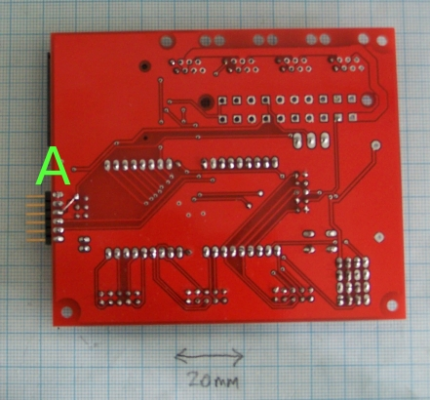
According to the RepRap site (http://dev.www.reprap.org/bin/view/Main/Motherboard_1_2), the following mod is necessary on the back of the motherboard PCB
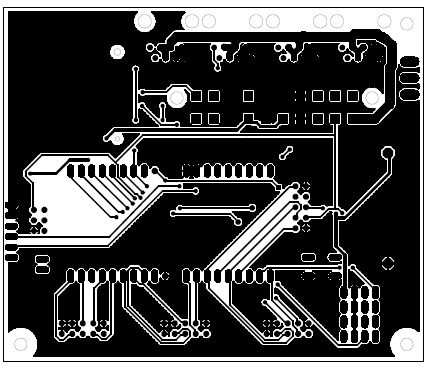
Please note the tracks that lead away from "A", and compare that with the image, provided in mother-board.zip file from source-forge. This is the image used for UV-exposure/toner-transfer.
These two images are not the same. So, I am faced with two possibilties:
1. Either the reprap website contains the incorrect image, in which case the procedure for Gen3 mod needs updating/correcting, OR
2. The PCB files in the motherboard zip file from sourceforge is wrong, in which case this needs to be updated to reflect the correct Gen3 update procedure.
Of course, there is always the third (unspoken) option: I am an idiot and have missed something totally obvious.....if that is the case, please do point it out to me, that I may hang my head in shame
Thankyou in advance,
Marius Botha
Pretoria, South Africa
[mariushermanbotha.wordpress.com]
According to the RepRap site (http://dev.www.reprap.org/bin/view/Main/Motherboard_1_2), the following mod is necessary on the back of the motherboard PCB
Please note the tracks that lead away from "A", and compare that with the image, provided in mother-board.zip file from source-forge. This is the image used for UV-exposure/toner-transfer.
These two images are not the same. So, I am faced with two possibilties:
1. Either the reprap website contains the incorrect image, in which case the procedure for Gen3 mod needs updating/correcting, OR
2. The PCB files in the motherboard zip file from sourceforge is wrong, in which case this needs to be updated to reflect the correct Gen3 update procedure.
Of course, there is always the third (unspoken) option: I am an idiot and have missed something totally obvious.....if that is the case, please do point it out to me, that I may hang my head in shame

Thankyou in advance,
Marius Botha
Pretoria, South Africa
[mariushermanbotha.wordpress.com]
|
Re: Gen3 electronics mod for Mendel February 20, 2010 02:06PM |
Registered: 16 years ago Posts: 536 |
|
Re: Gen3 electronics mod for Mendel February 20, 2010 02:19PM |
Registered: 14 years ago Posts: 42 |
LOL!
It is a bit like the game called, spot-the-difference.
Look at the tracks leading directly away from ICSP, and compare between images.
I think you will see what I mean.
At any rate, we must never rule out the "idiot" factor, LOL! I could still be mistaken.
But thankyou for your response. It is much appreciated.
Best,
Marius Botha
Pretoria, South Africa
[mariushermanbotha.wordpress.com]
It is a bit like the game called, spot-the-difference.

Look at the tracks leading directly away from ICSP, and compare between images.
I think you will see what I mean.
At any rate, we must never rule out the "idiot" factor, LOL! I could still be mistaken.
But thankyou for your response. It is much appreciated.
Best,
Marius Botha
Pretoria, South Africa
[mariushermanbotha.wordpress.com]
|
Re: Gen3 electronics mod for Mendel February 20, 2010 03:07PM |
Registered: 16 years ago Posts: 536 |
Ah, right! Now I see it - the top trace on the ICSP connector. Yeah, looks like they're different versions. Looking at the PDF's from subversion, I see that the photo with the A you've uploaded above is actually of the Motherboard v1.1. The toner-transfer image is v1.2, which is the latest. They probably wrote the docs with an earlier version, and didn't bother to update the photos.
I'm actually using v1.1 right now, I just tweaked the power control circuit a bit, but it works fine.
Wade
I'm actually using v1.1 right now, I just tweaked the power control circuit a bit, but it works fine.
Wade
|
Re: Gen3 electronics mod for Mendel February 20, 2010 03:12PM |
Registered: 15 years ago Posts: 132 |
Subtle difference. The ground fill and routing around the SD card is at issue. This should not affect the mod. Probably the film version was made with sangino routing. electrically they look the same.
Basically what the mod is providing is power through the board. The ISP header is a convenient place to inject 5 volts from the USB cable. Some of the ATMEL tools such as the STK500 do this.
Since the pins on the headers are the same, the mod is the same.
-julie
Basically what the mod is providing is power through the board. The ISP header is a convenient place to inject 5 volts from the USB cable. Some of the ATMEL tools such as the STK500 do this.
Since the pins on the headers are the same, the mod is the same.
-julie
|
Re: Gen3 electronics mod for Mendel February 21, 2010 06:48AM |
Registered: 14 years ago Posts: 42 |
Hello julie,
After several years of not having had "hands-on" experience with electronics, one loses touch with the "general rules of thumb" that apply to various technology families. I, therefore, hope you do not mind me seeking clarity from some of your previous comments.
Your comment:
..."The ground fill and routing around the SD card is at issue."..
I have no idea what you mean, here. Could you please elaborate?
Your comments:
... "electrically they look the same.
Basically what the mod is providing is power through the board. The ISP header is a convenient place to inject 5 volts from the USB cable"...
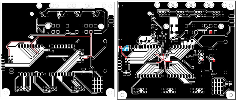
I accept that, in principle, the mod provides the 5v power rail to the board. However, I have traced my own board (with the above-mentioned mod), and find that not all components are in electrical contact with the power rail. See picture below:
I have high-lighted the 5V power rail in red. The mod is basically applied at the bottom of the PCB, which is the image on the left. The image on the right-hand-side, is the component side of the PCB. Again, here the 5v rail is denoted in red.
From the component-side, it is quite clear to me that the 5v rail reaches the CPU. Indeed, it is the same rail that I used to successfully bootload the Atmega644p.
However, the R2 resistor does not seem to be in electrical contact with the 5v rail. This resistor feeds the "power" LED. The place where the R2 resistor is placed on the PCB, is high-lighted in light-blue.
According to the schematic, the R2 resistor goes directly to 5v. However, this does not seem to be the case:
1. either by continuity testing with multimeter, or
2. visual inspection of the PCB layout.
I will be most sincerel endebted to anyone who can point out the error I have made.
Thankyou, in advance
Marius Botha
Pretoria, South Africa
[mariushermanbotha.wordpress.com]
|
Re: Gen3 electronics mod for Mendel February 21, 2010 06:20PM |
Registered: 15 years ago Posts: 132 |
I think I see some of the confusion now. I have the 20091007 version of the eagle layout on my computer. I was going to etch this myself, but noticed that makerbot had blanks in stock, so ordered one last week.
Looking at the highlighted lines in Eagle, I see several different power buses. The schematic reflects the ATX supply version.
The modification takes 5 volts from the USB header on what is noted as an unused pin. This power does not have a net name and is not on the schematic.
R2 gets power from the ATX header. This net is called VCC. There is also a net named 5VSB sourced on the ATX header. These nets are not connected. If you look at the wiki assembly page it can be seen that there are more modifications to the ATX header to connect these nets.
The ATX supply has a method where a small bit of power wakes up the rest of the supply. There are also critical timings as to the order the different power buses turn on. This is so one can press a power switch or keyboard key and turn the computer on.
Note, that SD cards are not 5V tolerant. So there is a set of level shifting resistors used to connect the SD card to the ISP pins. If you plan to use SD, then you will need an additional 3.3volt supply.
Sorry for any confusion on this issue. Hopefully the wiki page will help make things more understandable.
In relation to the first observation regarding the ground fill. This was indicating how the eagle layout editor draws the filled planes and keepout areas. I was noting that was the subtle difference in the first post and hard to see. It may also seem confusing as two different people answered at the same time.
-julie
|
Re: Gen3 electronics mod for Mendel May 24, 2010 04:09PM |
Registered: 15 years ago Posts: 478 |
Interesting post..
I also ordered and received a "motherboard 1.2" from Makerbot in February.
Closer inspection.. reveals that despite ordering the 1.2 motherboard and the packing note indicating it was a 1.2 version.
I actually received the 1.1 version of the Motherboard which has the older track layout .
As I escaped any extra handling chages from the post Office on this order I did not send it back.
So it could be possible that you recived the "old 1.1 version" like I did due to Stock confusion at Makerbot.
Bodge It [reprap.org]
=======================================
My rep strap: [repstrapbertha.blogspot.com]
Buy the bits from B&Q pipestrap [diyrepstrap.blogspot.com]
How to Build a Darwin without any Rep Rap Parts [repstrapdarwin.blogspot.com]
Web Site [www.takeaway3dtech.com]
|
Re: Gen3 electronics mod for Mendel July 06, 2010 10:00PM |
Sorry, only registered users may post in this forum.


