Help Wiring Large (12"x12") Heatbed Through Relay or MOSFET
Posted by TheSerialHobbyist
|
Help Wiring Large (12"x12") Heatbed Through Relay or MOSFET June 17, 2014 04:31PM |
Registered: 9 years ago Posts: 36 |
Hey guys!
So I'm building a DIY Taz, and I'm trying to figure out how to properly hookup the heatbed to the RAMPS 1.4 board.
The heatbed is 12"x12" and 12V, and it will be connected to a regular RAMPS 1.4 board. The power supply is 12V, 360W, 30A.
I've read that the RAMPS board can't supply the necessary current to run the heatbed (supposedly at least 15A), and that I need to wire it via a relay.
However, I've also read that a mechanical relay can't keep up with the PWM needed for PID control (or that it won't last). Solid state relays may or may not be able to handle it, but they're expensive.
So, I saw that I should instead use a MOSFET. But I'm a little confused about what MOSFET to buy, and how it should be wired. Can you guys help me out with that?
|
Re: Help Wiring Large (12"x12") Heatbed Through Relay or MOSFET June 17, 2014 06:47PM |
Registered: 13 years ago Posts: 1,352 |
What kind of bed is that? Try using a multimeter to check its resistance. Only after that you can figure out how much current it will draw when supplied with 12v. For example if it has 0.9 ohms, it will draw 12v/0.9ohms = 13.33amps. If it draws less than 10amps, you should be safe. But anyway, where did u read the ramps cant handle the bed current. First find out exactly how much current your bed wants, and then you can figure what to do.
The load (bed) is supplied hardwired with 12v. The mosfet switches its ground, hence this setup is called "low-side switching".
The mosfet has 3 terminals:
- one is named Gate, and this one is connected to the uC pin;
- other terminal is Drain, and this connects to the gnd side of the bed;
- the last is named Source and this one is connected to psu gnd.
When the uC outputs 5v on the gate pin, the mosfet will conduct current from drain to source. Meaning it will connect the bed gnd side to the psu gnd so the current will flow through the bed. Other than that, the bed is always connected to +12v, but if the gnd is disconnected the current cant flow anywhere. So its only the gnd that switches.
|
Re: Help Wiring Large (12"x12") Heatbed Through Relay or MOSFET June 17, 2014 09:22PM |
Registered: 9 years ago Posts: 36 |
Thanks for the reply!
This is the board I ordered: [www.ebay.com]
I haven't received it yet, but I'll measure the resistance when I get it. But the add says I'll probably need a relay (and I've read that elsewhere for large boards).
So what's limiting the current on the RAMPS 1.4 board to 10A? Is it just the MOSFET that's built into the board that can't handle more than 10A? If so, maybe I can just desolder that one and replace it with one that can handle the current of the large heatbed?
Or I can just make a simple circuit with high-current MOSFET using the output from the RAMPS board? MOSFETS are cheap, so I went ahead and ordered a couple of high-current MOSFETs (in N and P types), but I'm still not sure exactly how I should wire it.
|
Re: Help Wiring Large (12"x12") Heatbed Through Relay or MOSFET June 17, 2014 11:50PM |
Registered: 13 years ago Posts: 1,352 |
The mosfet itself probably can handle that, but the ramps has a series PTC fuse that is set ok up to 11A, you need to avoid that fuse. Also the pcb tracks are sort of small and long, especially the gnd track. So either take a thick copper wire to back those tracks, or desolder the mosfet and mount it on a separate heatsink, and just solder the wires directly to its terminals. I would choose to desolder the mosfet and mount it separately. But you probably dont need to buy another mosfet, unless that one burns.
You can read the datasheet and identify which pin is what, from the names above, gate, drain and source. Then you can wire it accordingly. The only thing you need from the ramps board is the gate line, and you solder one wire from the gate location of the old mosfet to the gate of the mosfet to be used. And use heat shrink tubing for isolation. Also the tab (the backing of the mosfet) the place where it screws in a piece of metal sheet, that is also connected to some of the wires, read datasheet to see which one, and be carefuly not to shortcircuit the heatsink to another voltage. Anyhow desolder the old mosfet to avoid having two gates tied to same pin, which would increase the capacitance and slower the gate rise time.
You can read the datasheet and identify which pin is what, from the names above, gate, drain and source. Then you can wire it accordingly. The only thing you need from the ramps board is the gate line, and you solder one wire from the gate location of the old mosfet to the gate of the mosfet to be used. And use heat shrink tubing for isolation. Also the tab (the backing of the mosfet) the place where it screws in a piece of metal sheet, that is also connected to some of the wires, read datasheet to see which one, and be carefuly not to shortcircuit the heatsink to another voltage. Anyhow desolder the old mosfet to avoid having two gates tied to same pin, which would increase the capacitance and slower the gate rise time.
|
Re: Help Wiring Large (12"x12") Heatbed Through Relay or MOSFET June 18, 2014 12:07AM |
Registered: 13 years ago Posts: 1,352 |
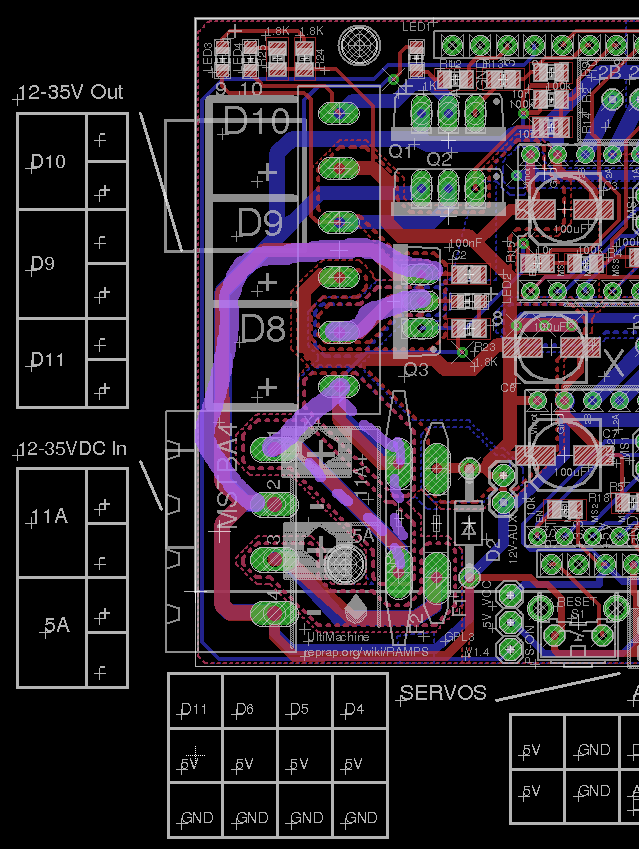
If you want to use the mosfet in place and reinforce the tracks, i attached a picture which shows 2 tracks to reinforce to the mosfet terminals. It should be done with a solid core copper wire, diameter like ~1,5-2mm, preferably isolated on the length.
Also there is a 3rd, a shortcut between two connectors to bypass the 11A PTC. But instead of doing that last shortcut between connectors, you can also choose to simply solder the wires that would be otherwise placed in those connectors. Those two wires do not go anywhere else, the only purpose was to have them through the fuse, but since you want to bypass the fuse its simpler to just solder the wires externally. You will need a soldering tool either way.
Good luck.
Edited 2 time(s). Last edit at 06/18/2014 12:13AM by NoobMan.
|
Re: Help Wiring Large (12"x12") Heatbed Through Relay or MOSFET June 18, 2014 11:08AM |
Registered: 9 years ago Posts: 36 |
Thanks for that thorough explanation! Unfortunately, I'm still not following 100%.
I had already ordered this MOSFET:
[www.sparkfun.com]
I'm pretty sure that one should be able to handle the current and voltage with no problems.
When I ordered it, I was planning on using the heatbed output from the board as the gate for a circuit like this:
[www.electronics-tutorials.ws]
Obviously the motor stuff would be replaced with the heatbed.
But you're saying having the onboard MOSFET feeding the new MOSFET like that wouldn't work well because it'd be slow?
I would prefer not to try to reinforce the traces. I can do basic soldering, but I'm not particularly skilled and don't want to screw up the board. Could I do something like on the attached drawing?
Basically what I'm thinking is:
Would that work?
Edit: I think I actually accidentally reversed + and - on that drawing, it looks like it's negative that goes through the MOSFET? Does that mean I need a P-type MOSFET or an N-type MOSFET? Luckily I ordered both, so I can use either one.
Edited 1 time(s). Last edit at 06/18/2014 12:04PM by TheSerialHobbyist.
I had already ordered this MOSFET:
[www.sparkfun.com]
I'm pretty sure that one should be able to handle the current and voltage with no problems.
When I ordered it, I was planning on using the heatbed output from the board as the gate for a circuit like this:
[www.electronics-tutorials.ws]
Obviously the motor stuff would be replaced with the heatbed.
But you're saying having the onboard MOSFET feeding the new MOSFET like that wouldn't work well because it'd be slow?
I would prefer not to try to reinforce the traces. I can do basic soldering, but I'm not particularly skilled and don't want to screw up the board. Could I do something like on the attached drawing?

Basically what I'm thinking is:
- Remove the current MOSFET
- Solder lead from the Gate trace to the new MOSFET Gate
- Solder trace from + terminal to MOSFET source
- Solder trace from MOSFET drain to heatbed
- Solder trace from - terminal to heatbed
Would that work?
Edit: I think I actually accidentally reversed + and - on that drawing, it looks like it's negative that goes through the MOSFET? Does that mean I need a P-type MOSFET or an N-type MOSFET? Luckily I ordered both, so I can use either one.
Edited 1 time(s). Last edit at 06/18/2014 12:04PM by TheSerialHobbyist.
|
Re: Help Wiring Large (12"x12") Heatbed Through Relay or MOSFET June 18, 2014 12:32PM |
Registered: 9 years ago Posts: 36 |

|
Re: Help Wiring Large (12"x12") Heatbed Through Relay or MOSFET June 18, 2014 01:28PM |
Registered: 13 years ago Posts: 1,352 |
First, yes to the yellow things, that is the existing ptc fuse, and that is the existing mosfet gate pin.
The white mosfet and orange lines seems ok as long as gate drain and source pins are correctly used, for which the datasheet reading is a must. What i did said is that if you use the mosfet externally, have to remove the one on the board. That is because each gate has a parasitic capacitance which should be as low as possible, and if the old fet remains in place its gate capacitance would just add to the external gate and would double the parasitic capacitance - and that is not beneficial.
Then if you use the mosfet externally, you have to desolder the existing one, and then you could just use the existing one externally. From sources it should be STP55NF06L, which looks bit better than the sparkfun one. If you have that or not on your board, dunno, i guess depends on who manufactured your board, if its a clone its possible that things may slightly differ than the source. If you want a better and safer mosfet that wont give problems you can try IPS1011, but it is going to be expensive.
About the schematic link you gave, from www.electronics-tutorials.ws, that is sort of the case, and Rg and R2 are already on the ramps board. In that schematic the motor has an inductive clamp, you can also add a recirculating diode on the terminals of your heated bed. That diode would be any diode, cheapest 1N400x but you can desolder a diode from (almost) any recycle bin junk, and you orient it with the arrow in the opposite direction of the current flow, that is the arrow goes from the bed - to the bed + terminal. Physically best placement is on the bed terminals, on the principle of solving the problem at its source instead of dealing with it further away.
About the rest, you just have to feed power to ramps through the lower connector, that goes through smaller ptc fuse (5A) and supplies everything else (except the bed).
I think you got it. Good luck
Edited 1 time(s). Last edit at 06/18/2014 01:32PM by NoobMan.
|
Re: Help Wiring Large (12"x12") Heatbed Through Relay or MOSFET June 18, 2014 01:45PM |
Registered: 9 years ago Posts: 36 |
Ah, okay, I see. So if STP55NF06L is the MOSFET on my board (it's an Ultimachine board, I'll check the MOSFET on it when I get home), then by far the easiest solution would be to:
Is that right? If so, that's pretty darn simple. Basically I'm using all of the stock onboard components, and just bypassing the 11A fuse, and adding a thick gauge wire in addition to the thin traces.
- Solder wire from + input terminal to + output terminal
- Solder wire going from - input terminal to onboard MOSFET source
- Solder wire going from MOSFET drain to - output terminal
Is that right? If so, that's pretty darn simple. Basically I'm using all of the stock onboard components, and just bypassing the 11A fuse, and adding a thick gauge wire in addition to the thin traces.
|
Re: Help Wiring Large (12"x12") Heatbed Through Relay or MOSFET June 18, 2014 02:40PM |
Registered: 13 years ago Posts: 1,352 |
Yes, this takes care of bypassing the 11amps ptc fuse. This is main thing to do.Quote
1. Solder wire from + input terminal to + output terminal
This becomes so that current comes in one connector, goes through board and exists the other connector, with no benefit, so if you have a soldering iron you can just solder those wires directly externally, and avoid the (+) connectors entirely.
Quote
2. Solder wire going from - input terminal to onboard MOSFET source
3. Solder wire going from MOSFET drain to - output terminal
Current direction through fet goes from drain to source, so the drain comes from bed - terminas. And source is permanently psu gnd. Coz i think you mixed the names there, but otherwise its ok.
So 2 and 3 is just if you want to reinforce the current paths and use the mosfet in the place that it is on the board. Imo there are two things to consider, current rating of connectors and that of tracks/polygons. Either way, high current would heat up the pcb area and connectors. In extremis would char the pcb with time. So if you just put a solid copper wire to improve the track then perhaps the track temp will be like -40C or even cooler, and that would help the connector to dissipate more, hence improve a tiny bit the effective rating of the connector aswell. As a note use a full solid core wire, if its multi-core on same diameter has less current rating, about half.
I wouldnt of trust a clone with cheapest pcb thickness and cheapest connectors to do that, but if you have an original UM board, you may idd give it a shot.
The external mosfet mounting was for the reason of avoiding tracks and connectors on the board. Your decision, either way.
Quote
Is that right? If so, that's pretty darn simple. Basically I'm using all of the stock onboard components, and just bypassing the 11A fuse, and adding a thick gauge wire in addition to the thin traces.
Yup, thats it really. Just a note about tracks or connectors heating up. First time use, let it run ~1 hour and then put the finger on connectors and pcb tracks. If they are cold enough you are good. If they get significantly hot then might need rewiring.
Edited 2 time(s). Last edit at 06/18/2014 02:46PM by NoobMan.
|
Re: Help Wiring Large (12"x12") Heatbed Through Relay or MOSFET June 18, 2014 03:00PM |
Registered: 9 years ago Posts: 36 |
Awesome, thank you!
You're right, there isn't any reason to solder a wire from the + terminal to the other + terminal. I think I'll just go ahead and use the wire for the - terminal > source pin and drain pin > negative, just in case. I'm not sure if those traces can handle the current, and it's pretty easy to add the wire. Should a 10AWG wire do the job?
You're right, there isn't any reason to solder a wire from the + terminal to the other + terminal. I think I'll just go ahead and use the wire for the - terminal > source pin and drain pin > negative, just in case. I'm not sure if those traces can handle the current, and it's pretty easy to add the wire. Should a 10AWG wire do the job?
|
Re: Help Wiring Large (12"x12") Heatbed Through Relay or MOSFET June 18, 2014 03:21PM |
Registered: 13 years ago Posts: 1,352 |
|
Re: Help Wiring Large (12"x12") Heatbed Through Relay or MOSFET June 18, 2014 03:40PM |
Registered: 9 years ago Posts: 36 |
|
Re: Help Wiring Large (12"x12") Heatbed Through Relay or MOSFET June 19, 2014 10:15AM |
Registered: 9 years ago Posts: 36 |
Fun new problem: I got the heatbed in last night and measured the resistance, and it's .4 ohms! At 12V, that's 30A/360W, which exactly what my power supply is rated for. Which means I need to add an additional power supply to power the board, steppers, hotend, etc. or find a more powerful power supply.
Edit: went ahead and ordered a ATX PSU that's 480W and can deliver 40A on the 12V rail, which I'll convert. Just need to return the old power supply.
Edited 1 time(s). Last edit at 06/19/2014 12:19PM by TheSerialHobbyist.
Edit: went ahead and ordered a ATX PSU that's 480W and can deliver 40A on the 12V rail, which I'll convert. Just need to return the old power supply.
Edited 1 time(s). Last edit at 06/19/2014 12:19PM by TheSerialHobbyist.
|
Re: Help Wiring Large (12"x12") Heatbed Through Relay or MOSFET June 19, 2014 03:54PM |
Registered: 13 years ago Posts: 1,352 |
Measuring resistances in that range could be kind of tricky, usually the low values are not read all that well and errors creep in. Depends on your multimeter and what errors/confidence it has.
But anyhow that .4 does not sound good. Short the probes together and see the probes resistance if it reads zero. For example if the shorted probes measure 0.2 then have to deduct that from the .4 reading.
On the plus side, if it the 0.4 reading is correct then its seems like a bed that would heat up pretty fast.
|
Re: Help Wiring Large (12"x12") Heatbed Through Relay or MOSFET June 19, 2014 06:24PM |
Registered: 9 years ago Posts: 36 |
Okay, I'll check that when I get home (shorting the probes). I mean, it's a pretty huge bed, and the description said it needed a lot of current, so I wasn't too surprised (I thought it would be 20-25A). Not a big deal though, I already ordered the ATX power supply, which I think will work better anyway.
|
Re: Help Wiring Large (12"x12") Heatbed Through Relay or MOSFET June 19, 2014 10:18PM |
Registered: 9 years ago Posts: 32 |
|
Re: Help Wiring Large (12"x12") Heatbed Through Relay or MOSFET June 20, 2014 10:38AM |
Registered: 9 years ago Posts: 36 |
|
Re: Help Wiring Large (12"x12") Heatbed Through Relay or MOSFET June 20, 2014 11:42AM |
Registered: 13 years ago Posts: 1,352 |
What i meant was to avoid paralleling the gates especially when one mosfet is not used.
Cascading power mosfets does not work, not like that, and on several considerations. On signal mosfets probably could use a pullup and would get an inverter. But these are not signal mosfets, these are power mosfets so trying to charge the gate with a pullup is not reasonable from my point of view. Anyway an inverter would not be good either, because it would mean that heater is on when the uC does not produce any signal, e.g. when uC is off, and that would be very dangerous.
Cascading power mosfets does not work, not like that, and on several considerations. On signal mosfets probably could use a pullup and would get an inverter. But these are not signal mosfets, these are power mosfets so trying to charge the gate with a pullup is not reasonable from my point of view. Anyway an inverter would not be good either, because it would mean that heater is on when the uC does not produce any signal, e.g. when uC is off, and that would be very dangerous.
|
Re: Help Wiring Large (12"x12") Heatbed Through Relay or MOSFET June 20, 2014 04:43PM |
Registered: 9 years ago Posts: 32 |
|
Re: Help Wiring Large (12"x12") Heatbed Through Relay or MOSFET June 20, 2014 04:47PM |
Registered: 9 years ago Posts: 36 |
|
Re: Help Wiring Large (12"x12") Heatbed Through Relay or MOSFET June 22, 2014 07:20AM |
Registered: 13 years ago Posts: 1,352 |
Do not use pwm for heated bed. I would certainly avoid doing that. When mosfet opens and closes, before reaching its end state (fully open), it goes through a state where its partially open and the difference that cant flow through has to be burned out in heat. At high currents of a power mosfet and a bed, that is going to be big. So better avoid having the mosfet through the transition zone as much as possible. So pwm-ing means you just abuse the mosfet making it go through transition zone a lot, repetitively. Even as that is just a relatively fast transition, a tiny fraction of time, because the current is high, the dissipation during that is again high, so overall becomes relevant. On a modern switched mode power supply the biggest losses are switching losses. Simple solution for us, just avoid pwm switching the bed because its not necessary. Bang-bang at full on and full off works fine.
|
Re: Help Wiring Large (12"x12") Heatbed Through Relay or MOSFET June 23, 2014 10:21AM |
Registered: 9 years ago Posts: 36 |
Sorry, only registered users may post in this forum.