Controller LCD contrast issue
Posted by drhender
|
Controller LCD contrast issue December 28, 2014 11:44PM |
Registered: 9 years ago Posts: 9 |
I am working on a new Prusa/Graber i3 printer, but am having an issue with the LCD.
Here's what I am using:
Arduino Mega 2560
Ramps 1.4
RepRapDiscount Full Graphics Smart Controller (previous edition w/ potentiometer and red PC
Marlin Firmware - Stable branch (downloaded this weekend)
I have been successful in building the Marlin firmware and downloading it to the Arduino. The controller boots up and the startup screen and then info screen display as expected, but I am having an issue with the contrast. The screen is almost entirely white, making it difficult to read. Looking at the display from an angle makes it readable, but obviously, I'd like to resolve the problem.
Changing the setting in the firmware's menu makes no difference. I've also changed the default value in the code and recompiled and downloaded it. The new default value shows up in the config menu, but the contrast is apparently the same.
I have also changed the potentiometer to see if that would effect the contrast, but the pot seems to make no difference at all. In fact, I even removed the pot from the board (desoldered it) and again, the contrast was identical.
Anyone have a suggestion as to what is going on?
I suspect one of the following:
* The Marlin firmware doesn't support the older version of the RepRapDiscount display board.
* The Display board is not functioning as expected
* There is something in the firmware code that I need to change to support the older board.
Any and all suggestions are welcome and appreciated!
-David.
Edited 1 time(s). Last edit at 12/28/2014 11:45PM by drhender.
|
Re: Controller LCD contrast issue December 29, 2014 12:45AM |
Registered: 9 years ago Posts: 590 |
I had a similar issue with my full graphic LCD controller, but I could not even see anything from any angle. I resolved the problem by adding a 270R resistor from the contrast signal (trimpot) to the 5V line. I connected the resistor between second and third of the empty pin holes as shown on the photo.
|
Re: Controller LCD contrast issue December 29, 2014 02:26AM |
Registered: 9 years ago Posts: 9 |
Tell me a little bit more... Once you had added the resister, did the trimpot or software setting allow you to further adjust the contrast? Did you have to cut any traces?
( I ask because I might wire up a new trimpot if the existing one doesn't work.)
BTW, how did you know to do that?
Thanks for the info!
( I ask because I might wire up a new trimpot if the existing one doesn't work.)
BTW, how did you know to do that?
Thanks for the info!
|
Re: Controller LCD contrast issue December 29, 2014 02:59AM |
Registered: 10 years ago Posts: 14,672 |
I have noticed that 12864 displays have a variety of options, determined by the presence or absence of components (including 0 ohm resistors) fitted to the board. There are some threads about this on the Displays section of the Arduino forum.
If the pot was fitted but not working, this suggests to me that there is a missing resistor on your board. Try following the PCB traces from the pot to see what they connect to. Posting a close up photo of the back of the display may get you some more help.
Large delta printer [miscsolutions.wordpress.com], E3D tool changer, Robotdigg SCARA printer, Crane Quad and Ormerod
Disclosure: I design Duet electronics and work on RepRapFirmware, [duet3d.com].
|
Re: Controller LCD contrast issue December 29, 2014 10:35AM |
Registered: 9 years ago Posts: 590 |
No, I did not have to cut any traces on the board. I checked the voltage on the trimpot and saw that it would not go above 1V, regardless of the setting of the trimpot. So I tried with various resistors between those pin holes (3k, 820R, 270R, just holding it
without soldering) to raise the voltage and then soldered the one which worked best...
without soldering) to raise the voltage and then soldered the one which worked best...
|
Re: Controller LCD contrast issue December 29, 2014 11:36AM |
Registered: 9 years ago Posts: 9 |
I soldered in a 270 ohm resister as you did, but it made no difference.
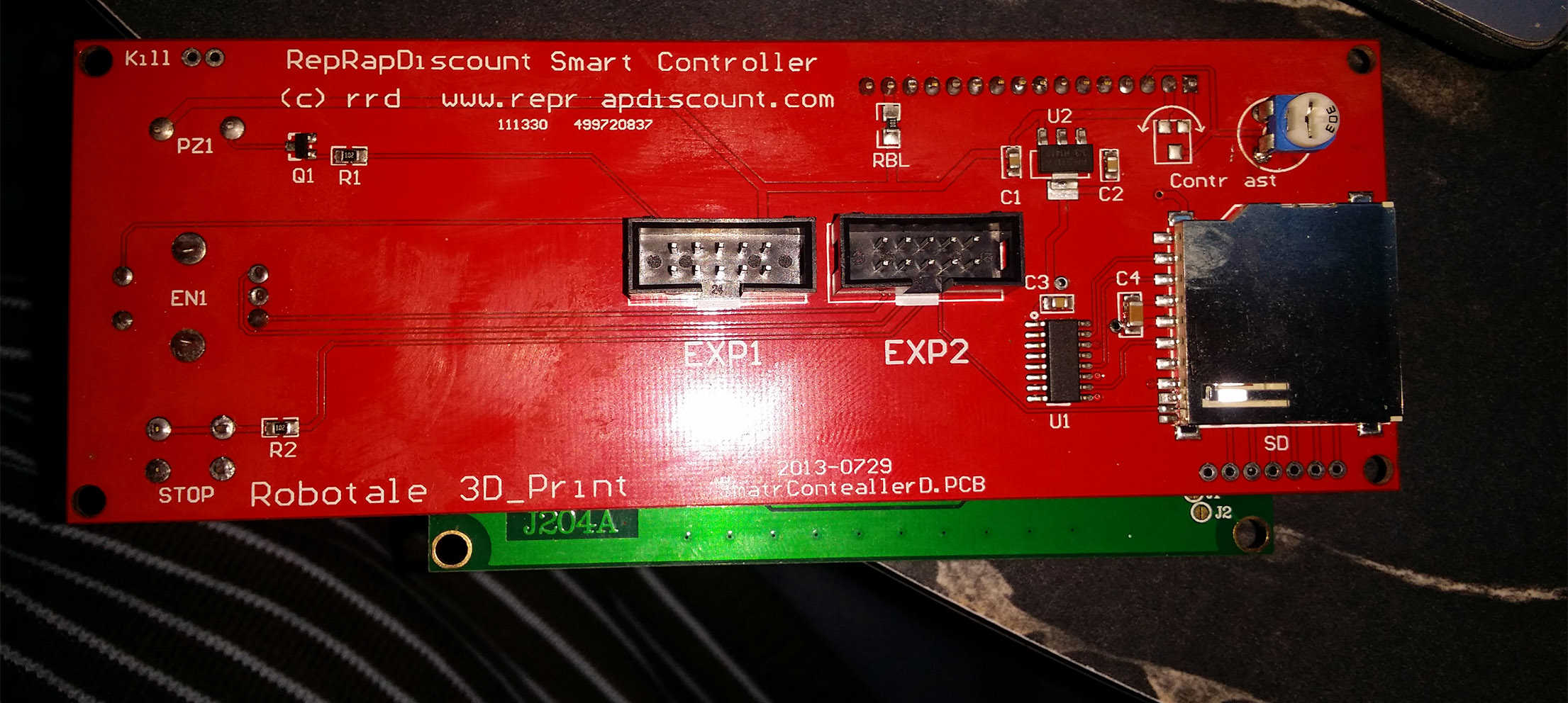
I am attaching a photo of my PCB as suggested by DC42-- it appears to be a similar board to yours. It appears that your board has a wider boarder than mine, but that may just be a difference in production runs.
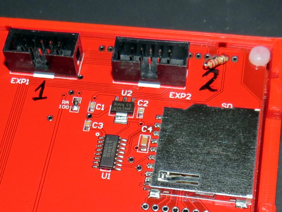
I am going to try different resisters as you suggest. I also notice that there is a pair of spots near the trimpot that appear to be for a surface-mount component. (See photo - marked RV, 3K) Is there anything soldered into place on your board in that location?
I am attaching a photo of my PCB as suggested by DC42-- it appears to be a similar board to yours. It appears that your board has a wider boarder than mine, but that may just be a difference in production runs.
I am going to try different resisters as you suggest. I also notice that there is a pair of spots near the trimpot that appear to be for a surface-mount component. (See photo - marked RV, 3K) Is there anything soldered into place on your board in that location?

|
Re: Controller LCD contrast issue December 29, 2014 12:07PM |
Registered: 9 years ago Posts: 590 |
|
Re: Controller LCD contrast issue December 29, 2014 07:02PM |
Registered: 9 years ago Posts: 9 |
After closer inspection, I realized that pins one and two were on the same trace. I confirmed this by removing power from the board and testing the resistance between the pins... there was no resistance. After powering back on,
I confirmed that 1 to ground and 2 to ground always showed a full 5VDC regardless of the position of the pot. So I cut the trace between them. After cutting the trace, the voltage on pin 2 ranges from 0 to 5V depending on position of the pot as expected.
But even after all of that, the display still has no contrast. I measured the voltage on pin 3 of the 12864-- the contrast control pin. That pin always shows 4.5VDC regardless of the voltage measurement on pin 2.
|
Re: Controller LCD contrast issue December 30, 2014 03:22AM |
Registered: 10 years ago Posts: 14,672 |
It was the back of the 12864 display that I wanted to see a photo of. Is that where the trimpot is, or were you referring to a trimpot on the controller board?
Large delta printer [miscsolutions.wordpress.com], E3D tool changer, Robotdigg SCARA printer, Crane Quad and Ormerod
Disclosure: I design Duet electronics and work on RepRapFirmware, [duet3d.com].
Large delta printer [miscsolutions.wordpress.com], E3D tool changer, Robotdigg SCARA printer, Crane Quad and Ormerod
Disclosure: I design Duet electronics and work on RepRapFirmware, [duet3d.com].
|
Re: Controller LCD contrast issue December 30, 2014 02:53PM |
Registered: 9 years ago Posts: 9 |
|
Re: Controller LCD contrast issue January 11, 2015 08:04AM |
Registered: 12 years ago Posts: 62 |
|
Re: Controller LCD contrast issue January 13, 2015 09:16AM |
Registered: 9 years ago Posts: 10 |
I have a similar but not quite the same issue here [forums.reprap.org] and I have a slightly different board too, so although the resistor ideas may still work, I'm not sure where I would try putting them!?
|
Re: Controller LCD contrast issue January 13, 2015 01:08PM |
Registered: 9 years ago Posts: 590 |
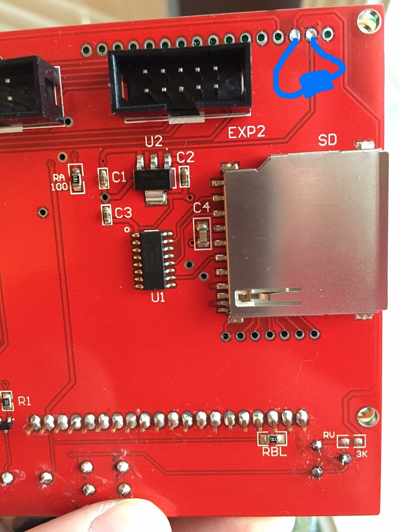
I have checked how the trimpot and my additional resistor are connected to the 20x1 pin row which is also present on your board.
I tried to draw it on top of your photo:
This is just how the resistors are connected on my board - no idea whether this also works for your board...
Could it be that your board allows setting the contrast via the software? Marlin has a corresponding parameter, but in my case it had no effect.
I tried to draw it on top of your photo:

This is just how the resistors are connected on my board - no idea whether this also works for your board...
Could it be that your board allows setting the contrast via the software? Marlin has a corresponding parameter, but in my case it had no effect.
|
Re: Controller LCD contrast issue January 13, 2015 01:28PM |
Registered: 9 years ago Posts: 10 |

|
Re: Controller LCD contrast issue January 28, 2015 01:05PM |
Registered: 12 years ago Posts: 62 |
|
Re: Controller LCD contrast issue March 15, 2015 01:33PM |
Registered: 11 years ago Posts: 5,780 |
I just received a RRD GLCD for my Smoothieboard and found the contrast very low whether powered by USB or 12V supply. After checking a bunch of threads like this one I took a closer look at the GLCD module and found that there is a tiny pot on the back side of LCD board mounted near the edge near the backlight. Unfortunately the pot is designed to be adjusted from above, but above is where the controller board is sitting. Unless you're prepared to bend all the pins that connect the two boards together to get at the adjustment you're going to need some tweezers to grip the rotor of the pot and turn it. I did just that and got the display working perfectly regardless of being powered by the USB or 12V supply.


|
Re: Controller LCD contrast issue March 21, 2015 07:36PM |
Registered: 10 years ago Posts: 903 |
Quote
the_digital_dentist
I just received a RRD GLCD for my Smoothieboard and found the contrast very low whether powered by USB or 12V supply. After checking a bunch of threads like this one I took a closer look at the GLCD module and found that there is a tiny pot on the back side of LCD board mounted near the edge near the backlight. Unfortunately the pot is designed to be adjusted from above, but above is where the controller board is sitting. Unless you're prepared to bend all the pins that connect the two boards together to get at the adjustment you're going to need some tweezers to grip the rotor of the pot and turn it. I did just that and got the display working perfectly regardless of being powered by the USB or 12V supply.
Thank you for posting this! I just finished soldering the missing LCD interface headers and 1.0A 5V regulator on my Smoothieboard, and was pulling my hair out because the display looked like black letters on a dark blue background. The vendors who copied the genuine RRD GLCD 12864 made an improvement by adding a trim pot on their interface boards to adjust the contrast, but the genuine RRD article does not have that provision except for the inaccessible one on the back of the LCD module itself.
I was thinking about drilling a small hole through the interface board to get at the trim pot until I saw your post. I was hesitant to even try it with a Dremel, because the hole would need to be very close to one of the SD card shield's ground pads. I was able to grab the top of the trim pot with thin needle-nose pliers (power off, of course!), and made a few 1/8 turn swings until it powered on looking just as sharp as your pictures above.....
|
Re: Controller LCD contrast issue May 02, 2015 05:15AM |
Registered: 9 years ago Posts: 21 |
|
Re: Controller LCD contrast issue May 02, 2015 05:49AM |
Registered: 9 years ago Posts: 21 |
|
Re: Controller LCD contrast issue June 24, 2015 11:26AM |
Registered: 9 years ago Posts: 3 |
I bought a 12864 LCD controller from banggood.I have complied with #define reprap discount full graphic smart controller. The screen powers up but displays nothing.is this same contrast issue?
Edited 1 time(s). Last edit at 06/24/2015 11:26AM by xxkrishxx.

Edited 1 time(s). Last edit at 06/24/2015 11:26AM by xxkrishxx.
|
Re: Controller LCD contrast issue June 24, 2015 02:19PM |
Registered: 8 years ago Posts: 606 |
|
Re: Controller LCD contrast issue July 05, 2015 09:45AM |
Registered: 9 years ago Posts: 3 |


|
Re: Controller LCD contrast issue August 16, 2015 12:21AM |
Registered: 10 years ago Posts: 17 |
Hi guys, to start with many thanks, so glad I found this information, otherwise would have thrown newly purchased GLCD into the bin.
Purchased from [www.ebay.com.au]
and his advice was "there is a potentiometer beside the LCD,it can adjust the contrast,please try,thanks." yes I had already tried this and makes very little difference.
I said to myself, I mean what can you expect for $13.80 it was a gamble.
I was told to send it back!, like yeah its going to cost as much as the purchase price, that realy is not an option.
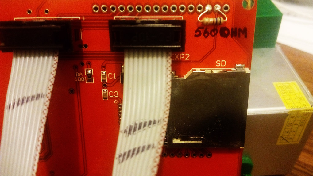
Cutting a long story short I read the info here, tried a number of resistors and settled on 560 ohms.
Now the GLCD is very usable and as good as my other $69 GLCD from rerapdiscount.
Regards - bruce
Protective film is still on the GLCD screen.
Purchased from [www.ebay.com.au]
and his advice was "there is a potentiometer beside the LCD,it can adjust the contrast,please try,thanks." yes I had already tried this and makes very little difference.
I said to myself, I mean what can you expect for $13.80 it was a gamble.
I was told to send it back!, like yeah its going to cost as much as the purchase price, that realy is not an option.
Cutting a long story short I read the info here, tried a number of resistors and settled on 560 ohms.
Now the GLCD is very usable and as good as my other $69 GLCD from rerapdiscount.
Regards - bruce
Protective film is still on the GLCD screen.
|
Re: Controller LCD contrast issue December 19, 2015 12:26PM |
Registered: 8 years ago Posts: 13 |
hey guys, i have the same issue with my LCD : it is a reprap discount smart controller, i don't know where to add the resistor
another thing, can someone explain me the three contrast pins located in top of the memory card reader ???
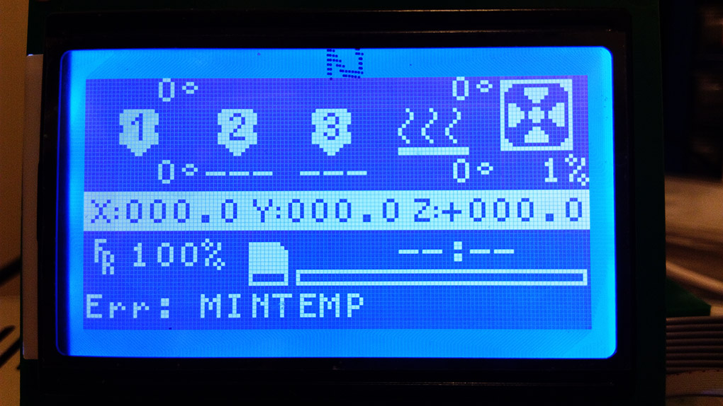
here is a picture of my LCD please tell me which resistor i should have and where to sold it and thanks
another thing, can someone explain me the three contrast pins located in top of the memory card reader ???
here is a picture of my LCD please tell me which resistor i should have and where to sold it and thanks
|
Re: Controller LCD contrast issue December 28, 2015 04:04PM |
Registered: 8 years ago Posts: 1 |
I had this same Issue with RobotLinking Full Graphic Smart Controller 12864. What I did is firs check with 470 ohm resistor as described above. It worked, but I decided to do the job as it should be - I unsold goldpin bar, then put there connector instead of soldering. Then experimentally set proper resistance with of the hidden pot. It worked VERY well :-) so thanks for advice !!!!
I had idea to drill hole id plate above but after unsoldering I measured, and calculated that it would be directly on the path on second side of plate. Uffff, it was real hazard ;-), So - DO NOT DRILL HOLE!!!
On the picture you can see pot, gold pins and gold pin connector. Remember that plate is both side so be careful with unsoldering, not to damage connection between sides.
Best Regards
glov
I had idea to drill hole id plate above but after unsoldering I measured, and calculated that it would be directly on the path on second side of plate. Uffff, it was real hazard ;-), So - DO NOT DRILL HOLE!!!

On the picture you can see pot, gold pins and gold pin connector. Remember that plate is both side so be careful with unsoldering, not to damage connection between sides.
Best Regards
glov
|
Re: Controller LCD contrast issue January 09, 2016 08:01PM |
Registered: 8 years ago Posts: 2 |
xxkirshxx
I have the same banggood display. Was your display totally white before your fix?
I have
A cross post to my detailed description of my issue.
[community.robo3d.com]
I'm still stuck. I'm not sure if my controller is bad or not.
Thanks
I have the same banggood display. Was your display totally white before your fix?
I have
A cross post to my detailed description of my issue.
[community.robo3d.com]
I'm still stuck. I'm not sure if my controller is bad or not.
Thanks
|
Re: Controller LCD contrast issue January 31, 2016 12:05PM |
Registered: 8 years ago Posts: 1 |
|
Re: Controller LCD contrast issue February 09, 2016 02:46PM |
Registered: 8 years ago Posts: 3 |
|
Re: Controller LCD contrast issue February 23, 2016 03:33AM |
Registered: 9 years ago Posts: 32 |
|
Re: Controller LCD contrast issue May 01, 2016 11:22AM |
Registered: 7 years ago Posts: 5 |
I tried 220 ohm, 330 ohm, 440 ohm and 560 ohm. 440 ohm worked for me. Mine brand is bigtree-tech.


Sorry, only registered users may post in this forum.