Pololu -> Is this schema working?
Posted by mhensen
|
Pololu -> Is this schema working? May 14, 2010 10:07AM |
Registered: 14 years ago Posts: 80 |
Just to shoot out in the open..
I am about to restart my RepRap/RepStrap adventures. Just starting from scratch!!
looking at this schema at http://www.reprap.org/wiki/Pololu_Electronics I thinks this is way much cheaper then the orginal makerbot style electronics.
The only question I have is "Will this work?? Or is this working anywhere in a reprap environment!"
I like the easy of the schema as I don't have any experience with SMD based PCB's. Even I can read it :-)
one other question suposed the schema is a correct working schema..
I asume that any stepper driver could be used here? as long as the I can get 1-2A per coil and can do up to 1/8 steps on 12V? Is this a correct assupmtion?
Perhaps some pros/cons of this circuit?
Thanks in advance and with kind regards,
Michael
Edited 2 time(s). Last edit at 05/14/2010 10:11AM by mhensen.
|
Re: Pololu -> Is this schema working? May 16, 2010 10:24PM |
Registered: 14 years ago Posts: 800 |
i like the pololu drivers my self, so far they have worked great for me. and i like them allot for my steppers.
though my driver setup is a littel differnet than the one in the wiki i do like the idea of just being able to pull out a dead driver. and putting a new one in its place.
[mike-mack.blogspot.com]
though my driver setup is a littel differnet than the one in the wiki i do like the idea of just being able to pull out a dead driver. and putting a new one in its place.
[mike-mack.blogspot.com]
|
Re: Pololu -> Is this schema working? June 03, 2010 12:23AM |
Admin Registered: 16 years ago Posts: 476 |
Pololu Electronics Thoughts:
Pros:
+ Lower cost
+ Easily replaced when one dies
+ Under active development within core team and elsewhere
Cons:
- Are a less official experimental alternative
- Cooling may be an issue (small chip, hard to heatsink well)
- Used with an Arduino Mega, currently need forked firmware
I'm just starting to attempt a Mega + Pololu approach myself, BTW, probably Johnny's Arduino_Mega_Pololu_Shield variant.
Jonathan
|
Re: Pololu -> Is this schema working? June 03, 2010 12:49AM |
Registered: 14 years ago Posts: 800 |
the one thing that, the arduino pololu shield needs is a better shield layout, and so far i have not found one that will work for what i would consider a no compromise shield i am using the arduino mega shield from arduino, and i could not get it to work in the layout i wanted, i always seemed to be off by one hole.
layout this one is close, i may or may not try it in my next revision [www.sparkfun.com]
it is more than long enough to have them all in one nice straight line but i would like to have them all in a square more than a line. but there are still a few more things for me to get done first.
and yes cooling is an issue, so far mine have not gotten very warm in my testing but thats only testing, so take that with a grain of salt.
i do like my shield but i do think i will end up making my next one on perf board unless i can find a shield that will work better for this layout, the shield is my preferred way to go though,
the other reason i like this idea, is that i can stack the shields so that if i need to use more space i can just add another shield in the middle for the stuff that dose not get has hot, and it makes for a nice and compact design i think.
i do need to make some sort of diagram of my design so that others can see it, i am bad for just working with what i can picture in my head.and working it out has i go.
[mike-mack.blogspot.com]
|
Re: Pololu -> Is this schema working? June 03, 2010 01:25AM |
Admin Registered: 16 years ago Posts: 476 |
dissidence: It's now relatively straightforward to design, and then either make yourself, or ask BatchPCB or similar places to manufacture, a PCB (or even a few PCBs), rather than using a protoboard-style shield for your work. So you do not have to be constrained by available prototyping shield layouts.
And yes, please do document your work, (preferably on the reprap.org wiki), so that others can understand it, and quite possibly use and improve on it too As you probably know, available free tools used for circuit design and board layout include Kicad, Geda and (free as in beer, not open source) Eagle.
Jonathan
And yes, please do document your work, (preferably on the reprap.org wiki), so that others can understand it, and quite possibly use and improve on it too
As you probably know, available free tools used for circuit design and board layout include Kicad, Geda and (free as in beer, not open source) Eagle.Jonathan
|
Re: Pololu -> Is this schema working? June 03, 2010 10:28AM |
Registered: 14 years ago Posts: 800 |
on that note i am looking at doing an order for the pcb design on the wiki page that is there, i may modify it a little but when i get the design posted i would like to see if any one would like to order some. any one who is interested send me a pm
[mike-mack.blogspot.com]
[mike-mack.blogspot.com]
|
Re: Pololu -> Is this schema working? June 03, 2010 05:05PM |
Admin Registered: 16 years ago Posts: 476 |
"The pcb design"?
As in Adrian's PCBs? Or Rapatan's shield? Or Johnny R's shield?
There is no shortage of PCB designs for Mega + Pololu electronics
Jonathan
As in Adrian's PCBs? Or Rapatan's shield? Or Johnny R's shield?
There is no shortage of PCB designs for Mega + Pololu electronics
Jonathan
|
Re: Pololu -> Is this schema working? June 03, 2010 08:32PM |
Registered: 14 years ago Posts: 800 |
it will be a take between my current one and johnny R's one, within a week i will have the designs posted, i hope.
[mike-mack.blogspot.com]
[mike-mack.blogspot.com]
|
Re: Pololu -> Is this schema working? June 04, 2010 12:34AM |
Registered: 14 years ago Posts: 800 |
if you want to see the start of my idea , look at the post on my blog from today june 3rd
[mike-mack.blogspot.com]
[mike-mack.blogspot.com]
|
Re: Pololu -> Is this schema working? June 04, 2010 08:30AM |
Registered: 15 years ago Posts: 186 |
Some eagle files and (yet another) arduino mega shield design here (using 10-pin IDCs for standard stepper driver boards)
[renoirsrants.blogspot.com]
:-)
---
Reprapping blog and other rants: [renoirsrants.blogspot.com]
My Reprap: [sites.google.com]
[renoirsrants.blogspot.com]
:-)
---
Reprapping blog and other rants: [renoirsrants.blogspot.com]
My Reprap: [sites.google.com]
|
Re: Pololu -> Is this schema working? June 13, 2010 12:17PM |
Registered: 14 years ago Posts: 800 |
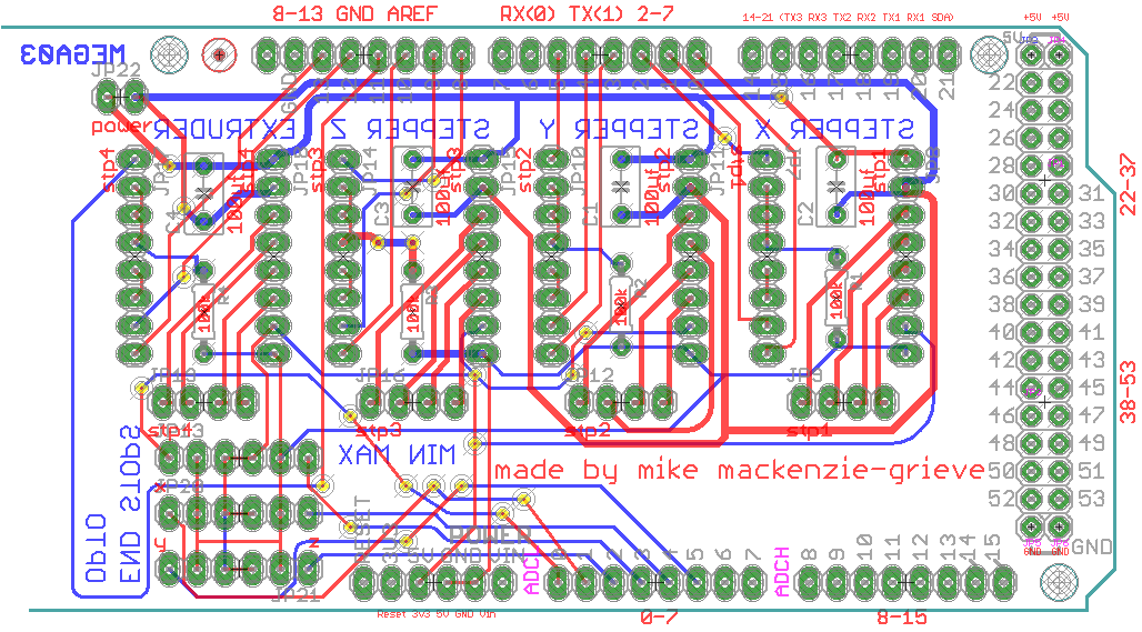
i tried to post some gerber files on thingiverse but i am not sure if they are any good but here is a pic of what i have done so far
here is the link for thingiverse mackenzie shield
i only have the free version of eagle so i hope it worked out well enough for people to work with it. and for me to finish my project with out having to buy eagle
edit
oh ya i am trying to make a wiki page but thats not going over too well, i am trying to figure out how to start a new page, i can edit them but not create then yet.
Edited 1 time(s). Last edit at 06/13/2010 12:19PM by dissidence.
[mike-mack.blogspot.com]
|
Re: Pololu -> Is this schema working? June 13, 2010 01:36PM |
Registered: 14 years ago Posts: 689 |
> i am trying to figure out how to start a new page
Just write the name of the page in the wiki url, even if it doesn't exist you get the option to edit it, and thus you create a new page.
Example: http://reprap.org/wiki/This_Is_The_Name_Of_My_New_Wiki_Page
Looking forward to more arduino and pololu stuff!
Just write the name of the page in the wiki url, even if it doesn't exist you get the option to edit it, and thus you create a new page.
Example: http://reprap.org/wiki/This_Is_The_Name_Of_My_New_Wiki_Page
Looking forward to more arduino and pololu stuff!
|
Re: Pololu -> Is this schema working? June 13, 2010 04:16PM |
Admin Registered: 17 years ago Posts: 1,791 |
Just write the name of the page in the wiki url, even if it doesn't exist you get the option to edit it, and thus you create a new page.
Example:
[reprap.org]
Yup. And use the source from [reprap.org] or any other wiki page if it seems helpful.
-Sebastien, RepRap.org library gnome.
Remember, you're all RepRap developers (once you've joined the super-secret developer mailing list), and the wiki, RepRap.org, [reprap.org] is for everyone and everything!
|
Re: Pololu -> Is this schema working? August 05, 2010 11:14PM |
Registered: 13 years ago Posts: 25 |
I'm just starting to look at making a reprap and the Pololu/ Arduino Mega electronics is interesting. Mostly interesting because I already have the Arduino Mega board. I'm looking at making the Adrian version.
The only thing that concerns me is the communication of this electronic setup to the software. I can not seem to find any documentation on this aspect of the Pololu set-up. Out of all of the abilities needed in building a reprap, programming is my most lacking area. So, if I will need to do extensive programming to make this setup work then I may have to go with the MakerBot boards.
Are there any pages documenting the communication with the software, or examples of what some people are using with this setup?
|
Re: Pololu -> Is this schema working? August 05, 2010 11:45PM |
Registered: 14 years ago Posts: 800 |
there are 2 or 3 different firmwares for the mega and i think they all use the out puts that the pololu boards need for there inputs. so in that regard, all you should need to changed is your pins for your outputs on the mega. if i remember right
[mike-mack.blogspot.com]
[mike-mack.blogspot.com]
|
Re: Pololu -> Is this schema working? August 06, 2010 04:53AM |
Registered: 16 years ago Posts: 1,094 |
both the official reprap boards and the pololu electronics accept ttl/5v step/dir signalling as do many other stepper driver chips and boards. just choose your mega-compatible firmware and check the pin allocations. Depending on your choice of firmware, you may even be able to use the enable pins to turn off the motors when they're not needed.
I'm told that my firmware should work on a mega with a little porting, maybe someone's even doing it for me
-----------------------------------------------
Wooden Mendel
Teacup Firmware
I'm told that my firmware should work on a mega with a little porting, maybe someone's even doing it for me
-----------------------------------------------
Wooden Mendel
Teacup Firmware
|
Re: Pololu -> Is this schema working? August 28, 2010 05:25PM |
Registered: 13 years ago Posts: 25 |
So, I have my electronics just about done. In a few days I will need to start testing everything.
dissidence and Triffid_Hunter, I've been looking all day for the firmware for the Arduino Mega but I cannot seem to find any specifics to which is the correct one. In some forums posts fiveD is noted, but from what I can tell fiveD is included in the normal reprap firmware. So will the regular firmware work?
I've also found this just a second ago, for the Hydra firmware. This actually has the most info I've found regarding the Mega. Anyone know if Hydra is a working firmware?
Is there another resource I'm completely missing?
|
Re: Pololu -> Is this schema working? August 28, 2010 08:37PM |
Registered: 14 years ago Posts: 800 |
you know the sad part is that i still do not have a working repstrap, i am getting there, but i am trying to learn all that i can and have had to come up with a few things on my own has well.
i was asking pretty much just that on my blog not that long ago. and i was told about Joaz firmware from github
[github.com] i am hoping to see the official one support the mega soon, but from all i know you just have to modify your input and output pins to match your hardware.
[mike-mack.blogspot.com]
|
Re: Pololu -> Is this schema working? August 29, 2010 05:13AM |
Registered: 16 years ago Posts: 467 |
Hi
[reprap.svn.sourceforge.net]
I believe this firmware is working. You need to check the pin numbers, set the correct steps and set the motherboard type.
I have a Mendel nearly complete with Pololu drives. The X Y & Z work fine with this firmware but I have not completed my extruder so I have not tested that. But Adrian did post a while back that his Pololu driven system was working. Look in the main blog
Regards
Ian
|
Re: Pololu -> Is this schema working? September 04, 2010 09:19PM |
Registered: 13 years ago Posts: 25 |
emt or anyone else working on the pololu electronics,
So I've been trying to get the Mega/pololu electronics working. I've set the motherboard to 3 (mega) and changed most of the pins. The pins I cannot figure out are for the MIN_PIN and MAX_PIN for the XYZ steppers. I figure one pin is from the opto endstop but I'm not sure for the other. Should they be set the same?
Also, I'm still in the process of searching through the forums and wiki pages, but how do I set the correct steps for the stepper motors?
-Steven
|
Re: Pololu -> Is this schema working? September 04, 2010 09:55PM |
Registered: 14 years ago Posts: 800 |
if i remember they are set to half step on a 1.8 deg/step motor, most of mine are0.9deg/step so i am just doing full stepping untill i get it working and then i will try switching to half stepping.
[mike-mack.blogspot.com]
[mike-mack.blogspot.com]
|
Re: Pololu -> Is this schema working? September 10, 2010 01:14PM |
Registered: 13 years ago Posts: 25 |
Still having problems... time for process of elimination. I would be very grateful if any one can help me here. I have gotten the Pololu/ Mega set up and it does not seem to be working right. I will list everything I've done so far and hopefully someone will catch what I'm doing wrong here.
1. I tried installing the reprap distro on a PC with Windows 7 and had problems because my drivers were not installing. Then I uninstalled Windows and installed Ubuntu. All of my driver/ port issues went away with Ubuntu. After installing the Reprap distro the program would run but I would get this in the terminal:
2. I ordered the Arduino Mega 1280 and decided to make the Pololu setup design done by Adrian. I printed and etched the boards and soldered all of the components in and attached it to the Arduino Mega. I took a bit of chance here because these boards are not tested. The materials needed to make I already had so I figured what the hell.

3. I downloaded the firmware and edited the pins in pins.h to match the appropriate pins on the board. I also switched the motherboard to 3 in the Configuration file. I ran Verify/Compile and came back with no problems so I uploaded the firmware to the Arduino board. With the 4 stepper motors and the three endstops connected I powered up the board (5v from the Arduino board and 12v from a power source).
Instantly one of the motors started vibrating as if were trying to move in both directions at once. After starting the Reprap software I tried using the controls on the XYZ tab to nudge the motors. Some would nudge .1 mm twice and then start vibrating like the other motor. If I pressed "Home All" they would move quickly in one direction and then stop vibrating (except the one that was initially vibrating). So, I figured I pressed my luck and should not have gone with the untested Adrian design.
I did test the steppers to make sure I had them wired correctly. One matching pair of wires goes to 1A and 2A, the other pair going to 1B and 2B. I think this is right according to some info I found on wiki pages, but could be wrong.
4. I started looking around to possibly buy the normal electronics. They are out of stock on Makerbot so I started looking elsewhere. While looking around on Ultimachine.com I found an Arduino/Pololu shield they are sellfing. I figured this was a better bet as it had been tested and shown to be working so I ordered one. Got the shield in ,soldered all of the components and again hooked up the 4 steppers and 3 endstops.

I changed the pin numbers again in the pin.h file according to the wiki page for the Ultimachine shield.greatful
One thing I am unsure of is the last line of code talking about using the analog input. If this is something that needs to be changed elseware, I'm not sure how to. So, after compiling the firmware I uploaded it to the board and powered everything up. With the new shield I got the same response of one or two motors vibrating and getting weird responses from trying to nudge the motors. So, no difference with this shield and the Adrian design.
5. Some of the possible problems that I am about to test in the next day.
-I may have fried the Pololu boards with the Adrian designed boards, so I need to test them and the endstops.
-The firmware needs further changes to make the Arduino/Pololu setup work that I am missing. I've searched and cannot seem to find anything posted.
If anyone has any ideas please send them my way. If it has to do with the firmware specifics would be best as my programming skills are low. Thanks to anyone in advance.
1. I tried installing the reprap distro on a PC with Windows 7 and had problems because my drivers were not installing. Then I uninstalled Windows and installed Ubuntu. All of my driver/ port issues went away with Ubuntu. After installing the Reprap distro the program would run but I would get this in the terminal:
Experimental:  JNI_OnLoad called.

Stable Library
=========================================
Native lib Version = RXTX-2.1-7
Java lib Version   = RXTX-2.1-7
RXTX Warning:  Removing stale lock file. /var/lock/LCK..ttyUSB0
Java 3D WARNING : reported GLX version = 1.2
    GLX version 1.3 or higher is required
    The reported version number may be incorrect.  There is a known
    ATI driver bug in glXQueryVersion that incorrectly reports the GLX
    version as 1.2 when it really is 1.3, so Java 3D will attempt to
    run anyway.
I searched the Reprap forums and Ubuntu forums and found no answers there. I was not even sure if it is a problem so I moved on.2. I ordered the Arduino Mega 1280 and decided to make the Pololu setup design done by Adrian. I printed and etched the boards and soldered all of the components in and attached it to the Arduino Mega. I took a bit of chance here because these boards are not tested. The materials needed to make I already had so I figured what the hell.
3. I downloaded the firmware and edited the pins in pins.h to match the appropriate pins on the board. I also switched the motherboard to 3 in the Configuration file. I ran Verify/Compile and came back with no problems so I uploaded the firmware to the Arduino board. With the 4 stepper motors and the three endstops connected I powered up the board (5v from the Arduino board and 12v from a power source).
Instantly one of the motors started vibrating as if were trying to move in both directions at once. After starting the Reprap software I tried using the controls on the XYZ tab to nudge the motors. Some would nudge .1 mm twice and then start vibrating like the other motor. If I pressed "Home All" they would move quickly in one direction and then stop vibrating (except the one that was initially vibrating). So, I figured I pressed my luck and should not have gone with the untested Adrian design.
I did test the steppers to make sure I had them wired correctly. One matching pair of wires goes to 1A and 2A, the other pair going to 1B and 2B. I think this is right according to some info I found on wiki pages, but could be wrong.
4. I started looking around to possibly buy the normal electronics. They are out of stock on Makerbot so I started looking elsewhere. While looking around on Ultimachine.com I found an Arduino/Pololu shield they are sellfing. I figured this was a better bet as it had been tested and shown to be working so I ordered one. Got the shield in ,soldered all of the components and again hooked up the 4 steppers and 3 endstops.
I changed the pin numbers again in the pin.h file according to the wiki page for the Ultimachine shield.greatful
#define X_STEP_PIN         26
#define X_DIR_PIN          28
#define X_ENABLE_PIN       24
#define X_MIN_PIN           3
#define X_MAX_PIN           2

#define Y_STEP_PIN         38
#define Y_DIR_PIN          40
#define Y_ENABLE_PIN       36
#define Y_MIN_PIN          16
#define Y_MAX_PIN          17

#define Z_STEP_PIN         44
#define Z_DIR_PIN          46
#define Z_ENABLE_PIN       42
#define Z_MIN_PIN          18
#define Z_MAX_PIN          19

#define E_STEP_PIN         32
#define E_DIR_PIN          34
#define E_ENABLE_PIN       30

#define LED_PIN            13
#define FAN_PIN            -1
#define PS_ON_PIN          -1
#define KILL_PIN           -1

#define HEATER_0_PIN        12
#define TEMP_0_PIN          2   // MUST USE ANALOG INPUT NUMBERING NOT DIGITAL OUTPUT NUMBERING!!!!!!!!!
One thing I am unsure of is the last line of code talking about using the analog input. If this is something that needs to be changed elseware, I'm not sure how to. So, after compiling the firmware I uploaded it to the board and powered everything up. With the new shield I got the same response of one or two motors vibrating and getting weird responses from trying to nudge the motors. So, no difference with this shield and the Adrian design.
5. Some of the possible problems that I am about to test in the next day.
-I may have fried the Pololu boards with the Adrian designed boards, so I need to test them and the endstops.
-The firmware needs further changes to make the Arduino/Pololu setup work that I am missing. I've searched and cannot seem to find anything posted.
If anyone has any ideas please send them my way. If it has to do with the firmware specifics would be best as my programming skills are low. Thanks to anyone in advance.
|
Re: Pololu -> Is this schema working? September 10, 2010 07:33PM |
Admin Registered: 17 years ago Posts: 7,879 |
You have the stepper motors wired incorrectly. One coil is 1A / 1B and the other coil is 2A / 2B.
See this diagram [www.pololu.com]
[www.hydraraptor.blogspot.com]
See this diagram [www.pololu.com]
[www.hydraraptor.blogspot.com]
|
Re: Pololu -> Is this schema working? September 12, 2010 11:18AM |
Registered: 13 years ago Posts: 25 |
Nophead
Thank you for the reply. The steppers motor wires were backwards... I completely goofed that one. I changed the wires around to match the diagram but now all of the stepper motors are slowly vibrating back and forth. I did notice one of the endstops had an led on. Would this be causing the problem?
I am using a computer power supply shown here so I do not know if that would be causing problems. I have tested it and it shows a steady 12v. I'm not sure how to test how many amps it is pushing but the power supply was rated for 18amps at +12volts.
|
Re: Pololu -> Is this schema working? September 12, 2010 02:46PM |
Registered: 13 years ago Posts: 7,616 |
One Ampere per Motor is totally sufficient for getting them running. At 2 amps you already max out the stepper drivers.
Vibrating motors hint to insufficient shielding, grounding and/or loose wires. Electromagnetic noise floating around triggers the STEP or DIR pin. I'd continue with removing the endstops entirely, as they have long cables which can pick up such noise well.
Oh, and I had a case where overheating the stepper drivers resulted in vibrating motors as well. These chips shouldn't get hot enough to burn your skin when touching them. If they do, attach a small heatsink (those made for RAM in a PC) or turn down the current regulator on the stepper driver.
| Generation 7 Electronics | Teacup Firmware | RepRap DIY |
|
Re: Pololu -> Is this schema working? September 13, 2010 03:50PM |
Registered: 13 years ago Posts: 25 |
Traumflug,
Thanks! It turns out the current regulators on the stepper driver were all the way up. I turned them all the way down and the vibrating has stopped. I also ordered some of those heatsinks and will attach them just in case.
One of the endstop LEDs is staying on constant so I'm guessing there is something wrong there. I'll deal with that after I get my extruder completed and test to make sure it is working with the electronics. Thanks again.
|
Re: Pololu -> Is this schema working? September 13, 2010 03:55PM |
Registered: 14 years ago Posts: 800 |
what end stops are you using, i am using the ones from the make.rrrf.org/oes2.1 i like them allot so far.
[mike-mack.blogspot.com]
[mike-mack.blogspot.com]
|
Re: Pololu -> Is this schema working? September 13, 2010 09:53PM |
Registered: 13 years ago Posts: 25 |
Dissidence- I'm using this opto kit from Ultimachine. Two of them seem to be working fine. I may have fried one of the components on the board or I may have a short.
Actually I just starting making the extruder and have run into some other problems...
I bought the Superpack Plastruder kit from MakerGear and started making the heatcore. Well, when I got to the part where I needed to heat the ceramic I hooked up the heater wires to the Ultimachine Arduino shield shown in the previous post.
I connected the heater wires to the terminal at E0H and the + connection above it. Also I hooked up the thermistor to check the temperature. It looks like the thermistor was working because when I held it pressed between two fingers the temperature went up. The problem is that the heat core never seemed to get hot. I was only able to test it for about 5 minutes before I had to leave for a class but it seemed that it was not changing temperature to the touch.
I'm not sure if this is an electronics/ firmware problem or if I have done something wrong in making the heat core. I'll also check topics in the Extruder Group in the forums.
|
Re: Pololu -> Is this schema working? September 13, 2010 10:26PM |
Registered: 14 years ago Posts: 1,092 |
|
Re: Pololu -> Is this schema working? September 14, 2010 02:38PM |
Registered: 13 years ago Posts: 25 |
I am getting some resistance through the heatcore. Not quite the 6ohms but I am getting 4.8ohms which should be enough to get some heat.
It looks like the shield is not supplying any power to the EOH and power connections. Currently I have one element wire connected to EOH terminal and the other to the + terminal right above it. I checked and am getting no power to it with the "Switch heater On" button switched on or off in the reprap client/software. I'm not sure if this is a burned up mosfet/ bad connection or something wrong in the firmware. I'm not sure how to check if the mosfet is working or not.
Actually I just found that I am getting the 12v through the + terminal. Truthly I'm unsure how the mosfet works but I'm guessing it is supposed to turn on and off the ground (-) connection to the heater element through the EOH terminal?
Amputee Parade - My Art and Reprap blog

Sorry, only registered users may post in this forum.