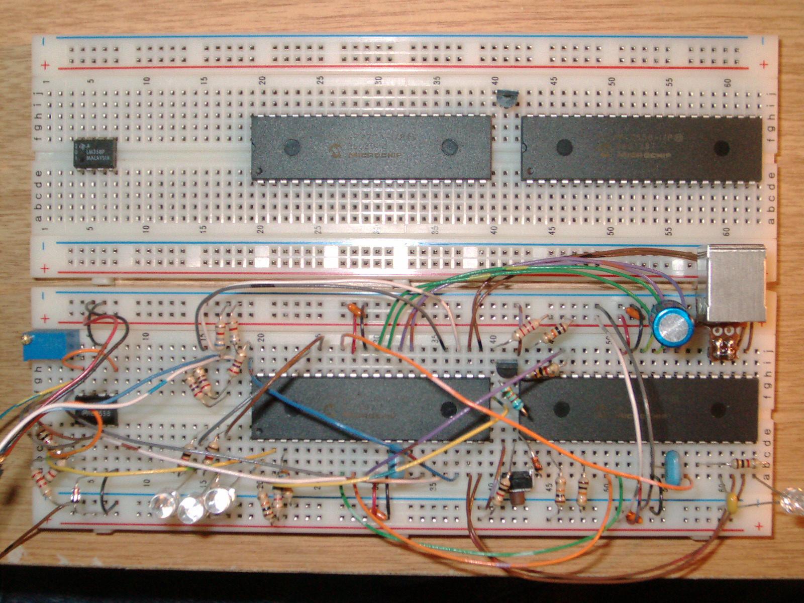
Attached are the files for building an ICD2, I'll hunt up the schematic and programming files later and post or link. The two red hashed lines in the parts picture don't belong. Just the power wires so not a real issue, did this in paint and saved before I noticed, not a real issue so not worth generating a new picture.
Get two breadboards to dedicate and sample the PICs. Build two at once, it's not really much longer than just building one since you're just plugging parts, shouldn't take an hour or two. Took me 6 or 8 on the first one, having to follow the schematic and figure where to put things for a decent arrangement and get it working, second one for the build pictures flew by even with stopping and taking pictures.
Does need an 15V to 20V or so supply, not a big deal since you tend to need one for working on the target with a regular programmer anyway. I could put in a charge pump, since the HV is only there to enter programming mode, programming is really done with the 5V on newer PICs. But I have an old laptop 18V supply with long leads I use, so it's never bothered me enough to make the pump.
And don't think a breadboard is a drawback. This is reasonably tidy and BB is only $3 or $5. About as cheap and fast to build one or two of as a PC board. It makes more sense to buy an extra BB or two and dedicate it, in fact $50 to buy a bunch of breadboards just for the 'one of' items not worth making a board for is a very good investment if you haven't done it already. It is one $50 you won't be kicking yourself for later, and when you run out and need more you'll realize how good that $50 has been.