Software motor control and back EMF as position feedback
Posted by rebecca.palmer
|
Software motor control and back EMF as position feedback November 02, 2010 08:35PM |
Registered: 13 years ago Posts: 91 |
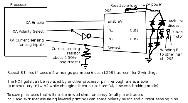
By software control, I mean replacing the Polulus with plain H-bridges (e.g. L298s), and having the main processor read the current from the sense resistors and switch each winding as required. This allows the current measurements to be used in more sophisticated ways than simply setting the current to match a given step position; in particular, as the generated back EMF and hence current depend on position,
L*dI_1/dt=V_applied1-R*I_1-k*v*cos(x)
L*dI_2/dt=V_applied2-R*I_2-k*v*sin(x)
m*dv/dt=-m*mu_friction*sign(v)+k*I_1*cos(x)+k*I_2*sin(x)
dx/dt=v (v=velocity, x=position with the cos and sin having a period of 4 full steps, 1 and 2 are the two windings)
it should be possible to obtain feedback on the motor's actual position (avoiding missed steps). This isn't as mathematically simple as the similar brushless DC control scheme using a third undriven winding for the measurement, and I haven't worked out the details yet, but I believe it can be made to work.
Software motor control has been done before, but it isn't clear whether this used such feedback or only emulated a standard driver, and his firmware does not appear to have been released.
The timescales below suggest this can be done on an ATmega644PA as long as it prints in flat layers (not moving Z and E at the same time, as they need to share some of their pins) and stops printing before trying to do anything else, but it will be a tight fit in both speed and pins, and since this will be a major firmware rewrite anyway I am open to the idea of using a different processor, as long as doing so doesn't add much cost and doesn't require the builder to solder tiny SMT pads. The STM32VL Discovery looks technically good, but with possible licence issues, while the LPC-P1343 has only 8 analog inputs so requires some of the same compromises as an ATmega.
Any comments before I move on to more detailed design?
Advantages:
Feedback avoids missed steps (without the extra hardware required by optical feedback) -> faster printing and/or lower power (cheaper?) motors
Cheaper (by maybe $20 compared to 4 Polulus with the same main processor, though I haven't done a full costing yet)
Could detect unusually high (jammed) or low (drive broken/out of filament) mechanical resistance and stop the machine (though I don't know if these are likely/damaging enough to be worth it)
Disadvantages:
A software bug could overload the motors (easily prevented with fuses)
Uses more processor pins (6-8 per motor instead of 2)-needs design compromises to fit on an ATmega644PA
More components (more work to assemble; is there an alternative to the L298 with the diodes built in? the L293D is not suitable as it has no provision for current sense resistors and a low maximum current)
Processor intensive-will probably need to stop printing to do anything else (eg. talking to the host)
Time scales (using the mendel-parts motor (2.3mH, 1.68A max, 30Ncm pull-out) on 12V and 8 steps/mm, the default speed of 3000mm/min and a rough guess of 1kg carriage weight)
2.5ms 1 step (current/voltage repeats every 4 steps = 10ms)
0.4ms Electrical time constant (0 to max rated current at full voltage, inductance limited)
0.7ms Mechanical time constant (0 to default speed at full torque)
ATmega644PA
0.16ms 8 reduced resolution A/D conversions (one per input, 7 bit accurate, can do calculations at the same time; full resolution takes 4 times longer)
0.005ms 100 CPU cycles (order of magnitude of the calculation size needed)
Processor pins (a=analog input)
Naive Optimized
8 8 Winding on/off (don't use the ATmega hardware PWM as it is much too slow, just turn them on and off in software)
8a 6a Current sensing (Z and Extruder(s) can share both this and polarity select if we don't move both at once)
16 6 Winding polarity select (since we don't need the braking function, we can use external NOT gates to do this with one pin per winding)
2 2 Heaters (extruder + bed)
2a 2a Thermistors
3-7 2 Endstops+manual stop button (All except Zmin ORed onto one pin, home one axis at a time, tripping one when not intentionally homing is an error so stop and await user input)
4 2 Host computer (V-USB needs only 2 pins, and also avoids the cost of a USB-TTL converter; since this is processor intensive, load some G-code into RAM then disable the interface while printing)
-----
43-47(10a) 28(8a) Total (1 extruder, heated bed)
+10(3a) +4(1a) Each additional extruder
Available pins: ATmega644PA 32(8a), LPC1343 42(8a)+USB, STM32VLDISCOVERY 51(16a)+USB
|
Re: Software motor control and back EMF as position feedback November 03, 2010 04:10AM |
Admin Registered: 17 years ago Posts: 1,791 |
Any comments before I move on to more detailed design?
Only 2.
Firstly: it sounds really cool.
Secondly: you're a dev doing dev. Take it to reprap-dev?
Maybe you can somehow fold it into the UBW32 Blue Banana Electronics? (For example. )
Or perhaps not. But I'd be honored if you joined us there.
-Sebastien, RepRap.org library gnome.
Remember, you're all RepRap developers (once you've joined the super-secret developer mailing list), and the wiki, RepRap.org, [reprap.org] is for everyone and everything!
|
Re: Software motor control and back EMF as position feedback November 03, 2010 12:32PM |
Registered: 16 years ago Posts: 438 |
This is a good idea, and has the potential to drasticaly reduce the cost of the electronics. I've been thinking about this since I noticed a note in the a4983 page on the allegro site:
"The A4983 interface is an ideal fit for applications where a complex microprocessor is unavailable or is overburdened. "
We have a "complex microprocessor" and thus perhaps this chip isn't for us, as we can and should be doing these tasks in software. The implication here is that the allegro chip will be more expensive, or less effective, or have other features that make it less than ideal in a situation where you can leverage an existing microprocessor.
I haven't the EE background to actually do anything with this information, and so I'm especially tickled to see that you're doing it. I've already written a hack on Triffid's "FiveD_on_arduino" software to do gray-code stepping instead of step/direction. I'd be happy to write the hack to do this as well, if I knew what the pinouts/algorythm looked like. And I'm unemployed right now, so should have time.
I have an arduino and an STM32VLDISCOVERY board (that I haven't tried to load anything onto yet) but I should be able to do a little (tiny) bit of basic testing before forwarding code to you.
--
I'm building it with Baling Wire
|
Re: Software motor control and back EMF as position feedback November 03, 2010 07:42PM |
Registered: 13 years ago Posts: 91 |
The final design won't be an Arduino (only the Mega has enough pins and at that price there are much more powerful processors available), if it is an ATmega it will be directly on the main board as in Gen7, but initially testing one axis using whatever one already has lying around makes sense.
UBW32 Blue Banana is a conventional motherboard + stepper controllers setup; PIC32 being better than ARM at toggling pins fast is relevant information, given that my proposal will involve a lot of that, but I suspect either will be good enough and the ARM is cheaper.
Technically the STM32VLDISCOVERY seems perfect for the job (plenty of pins and speed at a very low price), but I am concerned by its restrictive license: I do not want to waste time developing something that is illegal to release.
|
Re: Software motor control and back EMF as position feedback November 08, 2010 08:41PM |
Registered: 13 years ago Posts: 1,352 |
If its just about having some sort of feedback, to avoid errors, at some extent could be done with current electronics also.
Also i think that some step errors can be considered "additive" while others are not such. What is the objective. Would that restrict the boards in some ways, would that depend on some extent on the pcb layout and, and how traces are laid at some extent, how far the motors are, maybe eventual ferite cores along the wires, transformers/stations/towers nearby, etc (time to run after and catch my brain before runs further).
Maybe something can be done to monitor home state, basically getting a pulse to each full step that was ordered to motor, regardless if it actually does microstep or w/e. As far as i know this feature is mostly unused. But as a feature would just need 1 pin on mcu (or 2 coz makes good friends with reset pin) and should be fairly easy to fit or manage in firmware.
I dont think it can be considered a closed loop "per se", i am not sure of its in-deep works, but i think that basically just copies and sends back the command driver received at translator level. I dont think it actually checks outputs and reports what is exactly going out, which can be interpreted as being slightly more usefull. It wouldnt be so fancy and not as good as a true closed loop to the motor itself, its more like "something" in the middle of the way. It probably can do as much as confirming to the motherboard that the stepper chip does, indeed, received the command and is working as wanted - if it has or not a motor attached its another thing. Would this be satisfactory at some degree? Just could be worth considering advantages / disadvantages and costs/implications.
Also about 644p it seems to bite the dirt, the next set of makerbot seems to have ft232rl on the extruder which uses 328 (i think i seen it on that board instead) so i guess it would talk that way. It makes sense: avoids situations where cartesian movement was blocked/bugged and extruder kept extruding endlessly in same spot. Cartesian movement seems to use1280 or 2560, I guess things will be compatible with new flavor of atmega that is around mendel these days. I would say better to use some of that instead of 644 just for the sake of keeping things together for the future.
Edited 2 time(s). Last edit at 11/08/2010 10:46PM by NoobMan.
|
Re: Software motor control and back EMF as position feedback November 09, 2010 04:30AM |
Registered: 13 years ago Posts: 91 |
I don't actually have a RepRap, but what I've read here about missed steps points to them being the result of exceeding the motor's physical capabilities, not the driver chip getting confused (by electrical noise or otherwise). Also, there's no "monitor home state" pin on a Polulu, and if we're going to change the design we might as well do proper closed loop: the hardware isn't that complicated (1 L298, 8 diodes, 2 current sense resistors per axis), and should actually be cheaper than the existing design.
The reason for choosing the 644p is that it has the most pins available in a through-hole package: my design is intended to allow easy DIY assembly, so small-spacing SMT components such as the 1280/2560 would have to be purchased on a carrier board, adding to the cost. If it turns out to be inadequate, ARM processors seem to be a both cheaper and higher-performance way to go, though they would involve more initial work to port the firmware.
The reason for choosing the 644p is that it has the most pins available in a through-hole package: my design is intended to allow easy DIY assembly, so small-spacing SMT components such as the 1280/2560 would have to be purchased on a carrier board, adding to the cost. If it turns out to be inadequate, ARM processors seem to be a both cheaper and higher-performance way to go, though they would involve more initial work to port the firmware.
|
Re: Software motor control and back EMF as position feedback November 09, 2010 09:52AM |
Registered: 13 years ago Posts: 1,352 |
Well you said "any comments" ... I was merely trying to make something like defining the problem, see alternate paths, judge benefits value, something like that.
Indeed home, as a chip feature, doesnt seem so widespread as reset, A4983 doesnt seem to have it like a3977 / a3979 do. The fact that not all chips have it would lower even further that "limited usefullness" of a feedback like that, would be more like a self diagnose feature as mb could report at some point "X stepper driver board not connected or not working - check connections".
About DIY and tqfp packages, let me tell you the dificulties of tqfp comes from the fact that their packages in eagle are not open for changes and these needs to be done further in image editor but other than that, its fairly easy to work with as far as diy goes, if there is a good tip iron around. More details here [www.reprap.org] I did the mb 12 with 644p in tqfp and have no issues with at all. I think to start tackle with it, it takes more courage than it takes skills. I would say that in general, difficulty of tqfp package itself for diy is rather exagerated.
Anyway dont let me turn you off or influence you too much. This is just my pov (point of view) and ofc it should not be yours also.
How would you tackle with back emf calculations on different "emulations" of microstep resolutions.
I was merely trying to make something like defining the problem, see alternate paths, judge benefits value, something like that.Indeed home, as a chip feature, doesnt seem so widespread as reset, A4983 doesnt seem to have it like a3977 / a3979 do. The fact that not all chips have it would lower even further that "limited usefullness" of a feedback like that, would be more like a self diagnose feature as mb could report at some point "X stepper driver board not connected or not working - check connections".
About DIY and tqfp packages, let me tell you the dificulties of tqfp comes from the fact that their packages in eagle are not open for changes and these needs to be done further in image editor but other than that, its fairly easy to work with as far as diy goes, if there is a good tip iron around. More details here [www.reprap.org] I did the mb 12 with 644p in tqfp and have no issues with at all. I think to start tackle with it, it takes more courage than it takes skills. I would say that in general, difficulty of tqfp package itself for diy is rather exagerated.
Anyway dont let me turn you off or influence you too much. This is just my pov (point of view) and ofc it should not be yours also.
How would you tackle with back emf calculations on different "emulations" of microstep resolutions.
|
Re: Software motor control and back EMF as position feedback November 09, 2010 08:18PM |
Registered: 13 years ago Posts: 91 |
> Well you said "any comments" ... I was merely
> trying to make something like defining the
> problem, see alternate paths, judge benefits
> value, something like that.
No offence was intended: sharing tentative ideas that may not work is good, as a group of varied expertise can better evaluate which ones are worth working on than any single member.
> How would you tackle with back emf calculations on
> different "emulations" of microstep resolutions.
I'm not sure what you mean by this, and haven't yet worked out exactly how the calculation would work, but in my proposal one microstep is naturally a fixed time (as long as it takes to loop through all motor windings, on a 644P probably about 0.1ms limited by A/D converter speed, about 1/20 step at standard speed but coarser if we achieve the aim of moving faster) rather than a fixed fraction of a whole step, since we aren't using a step/direction interface.
I was merely> trying to make something like defining the
> problem, see alternate paths, judge benefits
> value, something like that.
No offence was intended: sharing tentative ideas that may not work is good, as a group of varied expertise can better evaluate which ones are worth working on than any single member.
> How would you tackle with back emf calculations on
> different "emulations" of microstep resolutions.
I'm not sure what you mean by this, and haven't yet worked out exactly how the calculation would work, but in my proposal one microstep is naturally a fixed time (as long as it takes to loop through all motor windings, on a 644P probably about 0.1ms limited by A/D converter speed, about 1/20 step at standard speed but coarser if we achieve the aim of moving faster) rather than a fixed fraction of a whole step, since we aren't using a step/direction interface.
|
Re: Software motor control and back EMF as position feedback November 10, 2010 08:10AM |
Registered: 13 years ago Posts: 1,352 |
Check this [www.piclist.com] its unipolar only, but has no h-bridges; could that become bipolar and without h-bridges can be back emf loop closed some other way? any benefits? I dont know, just asking your opinion.
In the end, if we passed the "devil advocate" stage, i think its a great ideea. It just looks complicated to me tbh, as design goes. On the other hand i think it should be easy to test or further to be put in practice. Will be certainly looking forward to see how it will work out.
In the end, if we passed the "devil advocate" stage, i think its a great ideea. It just looks complicated to me tbh, as design goes. On the other hand i think it should be easy to test or further to be put in practice. Will be certainly looking forward to see how it will work out.
|
Re: Software motor control and back EMF as position feedback November 10, 2010 05:35PM |
Registered: 13 years ago Posts: 91 |
I already have the hardware schematic worked out (but haven't yet got around to installing any electronics design software, hence the crude drawing attached; shows one winding out of 8, power supply decoupling capacitors not shown), just not the control algorithm. We aren't trying to get rid of the H-bridges (which are necessary for bipolar motors; you can in theory make your own out of 8 transistors per motor, but an L298 chip is more convenient), just move the current monitoring and control functions to the main processor, so we can do something more sophisticated than a standard driver's "change currents when told to and hope the motor position can keep up".
|
Re: Software motor control and back EMF as position feedback November 10, 2010 07:35PM |
Registered: 13 years ago Posts: 1,352 |
If you can provide a little more than that, like a paper written schematic with components instead of logic operands and such, i can happily draw it in a few hours max with layout (even for toner transfer if needed). Packages and values can be played with after and could make it on a bigger grid to have it spaced out to tamper with later.
But i am afraid i am more like an executant than a creator so i wouldnt be able to help beyond some simple tasks. Frankly i dont fully understand most of the things i tamper with, even after i make them. But again i dont really need to - just if you have a hand drawn schematic i can just replicate it in program - its easy task.
But i am afraid i am more like an executant than a creator so i wouldnt be able to help beyond some simple tasks. Frankly i dont fully understand most of the things i tamper with, even after i make them. But again i dont really need to - just if you have a hand drawn schematic i can just replicate it in program - its easy task.
|
Re: Software motor control and back EMF as position feedback November 10, 2010 07:51PM |
Registered: 16 years ago Posts: 438 |
Does this really save money? These L298's are listed as $4.67 each. That's not THAT much different than the allegro chip at $5.11 Each chip drives one stepper. The L298 approach takes some additional external components
The L298 I quoted is listed at 4A, and is a through-hole device which some people like, and it would be much easier to heat-sink. It does take some additional external components. Your diagram also calls for eight "not" gates as well. And six microcontroller pins per axis, two analog inputs, two PWM outputs, and two digital outputs. Or four digital outputs if we want to get rid of the not gates. That's 32 or 24 pins for the standard setup.
I suppose that it would give us closed-loop control of the steppers, even if it is the same cost.
I suppose that the firmware would simple define the max interrupt rate, use a sin table and test and adjust the current on each coil each time. Doable in constant time, I'd think. What's the time constant for the current rise in the steppers? make sure your pwm timer is greater than that.
You'd also have to throw an warning and adjust the target speeds when the steppers fail to keep up. Or maybe just automatically slow the other axies to match - you'd get ideal maximum possible acceleration, that'd be cool. And an error if it just can't move, like if it's stuck on something or hitting a mechanical endstop. Doing that in constant time would be a bit more challenging.
How to determine the max interrupt rate? What percentage of the processors power is it reasonable to spend adjusting the PWM values to track the target current? OK, I'll shut up now, I think I've ceased to contribute usefully.
I still wonder if it'll really save money.
--
I'm building it with Baling Wire
|
Re: Software motor control and back EMF as position feedback November 11, 2010 03:40AM |
Registered: 13 years ago Posts: 91 |
The claim of saving money was relative to the Polulu board, not the A4983 on its own, which comes only in QFN packages (0.5mm pad spacing, and they're underneath, so no access for removing any solder bridges afterwards), and also requires external components.
For pin count and time constants, see my original post; the pins would be turned on and off in software, as the AVR's hardware PWM is far too slow (~500Hz), and it can spend all its time doing this when actually moving, and stop when it needs to get/interpret more Gcode.
For pin count and time constants, see my original post; the pins would be turned on and off in software, as the AVR's hardware PWM is far too slow (~500Hz), and it can spend all its time doing this when actually moving, and stop when it needs to get/interpret more Gcode.
|
Re: Software motor control and back EMF as position feedback November 15, 2010 12:40AM |
Registered: 16 years ago Posts: 438 |
rebecca.palmer Wrote:
-------------------------------------------------------
> The claim of saving money was relative to the
> Polulu board, not the A4983 on its own, which
> comes only in QFN packages (0.5mm pad spacing, and
> they're underneath, so no access for removing any
> solder bridges afterwards), and also requires
> external components.
Ah. So it won't be cheaper than putting the A4983 (or cousins) directly on a board, but will be cheaper than the pololu breakout board. I should have paid more attention to what you actually said, as opposed to what is actually happening.
>
> For pin count and time constants, see my original
> post; the pins would be turned on and off in
> software, as the AVR's hardware PWM is far too
> slow (~500Hz), and it can spend all its time doing
> this when actually moving, and stop when it needs
> to get/interpret more Gcode.
That approach probably won't work well. The firmware MUST be receiving and interpreting gcode while moving. Hesitation between line segments leads to blobing, as the extruder doesn't stop instantly. Many people experienced this with some of the first arduino-based electronics. Not that it would make it useless, but putting a hard upper limit on your print quality sounds like a bad idea. If you have to take time off to process g-code, you will see it in the print. And if you have to talk to the host *and* process g-code, it'll be quite noticeable. It was a big deal when that limitation was removed, and the firmware gained proper buffering of pre-calculated moves.
I don't think this'll really be workable on a 644p. An EE friend of minds is fond of saying "software is like a gas - it expands to fill all available space." I think that's correct, but it's also true that software is like a gas, you *can* cram a great deal of it into a very small space. It then becomes difficult and expensive to work with, and prone to leaks and other odd behavior.
My advice? Get a bigger bottle. I think that requires moving away from a DIP package. Also you'd then gain enough pins to dispense with the NOT gates, reducing part count and possibly allowing fancier braking or whatever.
--
I'm building it with Baling Wire
|
Re: Software motor control and back EMF as position feedback November 15, 2010 07:06AM |
Registered: 16 years ago Posts: 1,094 |
ahem, the AVR's hardware PWM can run at F_CPU/256, 62.5KHz from a 16MHz clock... I think it's just the arduino libraries that slow it down for some reason- one of many reasons I don't use them 
-----------------------------------------------
Wooden Mendel
Teacup Firmware
-----------------------------------------------
Wooden Mendel
Teacup Firmware
|
Re: Software motor control and back EMF as position feedback November 15, 2010 06:19PM |
Registered: 13 years ago Posts: 91 |
jgilmore Wrote:
-------------------------------------------------------
> Hesitation between line segments
> leads to blobing, as the extruder doesn't stop
> instantly. Many people experienced this with some
> of the first arduino-based electronics. Not that
> it would make it useless, but putting a hard upper
> limit on your print quality sounds like a bad
> idea. If you have to take time off to process
> g-code, you will see it in the print. And if you
> have to talk to the host *and* process g-code,
> it'll be quite noticeable. It was a big deal when
> that limitation was removed, and the firmware
> gained proper buffering of pre-calculated moves.
That is a potentially major problem with a "stop and think" design (though was this back when the extruder motor was still DC? a stepper can be slowed to a stop under control and held stopped, but the plastic might still ooze under its own weight).
As for getting it to interpret and move at the same time, the "move" interrupt would be the A/D conversion complete interrupt, and would probably need to be somewhere near its maximum rate of one per 416 cycles (0.02ms) to work well, compared to one per ~0.05ms for 3 axis 1/16 microstepping, and there is more calculation to do for each step; missing the odd one isn't a problem, as the feedback will realign the estimated position with the actual position, but anything as demanding as V-USB communication probably won't work.
I plan to run some simulations of the algorithm to establish what speed it requires before committing to any particular processor.
More powerful options that are still through hole:
Two processors (one to do V-USB communication + interpreting + non-time-critical controls (ie the heaters), one to run the motors)
PIC18 8 bit 64MHz, 36 I/O pins including 13 analog inputs
Propeller 32 bit 80MHz, 32 I/O, no analog inputs but external A/D converters are cheap and would free up some pins
Carrier boards: STM32 Discovery is technically near-perfect but with a license that bans us from using it, LPC 1343 (32 bit 72MHz, 42 I/O inc. 8 analog + USB ) has a grid of holes (not pins) which would make for a mess of wiring, most others are relatively expensive
Moving to TQFP64: if we are using a milling head to make the PCB, can we make a deep enough cut between pads to make running a finger down the row a reliable method of getting solder paste on the pads only, rather than a starting point that is likely to require some fiddly short removal afterwards? If that could be made to work reliably, it sounds easier than soldering 40 through-hole pins, as well as giving us a wider choice of processor.
|
Re: Software motor control and back EMF as position feedback November 16, 2010 07:18AM |
Registered: 13 years ago Posts: 1,352 |
I was checking for a force sensor to use for calibrating the height of the nozzle vs the table due to heat elongations and while looking at a few, dumb things came to my mind:
- how about a senzor to detect the 3 axis movement as feedback? like an 3 axis accelerometer or some of those cheap sensors - i doubt anything would have the resolution to detect a missed step tho so utility of it would be very limited
- scanner - there is a scanner on makerbot to scan things, i doubt it has a very good resolution either but how about more on IR or ultrasound to aquire 3d objects on same machine, that would be able to acquire some sort of "very rough" head position also
About how good the resolution of these can get, how fast or how much computing power would be needed for to constantly keep it up, beats me tho.
Just wanted to ask if there is any practicality for something like that.
|
Re: Software motor control and back EMF as position feedback November 16, 2010 08:48AM |
Registered: 14 years ago Posts: 248 |
rebecca.palmer Wrote:
> using it, LPC 1343 (32 bit 72MHz, 42 I/O inc. 8
> analog + USB ) has a grid of holes (not pins)
> which would make for a mess of wiring, most others
> are relatively expensive
This is incorrect, the holes are duplicated and you have a grid or you can fit SIL pins to the edge connectors.
The main issue you will have with the LPC1343 is it doesn't have native PWM.
|
Re: Software motor control and back EMF as position feedback November 16, 2010 03:22PM |
Registered: 16 years ago Posts: 438 |
rebecca.palmer Wrote:
-------------------------------------------------------
> As for getting it to interpret and move at the
> same time, the "move" interrupt would be the A/D
> conversion complete interrupt, and would probably
> need to be somewhere near its maximum rate of one
> per 416 cycles (0.02ms) to work well, compared to
> one per ~0.05ms for 3 axis 1/16 microstepping, and
> there is more calculation to do for each step;
> Moving to TQFP64: if we are using a milling head
> to make the PCB, can we make a deep enough cut
> between pads to make running a finger down the row
> a reliable method of getting solder paste on the
> pads only, rather than a starting point that is
> likely to require some fiddly short removal
> afterwards? If that could be made to work
> reliably, it sounds easier than soldering 40
> through-hole pins, as well as giving us a wider
> choice of processor.
This would definitely be my preferred option. It's likely to be much cheaper as well, since we aren't paying for a seperate carrier board for the micro. If the major cost savings benefit from this design is skipping the A4983 carrier boards, it make much sense to skip the micro carrier board as well.
So who has a milling setup on their mendel and can run a series of tests? If it works well it would also be desirable to make an all-smd (except for mosfets, etc?) version of the existing schematics that could be made more easily at home due to easier soldering and fewer or no holes to drill. (harder part placement though, those things are TINY)
I have a McWire-based thing which more-or-less works. And a dremel-type thingy I could mount on it. No blank boards or parts to try soldering on to them though. Also, the McWire design was originally made for milling circuit boards, and is more accurate than the mendel, so it wouldn't be a fair test.
--
I'm building it with Baling Wire
|
Re: Software motor control and back EMF as position feedback November 16, 2010 05:50PM |
Registered: 13 years ago Posts: 91 |
> - how about a senzor to detect the 3 axis movement
> as feedback? like an 3 axis accelerometer or some
> of those cheap sensors
Using separate sensing hardware would be another way to get feedback, and an optical encoder would be precise enough to detect missed steps; the advantage compared to my scheme is that it can track the actual carriage (i.e. including any mechanical imperfections) rather than the motor, the disadvantage is that it is extra hardware to pay for.
My scheme can track force as well as position, and yes this could be useful for determining whether a head is actually touching the work (eg. PCB milling, where imperfect flatness of the blank is reported to limit accuracy).
> If it works well it would also be desirable to make an all-smd (except for mosfets, etc?) version of the existing schematics
This already exists: the standard Makerbot board. I agree that if this were to become the easier method, we too should use it for nearly everything (but avoid the really tiny stuff, TQFP64 is already right at the limit of our milling methods).
I'm currently busy elsewhere, I expect to have time to start properly working on this in about 2 weeks.
|
Re: Software motor control and back EMF as position feedback November 17, 2010 01:38PM |
Registered: 13 years ago Posts: 1,352 |
I do toner transfer so cant test milling but i think tqfp should be doable in milling aswell, as usual routing bits can go as low as 0.20-0.30 mm diameter (some even less ofc but i dont think it would be our case). Imo, dip or tqfp are the same in terms of diy, both doable, any differences would be rather minor.
I would rather "think big" - i like the expression. Better to go with something that fits the specs at some good margin and is largely available. So, 4 motors and maybe have a hefty room for more e.g. future developments / customizations etc. Like Makerbot's automated build platform i think that is one dc motor but could work better with stepper feedback too, just not sure if torque would be enough, so 1, or better 2 extra h-bridges.
If processing power and speed is enough i think arduino could / should be prefered as it has the potential of making things much easier for many ppls - most of community already has under one form or another. Probably 328 or 1280/2560 since it seems these will be widespread in the future. I have pic18 blanks (f452) and pickit3 debugger and i think its quite a good product. I also like the tinyclr.com just for the can and the coolness factor of the cobra touchscreen board which is sexy . As a sidenote i think in the new Makerbot extruder 3.6 there is a FT232 making me think they moved the communication away from the 1280 so it can do only motor movement (incl extruder i guess), which to me makes perfect sense and in turn seems particularly good thing for this design also, better system with extruder for usb communication, better temp updates, etc. Also see the first comment on this link - Mr. Nophead blog: [hydraraptor.blogspot.com] one guy said something starting with L297 and tiny instead, not sure how relevant but at least something positive.
Edited 5 time(s). Last edit at 11/17/2010 02:54PM by NoobMan.
I would rather "think big" - i like the expression. Better to go with something that fits the specs at some good margin and is largely available. So, 4 motors and maybe have a hefty room for more e.g. future developments / customizations etc. Like Makerbot's automated build platform i think that is one dc motor but could work better with stepper feedback too, just not sure if torque would be enough, so 1, or better 2 extra h-bridges.
If processing power and speed is enough i think arduino could / should be prefered as it has the potential of making things much easier for many ppls - most of community already has under one form or another. Probably 328 or 1280/2560 since it seems these will be widespread in the future. I have pic18 blanks (f452) and pickit3 debugger and i think its quite a good product. I also like the tinyclr.com just for the can and the coolness factor of the cobra touchscreen board which is sexy
. As a sidenote i think in the new Makerbot extruder 3.6 there is a FT232 making me think they moved the communication away from the 1280 so it can do only motor movement (incl extruder i guess), which to me makes perfect sense and in turn seems particularly good thing for this design also, better system with extruder for usb communication, better temp updates, etc. Also see the first comment on this link - Mr. Nophead blog: [hydraraptor.blogspot.com] one guy said something starting with L297 and tiny instead, not sure how relevant but at least something positive.Edited 5 time(s). Last edit at 11/17/2010 02:54PM by NoobMan.
|
Re: Software motor control and back EMF as position feedback December 24, 2010 06:09PM |
Registered: 13 years ago Posts: 91 |
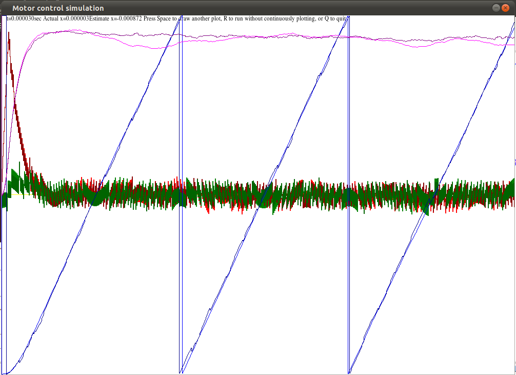
The attached plot and source is a simulation of this method accelerating from rest to 400 steps/s (blue=position, purple=velocity, red and green=current in each winding; pale=actual, dark=algorithm's estimate; only one axis is simulated).
It seems to work, but I don't know whether the noise levels I assumed are realistic.
With the parameters used here, it uses about 2 arithmetic ops/us/axis (fairly even mix of addition and multiplication, a few table lookups (for sin and cos), no division; not yet sure how many bits wide they need to be), but I haven't yet tried to optimize this.
I have dropped the idea of trying to squeeze everything into 40 pins, and now favour a 2 (or possibly even 3) processor design, to provide enough pins to avoid design compromises and enough processing power (one each for X, Y and E?).
|
Re: Software motor control and back EMF as position feedback December 27, 2010 06:16PM |
Registered: 13 years ago Posts: 91 |
Adjusting the parameters and removing some code that turned out not to be doing anything useful brought the required processor speed down to about 0.5 arithmetic ops/us/axis.
The closed loop control allows it to use only as much current as needed for the requested speed (less waste heat) and run right up to its physical maximum speed (about 400mm/s for my (guessed) parameters) without missing any steps, while a conventional driver will miss steps without warning if its limits are exceeded, and hence must err on the side of caution (more current, less speed) to avoid this.
I currently favour a 3 PIC processor design, as the 16 bit PIC24/dsPIC family are some of the most powerful processors available in DIY-friendly packaging: 40 MIPS on the PIC24H/dsPIC33, 16 MIPS and a USB OTG port (i.e. it can act as USB host, e.g. for printing from a USB stick) on the PIC24F. Both are available as through hole or as SOIC (large (1.27mm pitch) surface mount) with 28 pins. PIC24F+2xPIC18 (the latter to provide enough pins) would probably do, but I intend to go with PIC24F+dsPIC+PIC18 to have some spare processing power.
(I/O pin counts exclude MCLR/PGM/HWB to allow in-circuit programming; a=analog)
PIC18 (USB device only): 48MHz PDIP40/TQFP44 33(13a) PDIP28/SOIC28 22(10a)
PIC18K: 64MHz PDIP40/TQFP44 34(13a) PDIP28/SOIC28 23(10a)
8 bit, 1 cycle add or unsigned multiply, A/D conversion time ~12us, no pin remapping
AVR USB: 16MHz TQFP64(some can host) 47(8a), TQFP32 21(0a), plus dedicated USB pins
8 bit, 1 cycle add, 2 cycle multiply, A/D conversion time ~65us, factory installed bootloader (programmable over USB )
PIC24F (USB OTG): 16MIPS PDIP28/SOIC28 19(9a), TQFP44 33(13a)
dsPIC30: 30MIPS PDIP40/TQFP44 30(9a, or 13a 5us) PDIP28/SOIC28 20(6a)
PIC24H/dsPIC33: 40MIPS PDIP28/SOIC28 21(10a), TQFP44 35(13a)
16 bit, 1 cycle add or multiply, A/D conversion time ~1us, pin remapping
LPC1343 carrier board 72MHz 32 bit 42(8a)+USB
(ARM (all versions I know of), AVR32 and PIC32 use the smaller (0.5mm pitch) TQFP, so using them without a carrier board would be difficult)
Total pins available:
PDIP(through hole) PIC18+PIC24F+dsPIC30 82(31-34a)
PDIP PIC18+PIC24F+PIC24H/dsPIC33 73(32a)
SOIC(surface mount, 1.27mm pitch) PIC18+PIC24F+PIC24H/dsPIC33 62(29a)
SOIC 2xPIC18+PIC24F+PIC24H/dsPIC33 84(39a)
TQFP(surface mount, 0.8mm pitch) PIC18+PIC24F+PIC24H/dsPIC33 100(39a)
TQFP AVR-USB+PIC24F+PIC24H/dsPIC33 79(26a)-115(34a)+USB
Pins required:
32(8a) 4 steppers
4(2a) Heaters+thermistors
8 Inter-processor communication (UART; 12 for SPI)
5 USB (1 host, 1 device)
3 Endstops
1 Pause switch
---
53(10a)
Optional extras:
10(3a)-4(1a) Additional extruder (lower figure does not allow simultaneous use)
2(1a) Milling head (DC motor)
2a Heater current monitoring (+1a per additional extruder)
3 High limit endstops
4-7 User interface LEDs (printing, finished/ready, paused (by code M226 or hardware switch), error) or LCD display
4 SPI interface (e.g. to ENC28J60 Ethernet controller)
Approx costing (Farnell, through hole; SMT is slightly cheaper):
£3 PCB blank
£13 Processors
£9 L298s
£1 Heater MOSFETs
£3 Back EMF diodes
£3 (or free using the trace resistance) Current sense resistors
£1 Resettable fuses (to protect the motors from software bugs)
£1 Decoupling capacitors
£4 (optional) 16x2 LCD display
--
£38 (i.e. for about the price of 4 Polulus you get the motherboard as well)
|
Re: Software motor control and back EMF as position feedback December 28, 2010 02:57PM |
Registered: 16 years ago Posts: 438 |
I find it odd that you're planing a multi-processor design. All four axises would have to be controlled from within the same microprocessor to get the timing of everything correct. Unless you have a "step now" signal line somewhere, and wouldn't that defeat the purpose?
Commercially produced boards aren't that expensive, which allows you to use a small, cheap, processor with plenty of pins that still costs less than $10. There's also the ~$10 STM32VLDISCOVERY board, which is perfect for your current application (You're prototyping it, right?) Maybe design a DIY shield for that processor board, suitable for all those who want to build it themselves, and also have the schematic commercially produced as a single-board solution. (That's what the license is about on those boards anyway, they don't want somebody buying hundreds of them and using them in a commercial production product)
Requiring a carrier board for the DIY folks is a small price to pay for the vastly decreased software complexity. Or at least, that's my opinion on multiple processors. It's not worth the time & additional software complexity. Complex software takes much more time to get right.
I noticed that you didn't include any costs for connectors. Those aren't all that expensive though.
The advantages of this design go beyond "cheaper". With the more-frequent PWM updates you're getting quieter operation. You can guarantee that it'll never lose steps, due to the continuous measurement of position, which is *huge*. You have less power consumption and higher speeds. Uhm, that's all I can think of at the moment, but I'm sure there's at least a couple more. It's a superior design.
--
I'm building it with Baling Wire
|
Re: Software motor control and back EMF as position feedback December 28, 2010 06:51PM |
Registered: 13 years ago Posts: 1,352 |
I havent followed exactly everything on the list, but its naturally pretty much the same requirements with the MB2.4 and EC3.6 currently from makerbot. I would check that - its basically a arduino mega board (2560?) with a ec 328. Is there any chance that as a platform may be up to the task - maybe with some changes? If you would go for that, and if you are like within europe, i am planning to make myself a set next ~2 months and i could make you a free one for and send for postage. Would just be some extremely eugly manual DIY toner transfer job, but at least i could put there any single change you may wish to make, if you want to hack into it without limits.
If, as a platform, is not fast enough for the task, i would check the status of the guys who are trying to port to arm - [forums.reprap.org] i am under the impression there is a plan to produce those boards too.
On the general ideea, making a platform choice is pretty hard because of so many options and products out there, but its certainly a first milestone and a foundation brick layed down. Right now, gratz for this process and also happy holidays and a new year
|
Re: Software motor control and back EMF as position feedback December 29, 2010 08:27AM |
Registered: 13 years ago Posts: 91 |
The multiple processors are to get enough I/O pins and 2 USB ports (one for the host computer, and one for a memory stick, as I consider being able to print without a continuously-connected host an important feature: the host might crash, or it might not be convenient to have it next to the RepRap), hence my proposed combinations being "something fast (to do the main calculations)" (PIC24H/dsPIC)+"something with a USB OTG port" (PIC24F)+"something with a USB port and lots of pins" (PIC18). The communication between them would be along the lines of "set port A to 5Ch" "read port B", nothing requiring complicated synchronization.
This approach is cheap because it can be all DIY, not because its components are inherently cheaper: the components on a Gen6 board probably add up to slightly less than mine (their DRV8811 costs only slightly more than an L298, and they only need one processor), but the assembled board costs Eur130 (£111). However, I agree that cheapness is far from its only advantage, and that if it works as well as I hope, there is likely to be demand for a ready-made version for convenience.
The problem with an ATmega would be processing speed: I suspect its native 8 bit precision isn't enough, and simulating 16 bit in software would probably be too slow. (Atmel do also make more powerful processors, but in non DIY friendly packaging, and this is such a major firmware change that there is little advantage in keeping the same processor architecture.)
|
Re: Software motor control and back EMF as position feedback February 16, 2013 06:32AM |
Hi Rebecca
Have you made any progress on this idea? I see the last post was 2 years ago... Can you detect back EMF / motor current for single (non-continuous rotation) microsteps? I'm struggling with a problem with torque input deflecting the stepper shaft away from its unloaded position. When the load is removed, the shaft returns to its normal, unloaded position. The motor does not lose any steps and still steps the same angle under load vs no load. It just doesn't seem stiff enough to maintain the shaft at an exact (microstep) position under load. The position tolerance for stepper motors (5% usually) only seems to apply for an unloaded motor.
I would love to have some kind of electronics that would sense when there is a load on the system and automatically compensate for this by adjusting the current outputs accordingly. Optical encoders with the required resolution to do this are quite expensive.
|
Re: Software motor control and back EMF as position feedback February 18, 2013 03:21PM |
Registered: 13 years ago Posts: 91 |
Styler Wrote:
-------------------------------------------------------
> Can you detect back
> EMF / motor current for single (non-continuous
> rotation) microsteps? I'm struggling with a
> problem with torque input deflecting the stepper
> shaft away from its unloaded position
No: the feedback signal is speed*{cos,sin}(position), so at low speed it becomes undetectable and one has to drop back to the standard approach of using more current than one expects to need and hoping it's enough.
For static position sensing, you need separate sensing hardware: there are some (old) sensor designs here, here and here.
Sorry, only registered users may post in this forum.