Heatbed mosfet @30A, 12V
Posted by LarsK
|
Heatbed mosfet @30A, 12V June 18, 2016 11:15PM |
Registered: 9 years ago Posts: 346 |
Hey,
I have gotten my self a silicon-heating-pad that runs 12V, 360W ( 30A) . This is fixed, it could be argued that it would have been better to get a AC heating pad, or 24V pad..... But here we are. Also buying a ready made module is not an option.
I have come across two potential components that I think can run it, now I just want to make sure that I am not making anything stupid so I ask here for opinions.
Option (1) - IRLB8743 - [www.infineon.com]
Main advantage; Gate threshold voltage is just 2.35V and it is physically small. I just can't believe I am reading the spec sheet right. Can it really handle that much A? At gate voltage 2.35V, could I even run it directly on a Duet 3V pin if I wanted?
Option (2) - G80N60 - [www.datasheetspdf.com]
A big type IGBT, need 12V on the gate. As long as I can get it to open and close this one can eat anything.
--
Bonus question:
Originally I just wanted to use the Duet or RAMPS MOSFET, and use that to control my new and bigger MOSFET in a separate circuit, so, use my control board MOSFET like a regular transistor. But then I read I should use an optocoupler, I thought you only put optocoupler when you have different power-levels?
PS. I have the cables with correct gauge and 12V PSU to power this. So that part is under control.
|
Re: Heatbed mosfet @30A, 12V June 19, 2016 03:05AM |
Registered: 8 years ago Posts: 5,232 |
|
Re: Heatbed mosfet @30A, 12V June 19, 2016 03:07AM |
Registered: 9 years ago Posts: 346 |
|
Re: Heatbed mosfet @30A, 12V June 19, 2016 07:21AM |
Registered: 12 years ago Posts: 1,236 |
The thing is, even if the device is 99% efficient, that leaves 3W or so to dissipate in the device. The IRLB8743 has junction-to-ambient of 62 deg/W, so that would be a temperature rise of 186 deg (package in free air), clearly not feasible.
Generally, the thermal performance of these packages on their own is pretty terrible, and they are designed to be used with an external cooling solution, hence the tab and hole for a bolt. When you start pushing up the current, external cooling becomes a necessity.
Even a small heatsink and fan provides significant cooling.
What is Open Source?
What is Open Source Hardware?
Open Source in a nutshell: the Four Freedoms
CC BY-NC is not an Open Source license
|
Re: Heatbed mosfet @30A, 12V June 19, 2016 10:18AM |
Registered: 10 years ago Posts: 14,672 |
For 30A I would use a good quality SSR. Definely not a SSR-40DD. There is an SSR that has been mentioned on these forums before that would be suitable, I think the brand name starts with A. There are also some Crydom SSRS that would be suitable, but they cost more. The Power Expander from reprap.me is another possibility but I suspect that the connector and PCB traces may not be rated for 30A.
Large delta printer [miscsolutions.wordpress.com], E3D tool changer, Robotdigg SCARA printer, Crane Quad and Ormerod
Disclosure: I design Duet electronics and work on RepRapFirmware, [duet3d.com].
Large delta printer [miscsolutions.wordpress.com], E3D tool changer, Robotdigg SCARA printer, Crane Quad and Ormerod
Disclosure: I design Duet electronics and work on RepRapFirmware, [duet3d.com].
|
Re: Heatbed mosfet @30A, 12V June 19, 2016 12:01PM |
Registered: 9 years ago Posts: 346 |
Hey,
Thank you for replies so far.
@ BOBC and O_Lampe - If I opt to just use one IRLB8743 with active cooling, would that not be a potential fire-hazard seeing how these things does not have thermal shutdown? If the fan for some reason stops it can be really bad? I prefer intrinsic safe whenever possible.
|
Re: Heatbed mosfet @30A, 12V June 19, 2016 12:24PM |
Registered: 9 years ago Posts: 893 |
Quote
dc42
The Power Expander from reprap.me is another possibility but I suspect that the connector and PCB traces may not be rated for 30A.
The PCB traces are quite wide - but I've only used mine for around 12A, so I can't be 100% certain of the maximum current-carrying capacity. As for the connectors - I didn't fit them, soldering my wires directly to the pads instead, as recommended by reprap.me.
|
Re: Heatbed mosfet @30A, 12V June 19, 2016 01:34PM |
Registered: 8 years ago Posts: 5,232 |
Quote
LarsK
Hey,
Thank you for replies so far.
@ BOBC and O_Lampe - If I opt to just use one IRLB8743 with active cooling, would that not be a potential fire-hazard seeing how these things does not have thermal shutdown? If the fan for some reason stops it can be really bad? I prefer intrinsic safe whenever possible.
There are fans with a third wire for PC cooling. They send a speed signal, which could be used for safety. AFAIK such code isn't implemented in 3d printer-universe yet.
Passive cooling or a second fan for redundancy is also an option.
I:m cooling my ramps1.4 with 2pcs. 40x10 fans, while one would be good enough.
Edited 1 time(s). Last edit at 06/19/2016 01:41PM by o_lampe.
|
Re: Heatbed mosfet @30A, 12V June 19, 2016 04:10PM |
Registered: 8 years ago Posts: 260 |
|
Re: Heatbed mosfet @30A, 12V June 19, 2016 04:30PM |
Registered: 9 years ago Posts: 346 |
Quote
amigob
just put 3 of them parallel with the drain on a large peace of the copper on the PCB and done. No active cooling needed.
Also you don't have to worry to much about the 10A per MOS fet pin.
Thanks for the input. It confirms what I was thinking, so I think that will be it. I remembered I saw a heat-sink in an old PSU that I opened some time back. I opened it backup and extracted the sink for this purpose, looks like this:
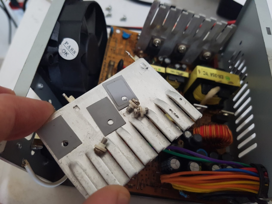
It will be great for my 3 MOSFET I think. Then if I can figure it out, I will do 2 layer PCB with drain and source on a side each.
I am sure it is turning toward overkill now, but if it is another fan in my setup or this bulky setup then I prefer the bulky passive setup.
One question remains - Should I make a separate circuit via an optocoupler for driving the gate or is it OK just to pull it directly off a RAMPS / DUET pin?
When I say RAMPS / DUET it is because I am wiring all this up on a RAMPS to test it and then when I am done cleaning up the setup and short-circuits out of the way I will change to a DUET 0.6.
|
Re: Heatbed mosfet @30A, 12V June 20, 2016 04:25AM |
Registered: 8 years ago Posts: 260 |
There is one thing you really should take care of and that is that if the the wire gets cut or the control board has no power, the fet's need to switch off.
Another thing you selected a mos fet with a 4.5V on voltage, realist that you only have 3.3V at the output ( on resistance is very high with 3.3 volt, high power dissipation ).
You can try without opto coupler but I think you really need a voltage shifter. And a optocoupler can do that also. But in the simplest form a optocoupler is directly also a inverter.
So you need to add an extra transistor to make the switch non inverted because of the safety statement above.
For a project I couldn't find an cheap opto coupler that could be driven directly by the output of the 32 bit atmel.
With power electronics it is not always easy.
P3steel DXL, with Due/RADDS/Raps128 dual Wade's extruder
|
Re: Heatbed mosfet @30A, 12V June 20, 2016 11:38AM |
Registered: 9 years ago Posts: 346 |
Quote
amigob
There is one thing you really should take care of and that is that if the the wire gets cut or the control board has no power, the fet's need to switch off.
Another thing you selected a mos fet with a 4.5V on voltage, realist that you only have 3.3V at the output ( on resistance is very high with 3.3 volt, high power dissipation ).
You can try without opto coupler but I think you really need a voltage shifter. And a optocoupler can do that also. But in the simplest form a optocoupler is directly also a inverter.
So you need to add an extra transistor to make the switch non inverted because of the safety statement above.
For a project I couldn't find an cheap opto coupler that could be driven directly by the output of the 32 bit atmel.
With power electronics it is not always easy.
Thank you for the reply.
I have a couple of options available.
(1) BSS138 - "N-Channel Logic Level Enhancement Mode Field Effect Transistor" - I think this is the right one to use.
According to the IRBL8743 datasheet the MOSFET is in the linear region at ~20A independent if I run it at Vgs= 5V or 12V.
What are the pros / cons to running the logic gate at VCC (12V) and use that on the MOSFET gate as compared to putting a linear regulator on and pulling it down to 5V on the gate?
(2) MAX3373 - A level translator designed for I2C and other data package. I got them to control 5V displays with 3.3V. I am pretty sure this one wont work because it can't supply enough current (?)
(3) 4n35 optocoupler. I am not so much in favor of this. The main advantage of the optocoupler is that I can make it an isolated circuit. Meaning the heat-bed can run on one PSU and steppers / control board on a different one... But I now understand (thank you) that this will require an even more complicated circuit so not sure I am much in favor of this still.
Edited 2 time(s). Last edit at 06/20/2016 11:40AM by LarsK.
|
Re: Heatbed mosfet @30A, 12V June 20, 2016 12:55PM |
Registered: 10 years ago Posts: 14,672 |
The comment about 3.3V does not apply to you, because you have said that you will use RAMPS or Duet, both of which provide 5V gate drive. However, it's not advisable to take too much notice of the characteristic curves published on the datasheet, because they show typical curves at the typical gate threshold voltage, but the gate threshold voltage can vary quite widely between devices. The safe values to use are the maximum Rds(on) values, which are quoted at a particular gate to source voltage, usually 4.5V for the mosfets we are talking about.
One of the problems with using fets to switch 30A is that the resistance of the wire between common ground that the mosfet source terminals will reduce the amount of gate drive provided. For example, if that resistance is 0.03 ohm, then at 30A you will have 0.9V voltage drop across it; so the mosfet source terminals will be at +0.9V and the gate to source voltage will be reduced by that 0.9V. Using an optocoupler or an SSR (which has an optocoupler or a digital isolator built in) avoids that problem.
Large delta printer [miscsolutions.wordpress.com], E3D tool changer, Robotdigg SCARA printer, Crane Quad and Ormerod
Disclosure: I design Duet electronics and work on RepRapFirmware, [duet3d.com].
|
Re: Heatbed mosfet @30A, 12V June 20, 2016 03:00PM |
Registered: 9 years ago Posts: 346 |
Quote
dc42
The comment about 3.3V does not apply to you, because you have said that you will use RAMPS or Duet, both of which provide 5V gate drive. However, it's not advisable to take too much notice of the characteristic curves published on the datasheet, because they show typical curves at the typical gate threshold voltage, but the gate threshold voltage can vary quite widely between devices. The safe values to use are the maximum Rds(on) values, which are quoted at a particular gate to source voltage, usually 4.5V for the mosfets we are talking about.
One of the problems with using fets to switch 30A is that the resistance of the wire between common ground that the mosfet source terminals will reduce the amount of gate drive provided. For example, if that resistance is 0.03 ohm, then at 30A you will have 0.9V voltage drop across it; so the mosfet source terminals will be at +0.9V and the gate to source voltage will be reduced by that 0.9V. Using an optocoupler or an SSR (which has an optocoupler or a digital isolator built in) avoids that problem.
Hmm, I understand the problem. If it is 0.9V then at 5V drive it can put us below the 4.5V - But even with V(gs) 4V we are still in the linear region (@ 30A) where they are all pretty much the same voltage drop so it will still work I guess.
|
Re: Heatbed mosfet @30A, 12V June 25, 2016 04:57PM |
Registered: 9 years ago Posts: 346 |
Hey,
So it is up and running with the RAMPS. In the end I also put resistors (and LED) on the board so that I can take any 5V and drive it with that.
The heatsink still gets hot but I can keep my finger on it without big discomfort so it is within. I used a 3x connector with 15A on each channel and split the power cable leads between them. Then 2 of those in each end. Only used single sided PCB as I had to adjust my ambitions to my skills
Right now it is a big mess with all the cables and the PCB looks really bad, anyways, here are some photos:
One thing for next revision is getting the plus terminal on the PCB also. As it is now I have to have this loop back and fourth to the PSU
So it is up and running with the RAMPS. In the end I also put resistors (and LED) on the board so that I can take any 5V and drive it with that.
The heatsink still gets hot but I can keep my finger on it without big discomfort so it is within. I used a 3x connector with 15A on each channel and split the power cable leads between them. Then 2 of those in each end. Only used single sided PCB as I had to adjust my ambitions to my skills
Right now it is a big mess with all the cables and the PCB looks really bad, anyways, here are some photos:


One thing for next revision is getting the plus terminal on the PCB also. As it is now I have to have this loop back and fourth to the PSU
|
Re: Heatbed mosfet @30A, 12V June 27, 2016 03:17PM |
Registered: 8 years ago Posts: 33 |
|
Re: Heatbed mosfet @30A, 12V June 28, 2016 05:09PM |
Registered: 9 years ago Posts: 346 |
Hey, sure, as below:
and
I have to go to Picasaweb to link photos, can't get it to reliably work from Google Photos... Strange...
The PCB has feets and all but the power cables are so stiff that I can't turn it and put it on the table but I don't feel like investing the time to fix it when I am moving to Duet anyways.
Edited 1 time(s). Last edit at 06/28/2016 05:10PM by LarsK.

and

I have to go to Picasaweb to link photos, can't get it to reliably work from Google Photos... Strange...
The PCB has feets and all but the power cables are so stiff that I can't turn it and put it on the table but I don't feel like investing the time to fix it when I am moving to Duet anyways.
Edited 1 time(s). Last edit at 06/28/2016 05:10PM by LarsK.
|
Re: Heatbed mosfet @30A, 12V June 28, 2016 08:01PM |
Registered: 7 years ago Posts: 49 |
Which gauge of wire did you use? Did you make the PCB yourself?
I'm guessing it should be possible to directly connect mosfets to the cable, but how would you do that to cable which is significantly thicker than the mosfet's leads? I have heat sinks and an old atx psu I can salvage, but I can't make PCBs, so I have to directly connect the cables.
I'm guessing it should be possible to directly connect mosfets to the cable, but how would you do that to cable which is significantly thicker than the mosfet's leads? I have heat sinks and an old atx psu I can salvage, but I can't make PCBs, so I have to directly connect the cables.
|
Re: Heatbed mosfet @30A, 12V June 28, 2016 11:08PM |
Registered: 9 years ago Posts: 346 |
Hey,
About the PCB;
Yes, it is home made. I have a laser and wanted to use the awesome method of VDX. But my skills in building stuff failed me and my laser refuses to be sharp enough to burn the paint proper. It only makes marks. So I went with the low tech way...
The entire process is this:
1) I use Eagle CAD to make the layout
2) Spray a blank PCB board with a black paint. The cool way is to get a laser to burn away the paint... The less cool, and what I did here;
Use a screwdriver or similar to take away the paint where you do NOT want the copper to be
3) Put the PCB that you etched into a mixture of HCL and H2O2;
Now, the below picture is things I actually DID make with my laser, the PCB you saw I am actually using for this MOSFET thing is with a screwdriver....
Next remove the paint with Acetone:
And there you have it. PCB ready. Now you need to drill the required holes and solder parts on.
Making PCB's is time consuming but not high tech. The chemicals can be purchased on the internet these days. See before mentioned thread of VDX.
About gauge of wires:
I actually do not know what I am using. I got some leftover cable from a temporary connection for a big aircon unit. The copper is Ø3 as shown below (AWG 9 maybe). I think you can look at how your heat-bed arrived (if it has soldered leads) and make something like it. Also you can put cable in parallel so if you have 3 x thick cable that is also OK. Like, take 3x gauge 13 will have the same capacity.
Disclaimer (as always ) - I am no electronic expert. I am learning many of these things as I go and most of this is something I am doing for the first time. The above is to the best of my knowledge / understanding, but that doesn't it any way mean it is the best way.
Edited 1 time(s). Last edit at 06/28/2016 11:10PM by LarsK.
About the PCB;
Yes, it is home made. I have a laser and wanted to use the awesome method of VDX. But my skills in building stuff failed me and my laser refuses to be sharp enough to burn the paint proper. It only makes marks. So I went with the low tech way...
The entire process is this:
1) I use Eagle CAD to make the layout

2) Spray a blank PCB board with a black paint. The cool way is to get a laser to burn away the paint... The less cool, and what I did here;
Use a screwdriver or similar to take away the paint where you do NOT want the copper to be

3) Put the PCB that you etched into a mixture of HCL and H2O2;

Now, the below picture is things I actually DID make with my laser, the PCB you saw I am actually using for this MOSFET thing is with a screwdriver....

Next remove the paint with Acetone:

And there you have it. PCB ready. Now you need to drill the required holes and solder parts on.
Making PCB's is time consuming but not high tech. The chemicals can be purchased on the internet these days. See before mentioned thread of VDX.
About gauge of wires:
I actually do not know what I am using. I got some leftover cable from a temporary connection for a big aircon unit. The copper is Ø3 as shown below (AWG 9 maybe). I think you can look at how your heat-bed arrived (if it has soldered leads) and make something like it. Also you can put cable in parallel so if you have 3 x thick cable that is also OK. Like, take 3x gauge 13 will have the same capacity.

Disclaimer (as always
) - I am no electronic expert. I am learning many of these things as I go and most of this is something I am doing for the first time. The above is to the best of my knowledge / understanding, but that doesn't it any way mean it is the best way.Edited 1 time(s). Last edit at 06/28/2016 11:10PM by LarsK.
|
Re: Heatbed mosfet @30A, 12V June 28, 2016 11:48PM |
Registered: 7 years ago Posts: 49 |
Judging by an online table, that looks like 9 awg wire, which should be plenty for 30a 12v. I'm the same in terms of electronics knowledge, so I'm still trying to figure out the maths for how to calculate wire current capacity. I Think 9 awg should be plenty for transferring 30a if not much more. I have some 10 & 15 awg house wiring I'm trying to figure out how to connect to a mosfet, and I'd rather not risk setting up a bonfire in my workshop.
What I'm thinking of doing is to crimp the cable from the board's negative to a eyehole crimp and bolt it to the mosfet's flange, and then cutting off the drain pin before soldering the other cable to the source pin. Gate should only need some normal hookup wire.
How are you attaching your cables to your board? My board came with cables attached, but honestly they seem way too thin to pass anywhere close to 30a.
300x300mm PCB Heat bed's cable joints
Here is a closeup picture of my board's solder pads, and the cables that came with it. As you can see, the joint isn't exactly superb, and the cable looks like standard 20 awg hookup wire. It seems like there are also attachment points for an LED and resistor, but I'll worry about that later. I wrote to the store, but they said that this would work and that I should give it a try at least.
Should I even bother trying to connect the board to a power supply or will that result in instant spontaneous combustion? Or should I try replacing the cables with 2.5mm 10awg and seeing how that works? How would I even connect it to such small solder pads?
|
Re: Heatbed mosfet @30A, 12V June 29, 2016 12:30AM |
Registered: 9 years ago Posts: 346 |
Whoa that is some crazy solder. I wouldn't trust that heatbed without a lot of testing. You can connect it directly to your PSU to let it heat up, but be careful, if these solders are as bad as they look you can have so much heat at the interface that it hurts the heatbed.
I am not sure how to fix it. I would say you need the wire strands to come flat down to the pad to avoid thermal expansion problems and poor bonding.
About gauge, I have come to understand the following:
[en.wikipedia.org]
If you look at the Ampacity in the table. It says that with AWG 10 you will see 60C on the copper surface when running 30A.
In that it also says that my stranded wire is 10% less actual copper wire compared to solid.
that is some crazy solder. I wouldn't trust that heatbed without a lot of testing. You can connect it directly to your PSU to let it heat up, but be careful, if these solders are as bad as they look you can have so much heat at the interface that it hurts the heatbed. I am not sure how to fix it. I would say you need the wire strands to come flat down to the pad to avoid thermal expansion problems and poor bonding.
About gauge, I have come to understand the following:
[en.wikipedia.org]
If you look at the Ampacity in the table. It says that with AWG 10 you will see 60C on the copper surface when running 30A.
In that it also says that my stranded wire is 10% less actual copper wire compared to solid.
|
Re: Heatbed mosfet @30A, 12V June 29, 2016 12:49AM |
Registered: 7 years ago Posts: 49 |
so going by that chart, if I use 3 IRLB8743 mosfets in parallel with 10 awg multi-stranded wire, mount everything on heat sinks and cool the cabinet, it should be enough to prevent anything getting significantly warm? For attaching it to the heat bed, what about if I scrape off some of the silk screen covering the large copper traces at the bottom and solder the 10 awg cables to those?
|
Re: Heatbed mosfet @30A, 12V June 29, 2016 03:31AM |
Admin Registered: 16 years ago Posts: 13,886 |
... you'll need a pretty big thermal cooler and additive measures to remove the heat, or it will get hot.
I'm using a pair of IRF1404 in parallel for currents of up to 15 Amps and it gets warm with 3Amps continuous and will go over 50degC with 10 Amps continuous, if not clamped to a big thermal mass (mostly the aluminium profiles of my Z-axis on the CNC-mill).
Here are images of my first prototype and the last 'comercial' driver, I'm using for the 3.5W@445nm- and the 9W@975nm-diodes (the left module is actually equipped with a blue 3.5W-diode).
In the second image you can see the thick copper wires I'm using for the "high-current"-traces - I'm soldering them too along the thick traces on the etched PCB's to reduce the danger of burning/melting them
Viktor
--------
Aufruf zum Projekt "Müll-freie Meere" - [reprap.org] -- Deutsche Facebook-Gruppe - [www.facebook.com]
Call for the project "garbage-free seas" - [reprap.org]
I'm using a pair of IRF1404 in parallel for currents of up to 15 Amps and it gets warm with 3Amps continuous and will go over 50degC with 10 Amps continuous, if not clamped to a big thermal mass (mostly the aluminium profiles of my Z-axis on the CNC-mill).
Here are images of my first prototype and the last 'comercial' driver, I'm using for the 3.5W@445nm- and the 9W@975nm-diodes (the left module is actually equipped with a blue 3.5W-diode).
In the second image you can see the thick copper wires I'm using for the "high-current"-traces - I'm soldering them too along the thick traces on the etched PCB's to reduce the danger of burning/melting them


Viktor
--------
Aufruf zum Projekt "Müll-freie Meere" - [reprap.org] -- Deutsche Facebook-Gruppe - [www.facebook.com]
Call for the project "garbage-free seas" - [reprap.org]
|
Re: Heatbed mosfet @30A, 12V June 29, 2016 08:48AM |
Registered: 9 years ago Posts: 346 |
Quote
A_Designs
so going by that chart, if I use 3 IRLB8743 mosfets in parallel with 10 awg multi-stranded wire, mount everything on heat sinks and cool the cabinet, it should be enough to prevent anything getting significantly warm? For attaching it to the heat bed, what about if I scrape off some of the silk screen covering the large copper traces at the bottom and solder the 10 awg cables to those?
Sounds solid to me.
|
Re: Heatbed mosfet @30A, 12V June 29, 2016 10:54AM |
Registered: 7 years ago Posts: 49 |
Hmm, so for your prototype, you've used a plain eye hole board, and used approx. 14 awg copper wire for connecting them?
So should I do the same and mount my mosfets onto a eye hole pcb and use thick copper wire traces, or just affix the heat sinks to a metal cabinet and use the wire to directly connect to the mosfets? Both setups would have the same heat sinks & active cooling, I just want to know if its worth using a PCB when I can directly crimp and solder the cables to the mosfet's flange & leads.
So should I do the same and mount my mosfets onto a eye hole pcb and use thick copper wire traces, or just affix the heat sinks to a metal cabinet and use the wire to directly connect to the mosfets? Both setups would have the same heat sinks & active cooling, I just want to know if its worth using a PCB when I can directly crimp and solder the cables to the mosfet's flange & leads.
|
Re: Heatbed mosfet @30A, 12V June 29, 2016 11:17AM |
Admin Registered: 16 years ago Posts: 13,886 |
... I have some pretty old comercial drivers, where the wires were directly crimped to the legs of the transistors, so this was not uncommon some 30+ years ago
Sometimes I'm crimping wires to legs too, but aditionally solder them, to get better surface contact and to prevent eventual corrosion.
As you can see, the legs of the shunt resistors (the thick green ones) are thinner than the copper wire and in another high current driver I'm using them for up to 10 Amps per shunt and MOSFET ... the copper wire is maybe a bit thicker than needed, but I have some ten 100m-rolls of them to use, so found them handy.
When connecting to the coolers, I'm using isolating sheets and sleeves, as the flange is connected to the driving voltage (12V or 24V with my drivers) - with the prototype this was no problem, but I've isolated them in the 'comercial' driver to avoid connecting the +12V to the housing ...
Viktor
--------
Aufruf zum Projekt "Müll-freie Meere" - [reprap.org] -- Deutsche Facebook-Gruppe - [www.facebook.com]
Call for the project "garbage-free seas" - [reprap.org]
|
Re: Heatbed mosfet @30A, 12V June 29, 2016 01:17PM |
Registered: 7 years ago Posts: 49 |
Do you have any pictures of the old commercial driver mosfets? I suppose if the crimping method worked 30+ years ago, it still should 
I'm thinking that twisting the 14awg wire then inserting the mosfet's lead in the center should provide the maximum possible contact area, before flowing solder into the joint, although sometimes electrical physics can be counter-intuitive.
I'm thinking that twisting the 14awg wire then inserting the mosfet's lead in the center should provide the maximum possible contact area, before flowing solder into the joint, although sometimes electrical physics can be counter-intuitive.
|
Re: Heatbed mosfet @30A, 12V June 29, 2016 01:42PM |
Admin Registered: 16 years ago Posts: 13,886 |
... solder has much lower conductivity than copper or silver and can 'travel' when heated and/or forced -- so better press/crimp the 'hard' conductive parts together and then inflate the gaps with solder.
I'll try to find some of the 'crimped' drivers ...
Viktor
--------
Aufruf zum Projekt "Müll-freie Meere" - [reprap.org] -- Deutsche Facebook-Gruppe - [www.facebook.com]
Call for the project "garbage-free seas" - [reprap.org]
I'll try to find some of the 'crimped' drivers ...
Viktor
--------
Aufruf zum Projekt "Müll-freie Meere" - [reprap.org] -- Deutsche Facebook-Gruppe - [www.facebook.com]
Call for the project "garbage-free seas" - [reprap.org]
|
Re: Heatbed mosfet @30A, 12V June 29, 2016 02:09PM |
Admin Registered: 16 years ago Posts: 13,886 |
... didn't find the crimped driver (could be, I have it salvaged for parts), but here some other samples of "vintage connecting" high current parts:
Viktor
--------
Aufruf zum Projekt "Müll-freie Meere" - [reprap.org] -- Deutsche Facebook-Gruppe - [www.facebook.com]
Call for the project "garbage-free seas" - [reprap.org]


Viktor
--------
Aufruf zum Projekt "Müll-freie Meere" - [reprap.org] -- Deutsche Facebook-Gruppe - [www.facebook.com]
Call for the project "garbage-free seas" - [reprap.org]
|
Re: Heatbed mosfet @30A, 12V July 12, 2016 08:09AM |
Registered: 7 years ago Posts: 5 |
A couple of observations. At a 5V gate voltage, you are dissipating roughly 3.5W in each MOSFET. If you use a totem-pole circuit to drive them (2 transistors) and maybe a third one to invert the input, so you have 12 V on the gates, you will dissipate 2.7W in each MOSFET. That will help a bit with the heat, but I would add a 12-20V zener diode and a resistor between the gate of the MOSFETs and ground just to be safe. these MOSFETs are very sensitive on their gates, so a zener diode and gate will protect them from spikes that might be picked up by the wiring. Also make sure you have a fuse in the supply line. Normally if you have gate damage on these MOSFETs, they tend to fail into a conductive state. I would also put a thermal fuse or switch on the hotbed (dont know why it is not a standard on hotbeds).

Sorry, only registered users may post in this forum.