MKS Gen 1.4 circuit and pinouts
Posted by marcwolf1960
|
MKS Gen 1.4 circuit and pinouts March 06, 2017 07:44PM |
Registered: 9 years ago Posts: 2 |
Hi All
I have a MKS Gen 1.4 board and I'd like to do some 'hacking' - adding additional functions using spare pins as well as adding wireless to it.
I can see there are several empty holes on the board that look like they could be used for this. However I need a circuit to be sure. Does anyone have one as well as what the pins on the board are.
Many thanks
Dave
|
Re: MKS Gen 1.4 circuit and pinouts March 07, 2017 06:09AM |
Admin Registered: 13 years ago Posts: 6,998 |
many LOL's
MKS don’t do open source, they just take from it.
There is no full documentation.
There is only the one pager, which lists most things
MKS don’t do open source, they just take from it.
There is no full documentation.
There is only the one pager, which lists most things

|
Re: MKS Gen 1.4 circuit and pinouts July 30, 2018 10:37PM |
Registered: 7 years ago Posts: 7 |
@Dust thanks for the picture.
What confuses me is:
1. Why are those bottom ports called servos, if they are numbered D4, D5 etc. Can they used as PWM?
2. If there is nothing plugged in to a port, does that mean the pin is available for us to use? (Unsure if it might be connected elsewhere on the board)
3 I notice in Marlin some external things are setup ready for us to define a pin. Eg Layer fan, extruder fan , controller fan. How do we know what pin number to use? - Tried looking at pins.h, doesn't help me much unless I can read and understand all the code.
4. Unsure what is supported easily (fans, cameras etc) Is there a tutorial somewhere?
5. Are we limited to the #defines in Marlin or can we implement our own extensions to use the available ports.
Edited 1 time(s). Last edit at 07/30/2018 10:46PM by SimonSolar2C.
|
Re: MKS Gen 1.4 circuit and pinouts July 31, 2018 12:15AM |
Admin Registered: 13 years ago Posts: 6,998 |
1) the plugs are designed so a servo can just plug in, since they have the gnd and +5v in the standard place for a servo.
You can use the Data pin for anything you like* (as long as the you also change the firmware)
*as long as the pin has the hardware to do what you want. EG the pin has to have PWM hardware to do PWM
See [www.arduino.cc]
All the pins on the servo ports can to PWM as that is how servos are controlled
2) depends on the pin. eg the pins at the top right table are for the step, direction and enable of each stepper. If you using the on board stepper module you cant use these.
3) you have to read the code... for your board... pins_MKS_BASE.h and pins_RAMPS.h
4) additional fans are easy, depends what you mean by a camera. just a trigger, is easy a full camera is impossible.
5) you have the full source code you can implement what you want. (if you know what your doing)
|
Re: MKS Gen 1.4 circuit and pinouts January 03, 2019 06:43AM |
Registered: 10 years ago Posts: 153 |
Quote
Dust
3) you have to read the code... for your board... pins_MKS_BASE.h and pins_RAMPS.h
As Simon said (!) "Tried looking at pins.h, doesn't help me much" looking at pins_RAMPS.h doesn't help me much either when trying to identify let's say the pin numbers for the 5V pins left of the servo pins.
I want to connect a layer cooling fan (5v) to a 5v pin with enough current. The MKS Base Gen 1.4 has a 5v pin left of the servo pins. I need to define those pins for the layer fan in configuration.h.
I also cannot trace the paths from the MCU to those 5v pins from the PCB images of that board.
All I could do is to list all the pin numbers in pins_RAMPS.h with their respective funtion and guess that the ones left at the end are those 5v pins.
Do I oversee something?
Blog: Capotexl
Filament Factory - How to build your own cheap filament extruder
Frankenstein Laser Engraver
Make the world a better place
|
Re: MKS Gen 1.4 circuit and pinouts January 03, 2019 08:02PM |
Admin Registered: 13 years ago Posts: 6,998 |
Quote
ianmcmill
I want to connect a layer cooling fan (5v) to a 5v pin with enough current. The MKS Base Gen 1.4 has a 5v pin left of the servo pins. I need to define those pins for the layer fan in configuration.h.
I also cannot trace the paths from the MCU to those 5v pins from the PCB images of that board.
5v pins are directly connected to 5v power, not related to IO pins in any way shape or form, They are just always on power pins.
You can't just magically redefine them and turn them into software controlled IO pins.
No IO pin can directly provide the current you want.
You need to do one of the following.
A) Pick an free IO pin, connect that to a mosfet, provide the mosfet with 5v to be turned on and off.
You then define the correct fan pin to use the IO pin you selected
 You can use any currently unused mosfet, just connect you fan +v to external 5v and the fan -v to the mosfet -ve pin. Also Connect external 5v gnd to gnd on the controller.
 The on board 5v rail will not have sufficient current to power this beast of a fan.
(2 amp for a fan, the machine will probably blow itself around the room)
Edited 3 time(s). Last edit at 01/03/2019 08:10PM by Dust.
|
Re: MKS Gen 1.4 circuit and pinouts January 07, 2019 01:52PM |
Registered: 10 years ago Posts: 153 |
Quote
Dust
Quote
ianmcmill
I want to connect a layer cooling fan (5v) to a 5v pin with enough current. The MKS Base Gen 1.4 has a 5v pin left of the servo pins. I need to define those pins for the layer fan in configuration.h.
I also cannot trace the paths from the MCU to those 5v pins from the PCB images of that board.
5v pins are directly connected to 5v power, not related to IO pins in any way shape or form, They are just always on power pins.
You can't just magically redefine them and turn them into software controlled IO pins.
No IO pin can directly provide the current you want.
You need to do one of the following.
A) Pick an free IO pin, connect that to a mosfet, provide the mosfet with 5v to be turned on and off.
You then define the correct fan pin to use the IO pin you selected
The on board 5v rail will not have sufficient current to power this beast of a fan.
(2 amp for a fan, the machine will probably blow itself around the room)
I feared that answer. I hoped, however, that I might have overlooked something.
MOSFET air soldering is it then.
Thanks

Blog: Capotexl
Filament Factory - How to build your own cheap filament extruder
Frankenstein Laser Engraver
Make the world a better place
|
Re: MKS Gen 1.4 circuit and pinouts January 22, 2019 06:38PM |
Registered: 10 years ago Posts: 134 |
Seeing the MKS ??? 1.4 in this thread, I got this confused with the MKS Sbase (which I have the 1.3 version of, and also has a 1.4 version apparently)
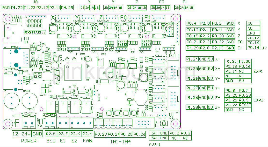
Needing to use some free TTL pins (for a relay board and a MOSFET to turn on a laser) I put together a list of pins for the MKS Sbase.
I put together a spreadsheet (LibreOffice calc but should open in Excel) which maps the CPU pins used in Smoothieware config to the silkscreened connectors on the board. Since there is a set of duplicates I've called the power output connectors on the bottom edge BED-PWM, E1-PWM, E2-PWM and FAN-PWM.
I used this as a starting point: [smoothieware.org]
I had some initial confusion as there are different versions of the "green diagram pinout" and some of them are for earlier versions of the board which don't have J7 and J8.
I also don't know what are the functions of TRST, TCK and TMS on J2.
Support from MKS is nonexistent but their goal seems to have been to provide a claim of equivalent functionality to the Smoothieboard. I thought it would be useful to compare the pinouts.
Edited 2 time(s). Last edit at 01/22/2019 06:52PM by papergeek.
Sorry, only registered users may post in this forum.