New (4) Stepper Driver Board!
Posted by Andrew Diehl
|
New (4) Stepper Driver Board! March 28, 2011 10:29PM |
Registered: 13 years ago Posts: 581 |
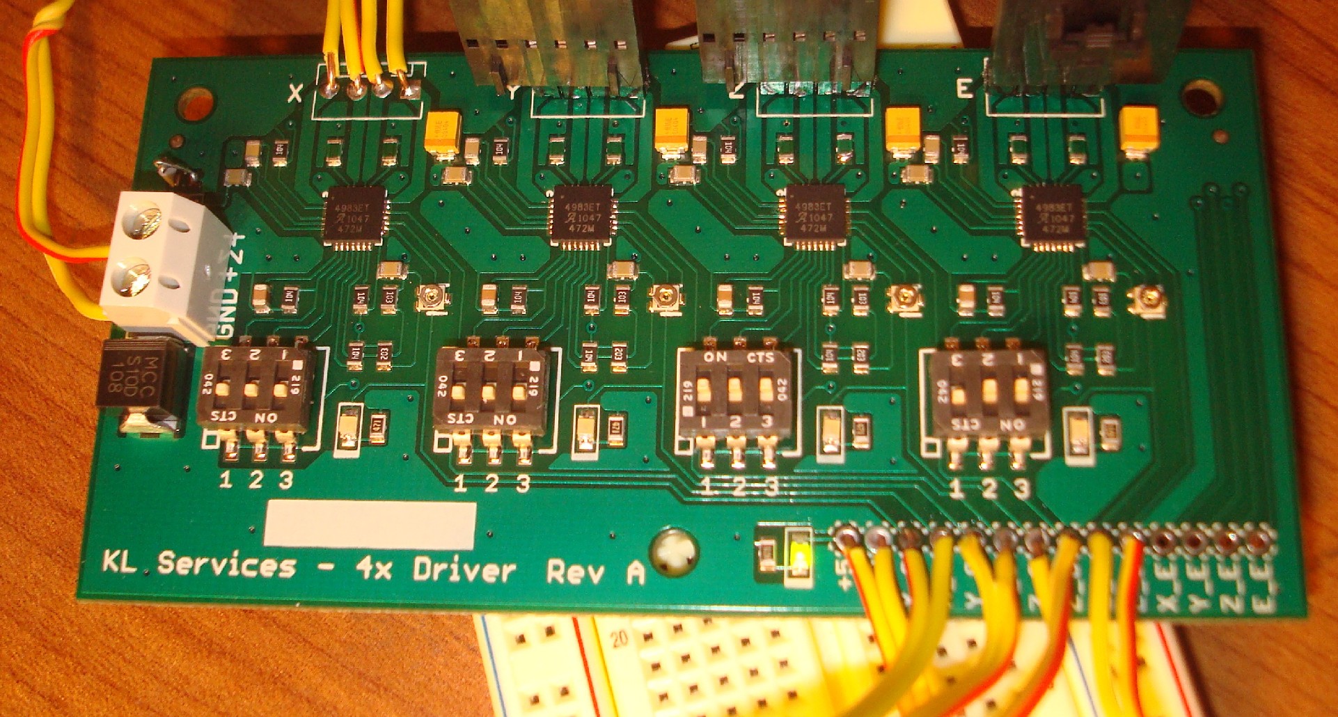
I just finished assembling the first prototype. Works perfectly so far, no magic smoke!
It's a remake of the A4983 chips used on the pololu stepper driver board. The difference is there are built in microstepping selectors, reverse polarity protection, and indicator led's for logic power, driver power, and step inputs. All the parts are 0803 or larger for reliability. Lots of space was left around the chips so a single long heat sink could be mounted over all the driver chips if desired, and there is generous copper on the bottom of the board for further heat dissipation. Boards are professionally assembled with a pick and place machine and conveyor reflow oven.
With any luck I'll have this board integrated with an atmega 328, some mosfets, and thermocouple/thermistor inputs next month.
Would anyone (preferably in the US) be interested in helping me test a few of these out on working repraps? It will work with any board that outputs step and direction signals, +5v, and +8 to 24V for driver power.
I'm planning on doing some more testing to be reasonably assured they will work perfectly, before building up the rest of the boards I have.
Once the design is finished i'll do a wiki entry including the eagle files to keep sebastian happy
Comments welcome!
Edited 1 time(s). Last edit at 03/29/2011 12:49AM by Andrew Diehl.
|
Re: New (4) Stepper Driver Board! March 29, 2011 04:26AM |
Registered: 13 years ago Posts: 818 |
Hi Andrew
That's a nice layout, good job.
It maybe nice to have a local 5v regulator option so you don't need to route it from the main-board (if it's being used separately).
Add some holes along the row of A4983's so as you say a sprung heat-spreader can be fixed across all of them.
Think about making your motor connections 0.156" it looks like they are 0.1" at the moment?
If you have space around the dill switches put the stepping settings on the silk-screen
Also add + and - to the silk screen for the pot (motor current) people always turn them the wrong way.
Do you have a PTC resettable fuse?
Think about routing the REF pin to a spare connector - I always fancied reading this voltage on the main-board so you can report the current being set by the pot on each channel.
Maybe you could also set the current limit for each channel in software if you have a few spare pins to control a simple resistor ladder. - I'll have to try that.
Other than that, think about making a 5 channel layout (E2) or just make a single channel version for future expansion.
I did a few similar little expansion channels with dill switches etc. in the RAMPS style -
It's a shame your in the US, I would really like to help you test it - if I can help in any way, just let me know.
Good luck with it.
Rich.
[richrap.blogspot.com]
That's a nice layout, good job.
It maybe nice to have a local 5v regulator option so you don't need to route it from the main-board (if it's being used separately).
Add some holes along the row of A4983's so as you say a sprung heat-spreader can be fixed across all of them.
Think about making your motor connections 0.156" it looks like they are 0.1" at the moment?
If you have space around the dill switches put the stepping settings on the silk-screen
Also add + and - to the silk screen for the pot (motor current) people always turn them the wrong way.
Do you have a PTC resettable fuse?
Think about routing the REF pin to a spare connector - I always fancied reading this voltage on the main-board so you can report the current being set by the pot on each channel.
Maybe you could also set the current limit for each channel in software if you have a few spare pins to control a simple resistor ladder. - I'll have to try that.
Other than that, think about making a 5 channel layout (E2)
or just make a single channel version for future expansion.I did a few similar little expansion channels with dill switches etc. in the RAMPS style -

It's a shame your in the US, I would really like to help you test it - if I can help in any way, just let me know.
Good luck with it.
Rich.
[richrap.blogspot.com]
|
Re: New (4) Stepper Driver Board! March 29, 2011 04:36AM |
Admin Registered: 17 years ago Posts: 1,791 |
Once the design is finished i'll do a wiki entry including the eagle files to keep sebastien happy
Don't forget to wave it at reprap-dev at some point, since you're an official dev doing official dev it may be compulsory and so on.
-Sebastien, RepRap.org library gnome.
Remember, you're all RepRap developers (once you've joined the super-secret developer mailing list), and the wiki, RepRap.org, [reprap.org] is for everyone and everything!
|
Re: New (4) Stepper Driver Board! March 29, 2011 09:34AM |
Registered: 13 years ago Posts: 581 |
richrap Wrote:
-------------------------------------------------------
> Hi Andrew
>
> That's a nice layout, good job.
>
> It maybe nice to have a local 5v regulator option
> so you don't need to route it from the main-board
> (if it's being used separately).
I'm not sure it's worth the added cost. Running a 5v wire is simple since you are already running all the step/dir wires.
>
> Add some holes along the row of A4983's so as you
> say a sprung heat-spreader can be fixed across all
> of them.>
Will Do! I meant to do this in the beginning but forgot..
> Think about making your motor connections 0.156"
> it looks like they are 0.1" at the moment?
For what benefit? Most of the generic connectors for steppers are at .1" spacings, are they not?
>
> If you have space around the dill switches put the
> stepping settings on the silk-screen
> Also add + and - to the silk screen for the pot
> (motor current) people always turn them the wrong
> way.
I was holding off on the silkscreen until I knew which way to turn the pot myself
I'm also thinking about adding pads for resistors as an additional alternative to the pot. Seems like the Pot is very fiddly to adjust, and I eventually want to pair these with a specific set of steppers.
>
> Do you have a PTC resettable fuse?
Nope. Not yet at least. Worth some consideration though.
> Think about routing the REF pin to a spare
> connector - I always fancied reading this voltage
> on the main-board so you can report the current
> being set by the pot on each channel.
> Maybe you could also set the current limit for
> each channel in software if you have a few spare
> pins to control a simple resistor ladder. - I'll
> have to try that.
I'll try and break out the REF. I'm running things on my end from a 328 so pins are at a premium. Maybe i'll have to give in and switch to the 6xx bandwagon.
> Other than that, think about making a 5 channel
> layout (E2) or just make a single channel
> version for future expansion.
I'll stick with 4 channel till i make some money back, I'll consider a separate board for channel 5 of maybe a 5ch board.
Unfortunately it's all done in free eagle so I'm pretty size limited.
> I did a few similar little expansion channels with
> dill switches etc. in the RAMPS style -
> [lh5.googleusercontent.com]
> yQyeC-3I/AAAAAAAAAKs/bjr2ClOZTxQ/s400/RAMPS_PLUS_B
> uilt.jpg
>
> It's a shame your in the US, I would really like
> to help you test it - if I can help in any way,
> just let me know.
>
> Good luck with it.
>
> Rich.
Thanks for the input!
-------------------------------------------------------
> Hi Andrew
>
> That's a nice layout, good job.
>
> It maybe nice to have a local 5v regulator option
> so you don't need to route it from the main-board
> (if it's being used separately).
I'm not sure it's worth the added cost. Running a 5v wire is simple since you are already running all the step/dir wires.
>
> Add some holes along the row of A4983's so as you
> say a sprung heat-spreader can be fixed across all
> of them.>
Will Do! I meant to do this in the beginning but forgot..
> Think about making your motor connections 0.156"
> it looks like they are 0.1" at the moment?
For what benefit? Most of the generic connectors for steppers are at .1" spacings, are they not?
>
> If you have space around the dill switches put the
> stepping settings on the silk-screen
> Also add + and - to the silk screen for the pot
> (motor current) people always turn them the wrong
> way.
I was holding off on the silkscreen until I knew which way to turn the pot myself
I'm also thinking about adding pads for resistors as an additional alternative to the pot. Seems like the Pot is very fiddly to adjust, and I eventually want to pair these with a specific set of steppers.
>
> Do you have a PTC resettable fuse?
Nope. Not yet at least. Worth some consideration though.
> Think about routing the REF pin to a spare
> connector - I always fancied reading this voltage
> on the main-board so you can report the current
> being set by the pot on each channel.
> Maybe you could also set the current limit for
> each channel in software if you have a few spare
> pins to control a simple resistor ladder. - I'll
> have to try that.
I'll try and break out the REF. I'm running things on my end from a 328 so pins are at a premium. Maybe i'll have to give in and switch to the 6xx bandwagon.
> Other than that, think about making a 5 channel
> layout (E2)
or just make a single channel> version for future expansion.
I'll stick with 4 channel till i make some money back, I'll consider a separate board for channel 5 of maybe a 5ch board.
Unfortunately it's all done in free eagle so I'm pretty size limited.
> I did a few similar little expansion channels with
> dill switches etc. in the RAMPS style -
> [lh5.googleusercontent.com]
> yQyeC-3I/AAAAAAAAAKs/bjr2ClOZTxQ/s400/RAMPS_PLUS_B
> uilt.jpg
>
> It's a shame your in the US, I would really like
> to help you test it - if I can help in any way,
> just let me know.
>
> Good luck with it.
>
> Rich.
Thanks for the input!
|
Re: New (4) Stepper Driver Board! March 30, 2011 01:06AM |
Registered: 14 years ago Posts: 196 |
Sorry, only registered users may post in this forum.