Please Help identify this board name and lcd controller
Posted by serandre
|
Please Help identify this board name and lcd controller December 09, 2017 05:53PM |
Registered: 6 years ago Posts: 25 |
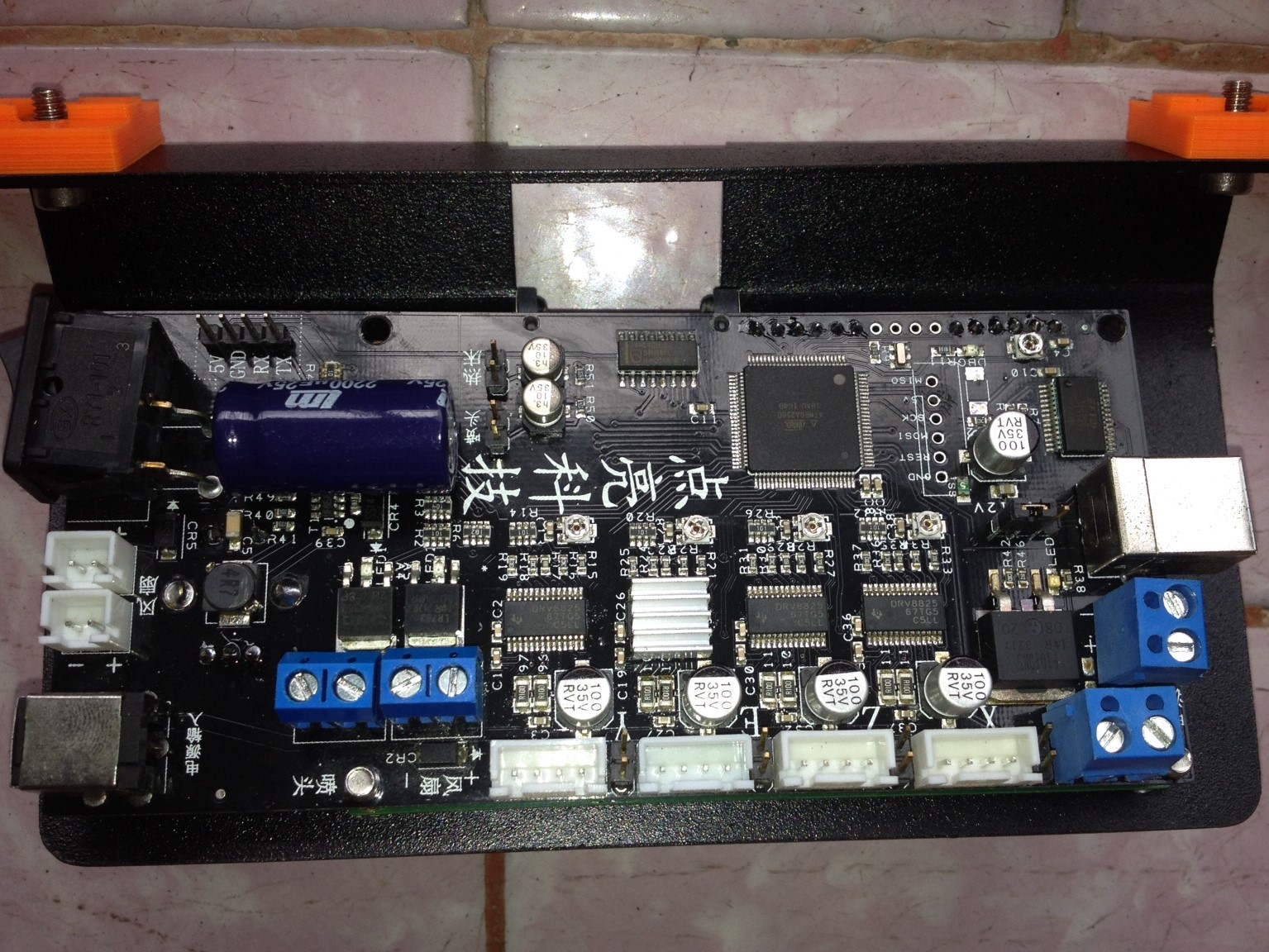
I have bought an used Delta mini 3d printer and this is the board that came with it. I don't know how to identify this board, there's no identification, only texts in chinese.
The board have a SDCard, a Rotary button encoder, an USB connector, an On/Off switch, all of them soldered in the board (ATMEGA 2560 is the main chip), the motors chips is all 8825.
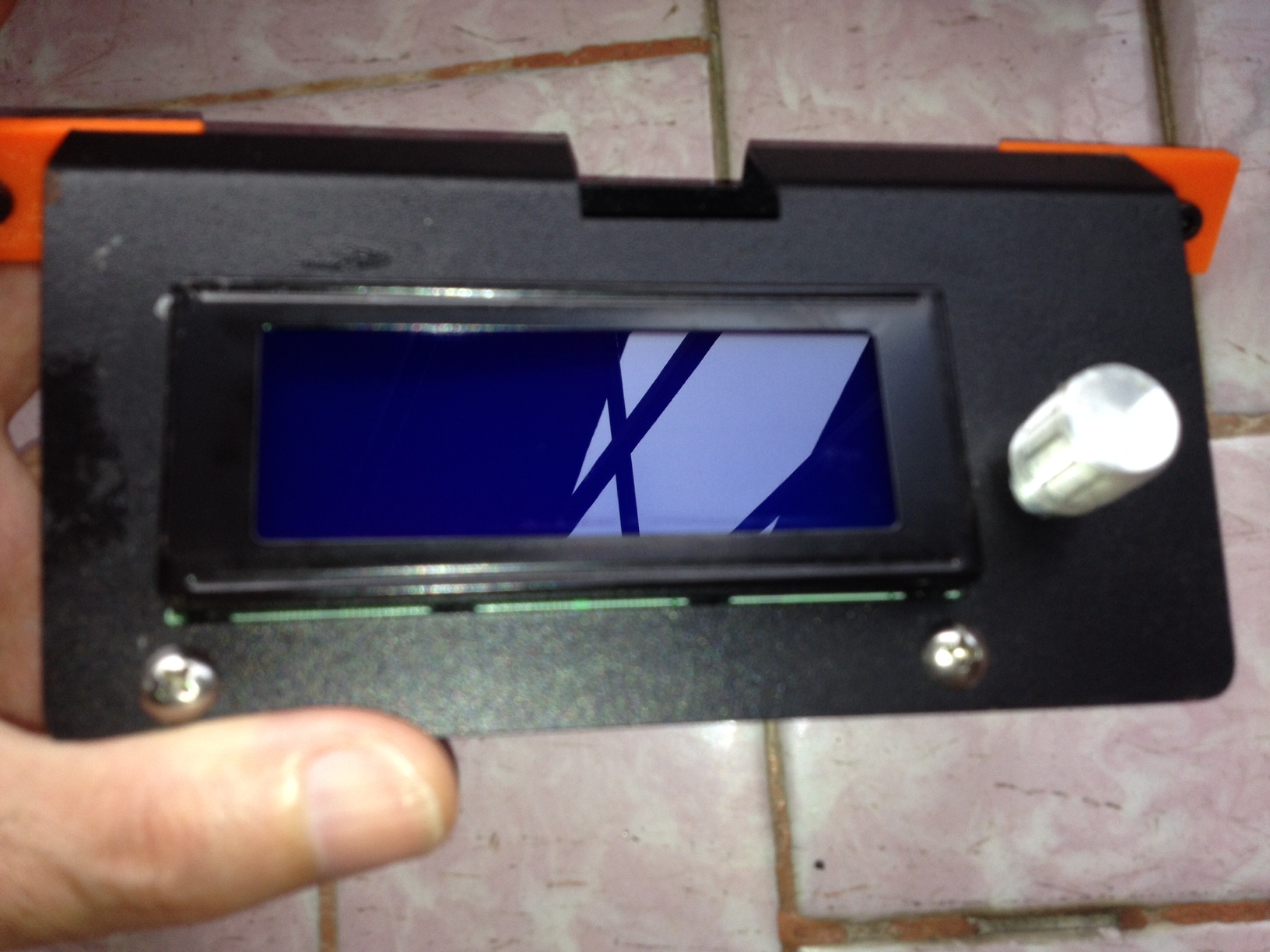
The LCD is write 2004A and is soldered in the main board.
I need to know how to setup this board and LCD in Marlin firmware, I want to update the Marlin in the 3d printer to a new version.
Please help me.
The board have a SDCard, a Rotary button encoder, an USB connector, an On/Off switch, all of them soldered in the board (ATMEGA 2560 is the main chip), the motors chips is all 8825.
The LCD is write 2004A and is soldered in the main board.
I need to know how to setup this board and LCD in Marlin firmware, I want to update the Marlin in the 3d printer to a new version.
Please help me.
|
Re: Please Help identify this board name and lcd controller December 10, 2017 03:01AM |
Registered: 8 years ago Posts: 5,232 |
When you connect the board to pronterface, there is a startup message. Does it say anything useful?
OTOH, the reason why the printer was sold might be the poor performance of the DRV8825 drivers. At least they have a bad reputation to skip steps when running slow. ( i.e. extruder )
Edited 1 time(s). Last edit at 12/10/2017 03:06AM by o_lampe.
OTOH, the reason why the printer was sold might be the poor performance of the DRV8825 drivers. At least they have a bad reputation to skip steps when running slow. ( i.e. extruder )
Edited 1 time(s). Last edit at 12/10/2017 03:06AM by o_lampe.
|
Re: Please Help identify this board name and lcd controller December 10, 2017 04:42AM |
Registered: 6 years ago Posts: 25 |
|
Re: Please Help identify this board name and lcd controller January 04, 2018 06:35PM |
Registered: 6 years ago Posts: 25 |
Ok. Nobody knows about this board.
I have tried every 2560 board available in Marlin, but none works fully. I discovery that the following PINS by myself:
PIN: 2 Port:E4 X_MAX_PIN
PIN: 58 Port:F4 Z_MAX_PIN
PIN: 65 Port:K3 Z_MIN_PIN
PIN: 13 TEMP_BED_PIN
PIN: 14 TEMP_SENSOR_0
Well not too much. I have used M43 gcode to read the PINS and test these pins and they worked.
How can I test the another PINS for stepper motors, heater and fan coolers ? Anyone could help me with this ?
|
Re: Please Help identify this board name and lcd controller January 04, 2018 08:13PM |
Admin Registered: 13 years ago Posts: 6,998 |
you should be able to visually trace some of them, take a high res scan (flat bed scanners are good for this, and blow it up as large as you can, both sides
you can also just use a multi meter on continuity to track where the step/direction and enable pins on the stepper drivers end up on the chip. Same with mosfet gate pins and any io pins
NB physical pin is not the same ardunio pins
see
NB the standard mega 2560 does not use all pins on the chip and your board might use those additional pins ... same as rambo does, needs a boards definition file to add the extra pins
see [raw.githubusercontent.com]
It adds in digital pins 70-83
Edited 2 time(s). Last edit at 01/04/2018 08:49PM by Dust.
you can also just use a multi meter on continuity to track where the step/direction and enable pins on the stepper drivers end up on the chip. Same with mosfet gate pins and any io pins
NB physical pin is not the same ardunio pins
see

NB the standard mega 2560 does not use all pins on the chip and your board might use those additional pins ... same as rambo does, needs a boards definition file to add the extra pins
see [raw.githubusercontent.com]
It adds in digital pins 70-83
Edited 2 time(s). Last edit at 01/04/2018 08:49PM by Dust.
|
Re: Please Help identify this board name and lcd controller January 09, 2018 01:36PM |
Registered: 6 years ago Posts: 25 |
Thank you very much, I have discovery several pins and almost done with mapping the pins for this board:
I'm posting what I found so if someone needing help identifying this board willl get the right pins:
//
// LCD Display output pins (I have configured in Configuration.h #define ULTRALCD and #define NEWPANEL), this board have the LCD soldered and only these settings are needed.
//
#define LCD_PINS_RS 49
#define LCD_PINS_ENABLE 48
#define LCD_PINS_D4 47
#define LCD_PINS_D5 46
#define LCD_PINS_D6 43
#define LCD_PINS_D7 42
// Rotary encoder
#define BTN_EN1 29
#define BTN_EN2 39
#define BTN_ENC 30
// Termistors
#define TEMP_0_PIN 14 // hotend thermistor
#define TEMP_BED_PIN 13 // heated bed thermistor
#define Z_STEP_PIN 63
#define Z_DIR_PIN 62
#define Z_ENABLE_PIN 64
#define E0_STEP_PIN 23
#define E0_DIR_PIN 22
#define E0_ENABLE_PIN 24
The following I didn't get them to work and I'm absolutelly sure the pins are correct it's clean visible in the board layout, I can only get to work with M17 enable and M18 disable the motors but not making them to move (turn left or right).
#define X_STEP_PIN 5
#define X_DIR_PIN 4
#define X_ENABLE_PIN 54
#define Y_STEP_PIN 26
#define Y_DIR_PIN 25
#define Y_ENABLE_PIN 27
|
Re: Please Help identify this board name and lcd controller January 11, 2018 03:50PM |
Registered: 6 years ago Posts: 25 |
More pins discovered for this board:
#define HEATER_0_PIN 8
#define HEATER_BED_PIN 9
#define FAN_PIN 7
#define SDSS 53
So this has been completed, all pins discovered. This board is not compatible with ANY BOARD included in Marlin, problably a customized board. Well, anyway all pins are good and if anyone has this, just give it a cool name and use these pinouts.
For my unluck the X/Y motors are not working, I don't know why tried everything but it just works the EN pin, not the step/dir pins.
|
Re: Please Help identify this board name and lcd controller January 12, 2018 04:12AM |
Registered: 8 years ago Posts: 5,232 |
|
Re: Please Help identify this board name and lcd controller January 12, 2018 12:06PM |
Registered: 6 years ago Posts: 25 |
|
Re: Please Help identify this board name and lcd controller January 13, 2018 03:44AM |
Registered: 8 years ago Posts: 5,232 |
|
Re: Please Help identify this board name and lcd controller January 13, 2018 05:07AM |
Registered: 6 years ago Posts: 25 |
Quote
o_lampe
Did you try to home the printer ( G28 ) or sent G92 X0 Y0 Z0 to fake it is homed? Otherwise Marlin won't move XYZ axis.
For the extruder you'd have to allow cold extrusion with M302 or heat up the hotend above ~170°C.
Yes, I tried the G92 X0 Y0 Z0 and also the M302 S0 to allow cold extrusion.
The Z and E works, but the X and Y didn't move to any direction, but if I try the M17 the X/Y motors hold it's position ( i can't move then by hand), and when I use the M18 they release (I can move then by hand), there's something in Marlin conflicting with the step and dir pins of these motors.
I tried yesterday to install the Repetier firmware and all the motors worked. But since I'm not so experienced with Repetier I didn't get the LCD to work. I will try to study more the Repetier in case I cant' get Marlin to work.
[Update] I got the LCD to work in Repetier, trying now to make the encoder to work. Repetier is a pain to setup lol.
Edited 1 time(s). Last edit at 01/13/2018 07:33AM by serandre.
|
Re: Please Help identify this board name and lcd controller January 13, 2018 09:00AM |
Registered: 6 years ago Posts: 25 |
GOT IT !!!
I'm feeling so stupid !!!
I was trying to move the X/Y motors before homing. So instead of homing (i was testing the board without the printer with just 1 motor connected) I just move the Z and all motors X/Y moved (it's configured as a Delta).
So, mission completed. :-)
Thank you for all the help I got from this board !!!
|
Re: Please Help identify this board name and lcd controller February 13, 2018 10:09AM |
Registered: 6 years ago Posts: 25 |
|
Re: Please Help identify this board name and lcd controller February 13, 2018 01:21PM |
Registered: 6 years ago Posts: 9 |
Hey, it's the guy from the youtube channel here. I managed to compile and upload the firmware to the printer, but I got a couple of problems.
The encoder, and apparently one of the limit switches are not working.
I've tested all the motors, fans, SD card, and LCD seem to be working.
Also, when trying to execute a G33 Delta Auto Level, the printer returns "ok" but nothing happens.
Edited 5 time(s). Last edit at 02/13/2018 02:21PM by lekey9000.
|
Re: Please Help identify this board name and lcd controller February 13, 2018 03:56PM |
Registered: 6 years ago Posts: 9 |
Managed to find the company that actually makes the boards, problem is, it's all in chinese. Want to try asking them for the files (that are available, but you have to install a ton of chinese stuff to download).
[shop106466425.world.taobao.com]
[shop106466425.world.taobao.com]
|
Re: Please Help identify this board name and lcd controller February 14, 2018 02:46PM |
Registered: 6 years ago Posts: 25 |
|
Re: Please Help identify this board name and lcd controller February 16, 2018 11:49AM |
Registered: 6 years ago Posts: 9 |
Thanks! The encoder works just fine with your configuration. One of the differences I did notice is that I set the power source wrong.
The problem now is that when I try to calibrate the printer or level the bed it basically auto homes, goes down a little, and then go all the way up.
Even after hitting the limit switches it still tries to go higher - that would eventually break the printer if I didn't turn it off before.
The motors work just fine when controlled manually and the auto home works as expected too. Any ideas?
Edited 1 time(s). Last edit at 02/16/2018 11:58AM by lekey9000.
|
Re: Please Help identify this board name and lcd controller February 16, 2018 03:48PM |
Registered: 6 years ago Posts: 25 |
Make sure you are using Marlin 1.1.7, I've tried version 1.1.8 and have several issues like these you had.
Using version 1.1.7, before trying to do any home or auto calibration type the following command in pronterface or any slice software that allows issuing gcodes (make sure you move the carriages away from the endstop limit switches):
M119
This command will show the endstop states: open or triggered
If any endstop shows triggered you will have to change it in the configuration.h where shows true to false for the endstop that shows open with M119:
#define X_MIN_ENDSTOP_INVERTING true // set to true to invert the logic of the endstop.
#define Y_MIN_ENDSTOP_INVERTING true // set to true to invert the logic of the endstop.
#define Z_MIN_ENDSTOP_INVERTING true // set to true to invert the logic of the endstop.
#define X_MAX_ENDSTOP_INVERTING true // set to true to invert the logic of the endstop.
#define Y_MAX_ENDSTOP_INVERTING true // set to true to invert the logic of the endstop.
#define Z_MAX_ENDSTOP_INVERTING true // set to true to invert the logic of the endstop.
#define Z_MIN_PROBE_ENDSTOP_INVERTING true // set to true to invert the logic of the probe.
After this you can home (G28) and auto calibration (G33) and auto level bed (G29);
Let me know if you got it to work.
Just remember that after you issue G33, issue M500 to save in EEPROM, the same must be done with G29 to save the settings. To make the G29 effective you must setup the init gcode in your slice software (ALWAYS after the G28 with the gcode M420 S1 - without this command the printer will not use the saved mesh).
The last thing you need to do is to setup the new ZERO height of the bed, if you don't to this your print head will crash in the bed. To do it issue a G28 to home and move just a little above the printer bed, and put a piece of paper above the bed. Slowly move the print head down in 0.1mm increments till the paper just can't move freely and get the position of it with M114 command. To setup new height get the vallue from configuration.h (DELTA_HEIGHT) and subtract from the Z value you've got from M114. Now you should setup the new Z height with the command M665 H. If you need more help you can see the Marlin gcodes here: [marlinfw.org]
Edited 1 time(s). Last edit at 02/16/2018 04:00PM by serandre.
|
Re: Please Help identify this board name and lcd controller February 17, 2018 03:21PM |
Registered: 6 years ago Posts: 9 |
|
Re: Please Help identify this board name and lcd controller February 17, 2018 04:24PM |
Registered: 6 years ago Posts: 25 |
Glad you have make it work.
Just a tip:
If you use the heat bed avoid to use it without a heat sink, my board mosfet has melted the solder after 6 months of use, use a heat sink on the heat bed mosfet (a large one that can fit in it) or use an external heat bed board, it's cheap from ML (about R$60), also use heat sink on the DRV8825's axes, this board only have heat sink on one DRV8825 chip (the extruder).
|
Re: Please Help identify this board name and lcd controller February 18, 2018 12:50PM |
Registered: 6 years ago Posts: 9 |
|
Re: Please Help identify this board name and lcd controller February 24, 2018 02:06PM |
Registered: 6 years ago Posts: 9 |
Okay, so I'm getting a lot of artifacts, trying to figure out why. Most of the time my prints have some kind of pattern all over them. Seems like something that should be fixed with configuration, did you have any similar problems?
I'm using 3 shells, so I'm pretty sure there's nothing to do with infill. I put a link to a picture of the issue below (since it's too large to attach)
[photos.app.goo.gl]
Edited 1 time(s). Last edit at 02/24/2018 02:07PM by lekey9000.
I'm using 3 shells, so I'm pretty sure there's nothing to do with infill. I put a link to a picture of the issue below (since it's too large to attach)
[photos.app.goo.gl]
Edited 1 time(s). Last edit at 02/24/2018 02:07PM by lekey9000.
|
Re: Please Help identify this board name and lcd controller February 25, 2018 09:26AM |
Registered: 6 years ago Posts: 25 |
These are blobs and zits (https://www.simplify3d.com/support/print-quality-troubleshooting/#blobs-and-zits) issue.
Make sure you have your extruder calibrate correctly. Bellow are some sites with info on calibrating extruders (you can find more on google search):
[mattshub.com]
[www.instructables.com]
After calibrating your extruder take a look at simplify3d print quality troubleshooting to see another settings that can help fix this issue.
I don't have any issue so far. I print at several type of filaments (PLA, ABS and PETG). You need to fine tune your print settings.
|
Re: Please Help identify this board name and lcd controller February 25, 2018 10:30AM |
Registered: 6 years ago Posts: 9 |
|
Re: Please Help identify this board name and lcd controller March 04, 2018 06:04PM |
Registered: 6 years ago Posts: 9 |
|
Re: Please Help identify this board name and lcd controller March 10, 2018 10:31AM |
Registered: 6 years ago Posts: 25 |
|
Re: Please Help identify this board name and lcd controller September 06, 2018 08:09AM |
Registered: 5 years ago Posts: 1 |
Thank you so very much!!!
I bought a delta from the same company and was struggling to update the firmware to a newer one, i've sent multiple emails, whatsapp messages and phone calls but their support is terrible, they only offered good support before my review on mercadolivre.
I had to make some small changes to the Configuration.h on the printable radius (my print volume is a 150 x 300 mm) and e-steps.
Also i had the same issue as lekey9000 with the print head stuttering, but changing the DELTA_SEGMENTS_PER_SECOND to 110 solved the issue.
Again, your contribution with the pinout of the board was invaluable!
|
Re: Please Help identify this board name and lcd controller September 22, 2018 08:14PM |
Registered: 6 years ago Posts: 25 |
UPDATE for this board: Dual filament printing using only one motor.
Using the things bellow:
[www.thingiverse.com]
and a filament y splitter in thingverse there're several of them.
In the board there's a RX/TX/GND/5V connector, you can use the GND/5V and the Part cooling fan (PWM) to control the servo. In this case you will disable the part cooling (not need for ABS), but if using PLA or another filament that needs cooling you can connect directly on the GND/12+ extra connector on the board and this way it will work always on, or use a switch to turn on/off the part cooling.
In the board config you need to include:
//
// Servos
//
#define SERVO0_PIN 7 // We will be using the part cooler fan pin to control the servo
In the board config change the line bellow:
#define FAN_PIN 7
to
#define FAN_PIN -1 // Disable the part cooling as we will be using the pin to servo0
In configuration.h change and uncomment
//#define NUM_SERVOS 4
to
#define NUM_SERVOS 1
That's it. From now you can control a servo and use the only extruder motor to print dual filament. Of course you need to make the tool change script to make it to work.
|
Re: Please Help identify this board name and lcd controller June 08, 2019 04:04PM |
Registered: 6 years ago Posts: 9 |
Very interesting upgrade serandre, thanks for sharing. After a lot of attempts and clogged nozzles, I finally managed to update Marlin. Currently using 1.1.9 with delta calibration, skew correction, and the load/ unload filament features. Quoting colatino: "Again, your contribution with the pinout of the board was invaluable!", the other settings like what kind of LCD and steppers this printer uses were also very useful.
The only hardware upgrade I've decided to do is to change to a full metal extruder - since the pins on the default plastic one breaks from time to time. Might get some TL Smoothers in the future, but still couldn't justify the price to myself.
The only hardware upgrade I've decided to do is to change to a full metal extruder - since the pins on the default plastic one breaks from time to time. Might get some TL Smoothers in the future, but still couldn't justify the price to myself.
Sorry, only registered users may post in this forum.