|
New replaceable stepper driver form-factor December 14, 2019 04:59PM |
Registered: 4 years ago Posts: 16 |
Greetings,
I've been designing my own controllers for about two years now. I really find the StepStick form factor to be limiting in two ways:
a) the board real estate is quite small and one has trouble fitting larger ICs like TMC2660 or TCM5161
b) the cooling on these is not great, because you have only one side exposed
On the other hand I have grown to appreciate the ability to quickly swap the drivers, when a new IC comes along with better features.
Here is a proposal:
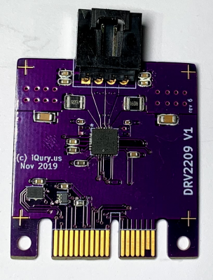
Design a new form factor using PCIe 1x slot as base. The drivers would stack vertically which would provide cooling on both sides. Can have a bit more latitude with respect to the driver board size (my current experiment is around 40x40mm). PCIe 1x has 36 pins, which allows for more interesting things like automatic chain ID assignment.
Here are some pictures of my experimental design:
Google photos shared album
For reference this is a link to the board and driver schematics.
GitHub.com
Thoughts?
I've been designing my own controllers for about two years now. I really find the StepStick form factor to be limiting in two ways:
a) the board real estate is quite small and one has trouble fitting larger ICs like TMC2660 or TCM5161
b) the cooling on these is not great, because you have only one side exposed
On the other hand I have grown to appreciate the ability to quickly swap the drivers, when a new IC comes along with better features.
Here is a proposal:
Design a new form factor using PCIe 1x slot as base. The drivers would stack vertically which would provide cooling on both sides. Can have a bit more latitude with respect to the driver board size (my current experiment is around 40x40mm). PCIe 1x has 36 pins, which allows for more interesting things like automatic chain ID assignment.
Here are some pictures of my experimental design:
Google photos shared album
For reference this is a link to the board and driver schematics.
GitHub.com
Thoughts?
|
Re: New replaceable stepper driver form-factor December 14, 2019 07:27PM |
Admin Registered: 13 years ago Posts: 6,998 |
|
Re: New replaceable stepper driver form-factor December 14, 2019 07:50PM |
Admin Registered: 13 years ago Posts: 6,998 |
Main issue is retention... there is nothing stopping these cards wiggling or being pulled out by gravity and or repeated thermal expansion and contraction.
Then their is looks... people like things in the so called golden ratio... with card like this on such small controller board, it just looks ugly!
Then their is looks... people like things in the so called golden ratio... with card like this on such small controller board, it just looks ugly!
|
Re: New replaceable stepper driver form-factor December 16, 2019 04:17AM |
Registered: 4 years ago Posts: 16 |
|
Re: New replaceable stepper driver form-factor December 16, 2019 12:52PM |
Registered: 9 years ago Posts: 978 |
|
Re: New replaceable stepper driver form-factor December 16, 2019 01:56PM |
Registered: 10 years ago Posts: 14,672 |
Quote
frankvdh
Instead of mounting them on the controller board, is there any reason not to mount them on the stepper itself?
Yes. Stepper motor drivers generate a lot of noise on the power and ground lines. This ground noise means that you couldn't send simple step, direction, enable and SPI or UART control signals to the stepper driver. You could send them over a noise-tolerant hardware protocol such as RS422 or RS485, but that would require a lot of wires.
A practical way to locate the stepper drivers close to the motor is to connect them to the main board using CAN-FD bus. CAN bus is very tolerant of ground noise and needs only 2 wires.
Duet 3 supports this architecture. At the TCT show last September, we demonstrated a tool-head board that controls the extruder motor, heater 2 fans, a filament monitor, Z probe and temperature sensors. Here's a Hermes/Hemera tool for an E3D Tool Changer fitted with the prototype.

There is of course a cost implication. The tool board needs a CAN-FD capable processor, 12V and 5V regulators, CAN transceiver chip, heater and fan mosfets etc. as well as the stepper driver. But it greatly reduces the number of wires to the tool head - just CAN and power are needed.
Large delta printer [miscsolutions.wordpress.com], E3D tool changer, Robotdigg SCARA printer, Crane Quad and Ormerod
Disclosure: I design Duet electronics and work on RepRapFirmware, [duet3d.com].
|
Re: New replaceable stepper driver form-factor December 16, 2019 10:32PM |
Registered: 4 years ago Posts: 16 |
Mounting the drives on the steppers is possible, but complicates the wiring. Now you have to carry power + a reliable means of communication (like CAN). This in turn makes the driver expensive. If you are doing drivers with integrated encoders, it makes more sense. Like in dc42's example you cram a bunch of functionality into the board to justify the communication chip cost.Quote
frankvdh
Instead of mounting them on the controller board, is there any reason not to mount them on the stepper itself?
With remote stepper drivers there is also the issue of synchronization of the motion. You want the axes to move together, which becomes a challenge if each driver has separate notion of stepping clock. None of these are unsolvable issues. It's just one of those things where you solve one thing and open another.
|
Re: New replaceable stepper driver form-factor December 17, 2019 06:15AM |
Admin Registered: 11 years ago Posts: 3,096 |
Quote
ghent360
Greetings,
I've been designing my own controllers for about two years now. I really find the StepStick form factor to be limiting in two ways:
a) the board real estate is quite small and one has trouble fitting larger ICs like TMC2660 or TCM5161
b) the cooling on these is not great, because you have only one side exposed
On the other hand I have grown to appreciate the ability to quickly swap the drivers, when a new IC comes along with better features.
Here is a proposal:
Design a new form factor using PCIe 1x slot as base. The drivers would stack vertically which would provide cooling on both sides. Can have a bit more latitude with respect to the driver board size (my current experiment is around 40x40mm). PCIe 1x has 36 pins, which allows for more interesting things like automatic chain ID assignment.
Here are some pictures of my experimental design:
Google photos shared album
For reference this is a link to the board and driver schematics.
GitHub.com
Thoughts?
I think your design is very elegant and much better than the older idea that Dust linked in his reply. Also, Dust's reaction was kinda direct/harsh, even though maybe partially true, it's also a bit subjective. I for one do not mind seeing the form factor. And the idea of allowing better cooling is indeed a great option. I think that if you manage to incorporate some kind of system to 'fix' the drivers in place, it might be a very useful system.
That said, I am seriously doubting if it is worth pursuing to design a new ecosystem of drivertype connections seeing the developments (especially with 32-bit boards) seem to take off in China right now. The supply seems to create the demand partially right now, instead of the demand creating the supply. BigTreeTech seems to listen to it's users after updating it's SKR 1.3 to the SKR 1.4.. I wonder where it's going to go in the coming two years. 8-bit is definitely going to be history. And so the Arduino mega will probably become obsolete. I suspect an overflow of 2nd-hand boards flooding ebay etc. With the Trinamic drivers becoming mainstream now there will also be an overflow of old allegro drivers. I am not an expert on technological development and it's impact on the replacement of older systems but I see it's going this way.
I was building a Prusa i3 clone having bought an old kit from a guy on a 2nd hand website and also had an original MK2.5S board but now that the SKR 1.4 has come out I decided to just ditch the original Prusa board and continue building the printer upon the new 32-bit board. It has more functionality and way more flexibility. Plus that I already have all the needed connectors and crimping tools specifically for the connections that the SKR boards have.
By designing the drivers and board in your philosophy I would really market it as a niche product for those that want high-performance application. For example those using Nema23 stepper motors that need more 'oomph'. Would it be possible to make an adapter so that you can still plug in the stepstick drivers into a small board that fits into the PCIe slots to keep the possibility of people adding older parts?
I'm just thinking out in the open here. Maybe you already thought about all of this, maybe I'm talking nonsense because I don't know what I'm talking about, anyway, I'm curious to hear.
http://www.marinusdebeer.nl/
|
Re: New replaceable stepper driver form-factor December 17, 2019 11:36PM |
Registered: 4 years ago Posts: 16 |
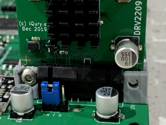
If you look at the driver picture there are two holes on both sides of the PCIe slot. I was planning on having a 3D printed plastic clip that would mount on the controller board and hold these in place so they don't wiggle out of place. I have the matching holes next to each PCIe slot.
I like SKR boards as well. They do try to make them very user friendly and are quite cost effective.
And to your last point - I was planning on making an adapter board for old style StepStick drivers, just haven't gotten to it yet.
I like SKR boards as well. They do try to make them very user friendly and are quite cost effective.
And to your last point - I was planning on making an adapter board for old style StepStick drivers, just haven't gotten to it yet.
|
Re: New replaceable stepper driver form-factor December 18, 2019 03:59AM |
Registered: 10 years ago Posts: 14,672 |
Two things worry me about that photo:
- What is the rated current of those PCIe edge connectors? What supply current can they handle reliably?
- That board doesn't include an electrolytic capacitor to absorb the back emf from the motor during deceleration. So you will be relying on there being one on the main board. It's farther away from the stepper driver chip than I would like, and of course the current has to flow through the edge connector. Also the typical 100uF capacitors on main boards are not sufficient for the larger motors and currents that your form factor appears to be aimed at. For example, on Duet 3 (which uses TMC5160 + external mosfets) we had to increase the capacitors to 220uF per driver, in order to restrict the overshoot to just a few volts. The capacitor should be included on the driver board, so that it can be correctly sized and so that the currents that flow between it and the driver don't go through the edge connector. This will if course make the driver board thicker, because you will need to allow for the capacitor being about 10mm high.
Large delta printer [miscsolutions.wordpress.com], E3D tool changer, Robotdigg SCARA printer, Crane Quad and Ormerod
Disclosure: I design Duet electronics and work on RepRapFirmware, [duet3d.com].
|
Re: New replaceable stepper driver form-factor December 18, 2019 04:29AM |
Admin Registered: 11 years ago Posts: 3,096 |
Why didn't you share your blog? 
[blog.pcbxprt.com]
Has some nice additional info!
http://www.marinusdebeer.nl/
[blog.pcbxprt.com]
Has some nice additional info!
http://www.marinusdebeer.nl/
|
Re: New replaceable stepper driver form-factor December 18, 2019 04:34AM |
Registered: 4 years ago Posts: 16 |
Thank you for the feedback. All raised points are valid. Some comments:
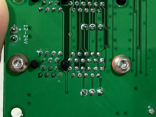
PCIe connectors are rated 1A/pin. There are 5 pins of power for each 24V and GND. The PCIe spec allow for 3A 3.3v power delivery over 4 pins, which I guess they would have tested for reliability.
There are 100uF caps on the controller board, with the idea that every driver needs them and it would be more economical to place them on the controller instead of each driver board. For drivers using heavy current a capacitor can be added to the board. Perhaps 100uF on the driver and 100uF on the controller would make for a good compromise?
The physical spacing between the boards in vertical position is 20mm. It should be sufficient for a decent size capacitor.
For really high current there is enough space on the top for separate power connector to each driver.
|
Re: New replaceable stepper driver form-factor December 18, 2019 07:15PM |
Registered: 4 years ago Posts: 16 |
|
Re: New replaceable stepper driver form-factor December 19, 2019 04:30AM |
Registered: 10 years ago Posts: 14,672 |
For TMC2660 I suggest 2 x 1uF ceramic (one on each side) plus 100uF electrolytic. It's TMC5160 and similar drivers + external mosfets that may need more than 100uF, depending on current.
Large delta printer [miscsolutions.wordpress.com], E3D tool changer, Robotdigg SCARA printer, Crane Quad and Ormerod
Disclosure: I design Duet electronics and work on RepRapFirmware, [duet3d.com].
Large delta printer [miscsolutions.wordpress.com], E3D tool changer, Robotdigg SCARA printer, Crane Quad and Ormerod
Disclosure: I design Duet electronics and work on RepRapFirmware, [duet3d.com].
|
Re: New replaceable stepper driver form-factor January 03, 2020 12:58PM |
Registered: 7 years ago Posts: 270 |
As part of my new year resolution I resumed a long lost project so I've read a thing or two about tmc2660. Trinamic recommends 100uF per Ampere (though IIRC they do not follow their rule with BOB boards). Cap should be low ESR so it has to be mounted as close to the driver as possible. One advantage of going with larger cap is lower ESR. Smaller 100nF cap should be even closer, 1-2mm from VS pin.
@dc42 are the 1uF that you recommend for VSA and VSB? I have not seen those on trinamic 2660 schematics but do see them (although 100nF) on tmc2130 which is from the same family as tmc5160.
Btw, Trinamic Appnotes are great if you have not seen them already: [www.trinamic.com] The one about good ground was especially illuminating.
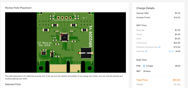
@ghent360, This is an interesting project. I think that plug-gable form factor is a great feature. Last time I checked PCIe connector added to the cost substantially due to board thickness requirement and special plating, but $6.59 per assembled board is very good. I assume tmc2660 is $2 more? Overall, I think the most important, these days, is the software so I'm curious which processor have you picked.
Also, I'm curious if you considered right angle 2.54 pin header and why you have decided against it? As to the card itself, I'm not sure if that is possible routing wise, but it would be better if motor connector was on the side of the card, not the top for two reasons: less strain on the whole board/PCIe and, arguably, better cable management.
@dc42 are the 1uF that you recommend for VSA and VSB? I have not seen those on trinamic 2660 schematics but do see them (although 100nF) on tmc2130 which is from the same family as tmc5160.
Btw, Trinamic Appnotes are great if you have not seen them already: [www.trinamic.com] The one about good ground was especially illuminating.
@ghent360, This is an interesting project. I think that plug-gable form factor is a great feature. Last time I checked PCIe connector added to the cost substantially due to board thickness requirement and special plating, but $6.59 per assembled board is very good. I assume tmc2660 is $2 more? Overall, I think the most important, these days, is the software so I'm curious which processor have you picked.
Also, I'm curious if you considered right angle 2.54 pin header and why you have decided against it? As to the card itself, I'm not sure if that is possible routing wise, but it would be better if motor connector was on the side of the card, not the top for two reasons: less strain on the whole board/PCIe and, arguably, better cable management.
|
Re: New replaceable stepper driver form-factor January 03, 2020 01:08PM |
Registered: 10 years ago Posts: 14,672 |
Quote
newbob
@dc42 are the 1uF that you recommend for VSA and VSB? I have not seen those on trinamic 2660 schematics but do see them (although 100nF) on tmc2130 which is from the same family as tmc5160.
The partial schematic on page 44 of the rev. 1.05 datasheet shows 10uF on each of VSA and VSB. But 20uF total isn't enough to suppress overshoot adequately when the motors are disabled, bearing in mind that the TMC2660 is rated at only 30V. On Duet 2 we use one 1uF ceramic and one 100uF electrolytic per TMC2660.
And yes, good grounding is essential so that the current sensing circuitry sees only the voltage across the sense resistors.
Edited 1 time(s). Last edit at 01/03/2020 01:10PM by dc42.
Large delta printer [miscsolutions.wordpress.com], E3D tool changer, Robotdigg SCARA printer, Crane Quad and Ormerod
Disclosure: I design Duet electronics and work on RepRapFirmware, [duet3d.com].
|
Re: New replaceable stepper driver form-factor January 03, 2020 01:30PM |
Registered: 7 years ago Posts: 270 |
Thanks @dc42 for pointing that out. Interestingly, that partial schematic does not include 10nF caps on SRA and SRB lines.
@ghent360 I saw your blog - your controller board is two layer PCB? That is impressive - I would have thought that's impossible with ST32F running at 180MHz
EDIT: Having second look, both Trinamic datasheets (for TMC2130 and TMC2660) call for 100nF capacitors. 1uF caps are not in the Trinamic design recommendations.
Edited 2 time(s). Last edit at 01/03/2020 06:39PM by newbob.
|
Re: New replaceable stepper driver form-factor January 03, 2020 11:00PM |
Registered: 4 years ago Posts: 16 |
Happy 2020 everyone. It is the year of the aluminum profile.
Connector choice:
There are many options on the table. I found PCIe connector for about $0.30 per connector. Uses standard 1.6mm board thickness. Pin headers have lower pin density and it is hard to find cheap ones with polarity locking.
Re: motor connector placement
On the controller board itself. Decided against that, because one has to shuttle the current from the driver back to the controller PCB, putting more requirements on the board to board interconnect.
Top vs side. I wanted the option to use 40 or 60mm fans to blow from the side of the driver to provide extra cooling and the cables would get in the way of that.
Agreed it is not ideal and quite ugly as it is. Happy to entertain options.
Re: tmc2660 price
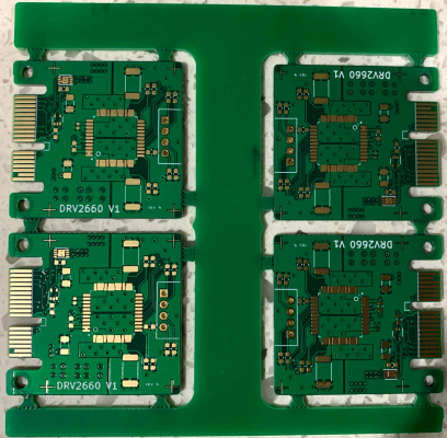
The 2660 uses 4 layer PCB, that would add about $2.50 per board in order quantities of 10. The driver IC is +$3 and also it needs higher power rated current sense resistors. So around $13 in small quantities is more realistic expectation. There are opportunities to save on the board cost though - the price break is for 10x10cm boards, and one can fit 4 drivers in that space.
Connector choice:
There are many options on the table. I found PCIe connector for about $0.30 per connector. Uses standard 1.6mm board thickness. Pin headers have lower pin density and it is hard to find cheap ones with polarity locking.
Re: motor connector placement
On the controller board itself. Decided against that, because one has to shuttle the current from the driver back to the controller PCB, putting more requirements on the board to board interconnect.
Top vs side. I wanted the option to use 40 or 60mm fans to blow from the side of the driver to provide extra cooling and the cables would get in the way of that.
Agreed it is not ideal and quite ugly as it is. Happy to entertain options.
Re: tmc2660 price
The 2660 uses 4 layer PCB, that would add about $2.50 per board in order quantities of 10. The driver IC is +$3 and also it needs higher power rated current sense resistors. So around $13 in small quantities is more realistic expectation. There are opportunities to save on the board cost though - the price break is for 10x10cm boards, and one can fit 4 drivers in that space.
|
Re: New replaceable stepper driver form-factor January 04, 2020 07:42PM |
Registered: 7 years ago Posts: 270 |
Just FYI, for reference, Panucat TMC2660 driver board is $13.50 + shipping. [panucattdevices.freshdesk.com]
There are, of course, some pluses to your solution, namely opensource project, a configuration that is cheaper to fix or upgrade or expand, and probably supports more stepper motors.
There are, of course, some pluses to your solution, namely opensource project, a configuration that is cheaper to fix or upgrade or expand, and probably supports more stepper motors.
|
Re: New replaceable stepper driver form-factor January 06, 2020 12:05AM |
Registered: 4 years ago Posts: 16 |
|
Re: New replaceable stepper driver form-factor January 06, 2020 01:13PM |
Registered: 7 years ago Posts: 270 |
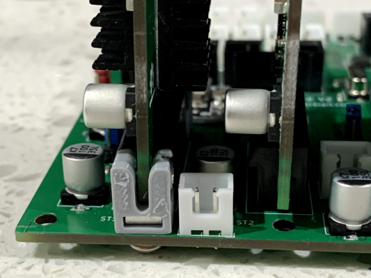
Maybe DIMM like clip would work better, although, it would have to rely on plasticity of the printed part and groves instead of holes may add cost to PCB.
Edited 2 time(s). Last edit at 01/06/2020 01:20PM by newbob.

Edited 2 time(s). Last edit at 01/06/2020 01:20PM by newbob.
|
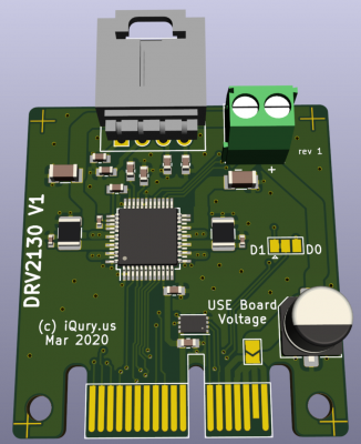
Re: New replaceable stepper driver form-factor March 01, 2020 09:28PM |
Registered: 4 years ago Posts: 16 |
|
Re: New replaceable stepper driver form-factor March 03, 2020 01:56PM |
Registered: 7 years ago Posts: 270 |
Great addition and definitively adds to boards flexibility. I suppose current limiting and polarity protection would happen outside of the board? One thing I would move is the electrolytic capacitor to be closer to the IC and after onboard power IN. Probably a challenge to route though -maybe put the cap or screw terminal on the bottom layer side?
Edited 1 time(s). Last edit at 03/03/2020 01:57PM by newbob.
Edited 1 time(s). Last edit at 03/03/2020 01:57PM by newbob.
|
Re: New replaceable stepper driver form-factor March 06, 2020 10:35PM |
Registered: 4 years ago Posts: 16 |
|
Re: New replaceable stepper driver form-factor March 07, 2020 02:48AM |
Registered: 10 years ago Posts: 14,672 |
The placement of the electrolytic capacitor isn't critical so long as there are ceramic ones close to the chip on the same power fail.
Large delta printer [miscsolutions.wordpress.com], E3D tool changer, Robotdigg SCARA printer, Crane Quad and Ormerod
Disclosure: I design Duet electronics and work on RepRapFirmware, [duet3d.com].
Large delta printer [miscsolutions.wordpress.com], E3D tool changer, Robotdigg SCARA printer, Crane Quad and Ormerod
Disclosure: I design Duet electronics and work on RepRapFirmware, [duet3d.com].
|
Re: New replaceable stepper driver form-factor March 22, 2020 11:21PM |
Registered: 4 years ago Posts: 16 |
I did some modifications on this open source Gerber panelizer tool, so I can produce BOM and crentroid files for JLCPCB. Finally managed to get it to work. I created this 10x10cm panel for the TMC2660 driver.
When you order 5 panels (aka 20 drivers) the cost is about $9.5 per driver (with shipping). If I order 10 panels, it goes down to $7.5 per driver.
Btw. I did some thermal tests on the TMC2660 driver and with 2.7A load it was running at 72C at standstill and 56C while the motor was running.
Edited 1 time(s). Last edit at 03/22/2020 11:23PM by ghent360.
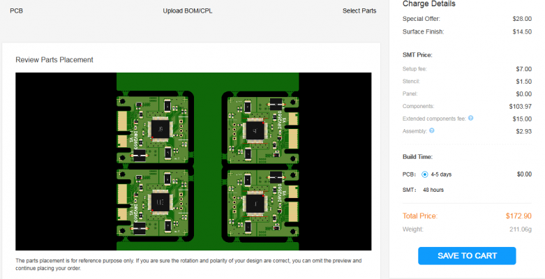
Sorry, only registered users may post in this forum.