Motherboard i2c (Gen3)
Posted by Milly
|
Motherboard i2c (Gen3) June 12, 2011 05:35AM |
Registered: 14 years ago Posts: 47 |
Hi,
I am trying to integrate a LCD onto my gen 3 motherboard using i2c. I've not modified the firmware yet but have tried connecting the LCD controller to the i2c connectors on the motherboard and found that the display is not recognising the existence of the i2c bus (I'm using a BV4618 so the screen should display the i2c address on poweron). The controller detects the presence of i2c by checking for a high across the SDA line, when I checked this myself the pin seems to be held low all the time. Does the extruder controller actually communicate with the motherboard via i2c or RS485 as the printer seems to work fine otherwise?
Milly.
|
Re: Motherboard i2c (Gen3) June 12, 2011 06:18AM |
Admin Registered: 17 years ago Posts: 7,879 |
The RS485 bus is use for serial commands and the I2C lines are step and direction, not I2C serial comms.
[www.hydraraptor.blogspot.com]
[www.hydraraptor.blogspot.com]
|
Re: Motherboard i2c (Gen3) June 12, 2011 06:44AM |
Registered: 14 years ago Posts: 47 |
|
Re: Motherboard i2c (Gen3) June 12, 2011 09:43AM |
Admin Registered: 17 years ago Posts: 7,879 |
I think so as Makerbot don't use those two pins for extruder control.
[www.hydraraptor.blogspot.com]
[www.hydraraptor.blogspot.com]
|
Re: Motherboard i2c (Gen3) June 13, 2011 02:54AM |
Registered: 14 years ago Posts: 3,742 |
With the standard RepRap firmware you can use the the X and Y max end stop lines for step and direction for the extruder and then the other pins can be used for I2C as originally intended (almost no one uses the max end stops).
Also take a look at LCD+Keypad Control Panel for Makerbot by Revar on Thingiverse.
Bob Morrison
Wörth am Rhein, Germany
"Luke, use the source!"
BLOG - PHOTOS - Thingiverse
Also take a look at LCD+Keypad Control Panel for Makerbot by Revar on Thingiverse.
Bob Morrison
Wörth am Rhein, Germany
"Luke, use the source!"
BLOG - PHOTOS - Thingiverse
|
Re: Motherboard i2c (Gen3) June 13, 2011 08:39AM |
Registered: 14 years ago Posts: 47 |
Thanks for the replies. I have done a quick test with the Makerbot firmware and the i2c interface worked well enough for the LCD screen to display its address. I did not try operating the extruder with the new firmware on it, but will look at Bob's solution as it could potentially mean I can run the newer reprap firmware as well.
The link is interesting, very similar to what I am trying to do but I will be mounting the keypad and display on the unit itself and have used a different controller. I will definitely look at the source code to see how he has implemented the display/keypad in the firmware.
Thanks!
Milly.
The link is interesting, very similar to what I am trying to do but I will be mounting the keypad and display on the unit itself and have used a different controller. I will definitely look at the source code to see how he has implemented the display/keypad in the firmware.
Thanks!
Milly.
|
Re: Motherboard i2c (Gen3) June 22, 2011 03:17PM |
Registered: 14 years ago Posts: 47 |
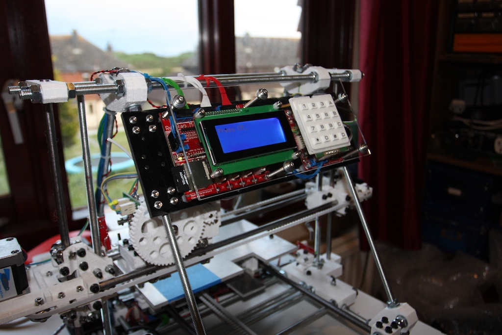
Here's a quick update on progress. I've now attached the display and keyboard to the reprap, it sits nicely over the motherboard and extruder boards in some transparent acrylic. I decided to mount it so that it was still possible to get behind to plug/unplug leads and reach the reset buttons on each board. I've also rewired the extruder so that it takes a feed from the x/y endstops rather than the pins used for i2c, although I've yet to change the firmware to free up the interface hence the reason the display is showing some random message.
Thats the easy part done, now time to hack the firmware and get some useful information on the LCD!
Milly.
Thats the easy part done, now time to hack the firmware and get some useful information on the LCD!
Milly.
|
Re: Motherboard i2c (Gen3) June 22, 2011 03:59PM |
Registered: 14 years ago Posts: 47 |
A quick look at the pins.h file shows the following:
#define X_STEP_PIN (byte)15
#define X_DIR_PIN (byte)18
#define X_MIN_PIN (byte)20
#define X_MAX_PIN (byte)21
#define X_ENABLE_PIN (byte)19
#define Y_STEP_PIN (byte)23
#define Y_DIR_PIN (byte)22
#define Y_MIN_PIN (byte)25
#define Y_MAX_PIN (byte)26
#define Y_ENABLE_PIN (byte)19
#define Z_STEP_PIN (byte)29
#define Z_DIR_PIN (byte)30
#define Z_MIN_PIN (byte)2
#define Z_MAX_PIN (byte)1
#define Z_ENABLE_PIN (byte)31
// Heated bed - TODO: reassign these
#define BED_HEATER_PIN (byte)3
#define BED_TEMPERATURE_PIN (byte)1
//extruder pins
#define EXTRUDER_0_MOTOR_SPEED_PIN (byte)12
#define EXTRUDER_0_MOTOR_DIR_PIN (byte)16
#define EXTRUDER_0_HEATER_PIN (byte)14
#define EXTRUDER_0_FAN_PIN (byte)3
#define EXTRUDER_0_TEMPERATURE_PIN (byte)4 // Analogue input
#define EXTRUDER_0_VALVE_DIR_PIN (byte)17
#define EXTRUDER_0_VALVE_ENABLE_PIN (byte)13 // Valve needs to be redesigned not to need this
#define EXTRUDER_0_STEP_ENABLE_PIN (byte)3 // 3 - Conflicts with the fan; set -ve if no stepper
Am I correct in thinking I can get away with swapping the EXTRUDER_0_MOTOR_DIR_PIN (currently 16) over to X_MAX_PIN (currently at 21) and the EXTRUDER_0_VALVE_DIR_PIN (currently at 17) with the Y_MAX_PIN (currently at 26). I'm assuming pins 16 and 17 are the ones the 644p uses for i2c but may be wrong. Also, given that I am not intending to use the X/Y max pins, what do I set them to (-1 maybe?)??
Thanks!
Milly.
|
Re: Motherboard i2c (Gen3) June 23, 2011 07:05AM |
Registered: 14 years ago Posts: 3,742 |
YES, that is exactly what I am planning on doing!
Your mechanical mount looks very nice but how are you going to access the Motherboard and Extruder reset buttons?
I was planning on having a flip up panel that would be MDF (so only the LCD and Keyboard are visible) and then when I want to change the SC card or access the reset buttons I can simply flip the panel up.
Bob Morrison
Wörth am Rhein, Germany
"Luke, use the source!"
BLOG - PHOTOS - Thingiverse
|
Re: Motherboard i2c June 23, 2011 11:43AM |
Registered: 14 years ago Posts: 47 |
Bob,
I decided on transparent acrylic because it allows you to see the status LED's on the two boards, and also because I worked so hard to learn SMD soldering techniques and those two boards are the fruits of my labour and I wanted them on display!
There is sufficient distance between the acrylic and the boards that I can easily reach the reset buttons, although I am hoping I won't be needing them too often! In fact I can plug/unplug all the leads and even get a soldering iron in if required so I am happy with the setup.
Just got to sort out the firmware and a rogue capacitor that came off the extruder board!
Milly
|
Re: Motherboard i2c June 23, 2011 01:00PM |
Registered: 14 years ago Posts: 3,742 |
Hmmm... Maybe I'll mount mine the same way! :-)
What are the length of the spacers you are using?
Bob Morrison
Wörth am Rhein, Germany
"Luke, use the source!"
BLOG - PHOTOS - Thingiverse
What are the length of the spacers you are using?
Bob Morrison
Wörth am Rhein, Germany
"Luke, use the source!"
BLOG - PHOTOS - Thingiverse
|
Re: Motherboard i2c (Gen3) June 23, 2011 02:07PM |
Registered: 14 years ago Posts: 47 |
|
Re: Motherboard i2c (Gen3) June 23, 2011 04:19PM |
Registered: 14 years ago Posts: 47 |
Well, as I mentioned, I lost a capacitor whilst I was installing the display and keyboard. I knocked the thing and it fell off taking a piece of the pcb with it! The capacitor in question is C1 which is a 100uf one I am assuming is for smoothing of the voltage supply. There is an additional 100uf capacitor (C2) across Vcc and GND as well as two 100nf capacitors. Do these extra capacitors provide enough redundancy so that I can forget about C1? I strategically placed some solder across the PCB to reconnect the VCC line with the output of the 7805 and the controller seems to be working fine. Is it safe to continue operating without C1?
Oh yes, are my pin changes in the code above correct; am I correct in thinking the firmware sends EXTRUDER_0_MOTOR_DIR_PIN and EXTRUDER_0_VALVE_DIR_PIN through the pins normally used for i2c?
Cheers,
Milly!
Oh yes, are my pin changes in the code above correct; am I correct in thinking the firmware sends EXTRUDER_0_MOTOR_DIR_PIN and EXTRUDER_0_VALVE_DIR_PIN through the pins normally used for i2c?
Cheers,
Milly!
|
Re: Motherboard i2c (Gen3) June 26, 2011 05:44PM |
Registered: 14 years ago Posts: 47 |
|
Re: Motherboard i2c (Gen3) June 27, 2011 01:31PM |
Registered: 13 years ago Posts: 1,352 |
I assume you are talking about EC2.2, where C1 (typically 100uF) is the electrolitic input capacitor right before 7805 and C2 is on the output from it (maybe10uF would of been enough but its 100uF also). One is for input and one is for output, and voltage regulator could work without any capacitor at all, but usually they are there to improve things, stability, cancel some noise etc.
If you dont have a fresh cap, imo get some 100uF cap from any board that otherwise would go to garbage, is common value and can be found easily. Otherise try without, but i think the micro adc is fairly sensitive to noise - i guess enough for some boards to have LC filter for it.
If you dont have a fresh cap, imo get some 100uF cap from any board that otherwise would go to garbage, is common value and can be found easily. Otherise try without, but i think the micro adc is fairly sensitive to noise - i guess enough for some boards to have LC filter for it.
|
Re: Motherboard i2c (Gen3) June 29, 2011 04:33AM |
Registered: 14 years ago Posts: 3,742 |
@Milly: Do you happen to have an .SVG file of your LCD/Keypad mounting plate?
Bob Morrison
Wörth am Rhein, Germany
"Luke, use the source!"
BLOG - PHOTOS - Thingiverse
Bob Morrison
Wörth am Rhein, Germany
"Luke, use the source!"
BLOG - PHOTOS - Thingiverse
|
Re: Motherboard i2c (Gen3) June 30, 2011 04:44AM |
Registered: 14 years ago Posts: 47 |
Hi Bob,
I still have the file I used to get the perspex cut, not sure if its SVG. My computer is currently with Apple at the moment as it had the dreaded vertical white lines problem on the LCD. In fairness to Apple they immediately offered to repair it free when I took it to the Genius bar and thats despite it being 5 years old and the fact they knew I had taken it apart to swap out the hard disk. Should have it back today or tomorrow so will upload the file then.
Milly.
|
Re: Motherboard i2c (Gen3) June 30, 2011 05:04AM |
Registered: 14 years ago Posts: 3,742 |
@Milly: Great. Thanks in advance!
Bob Morrison
Wörth am Rhein, Germany
"Luke, use the source!"
BLOG - PHOTOS - Thingiverse
Bob Morrison
Wörth am Rhein, Germany
"Luke, use the source!"
BLOG - PHOTOS - Thingiverse
|
Re: Motherboard i2c (Gen3) July 01, 2011 02:42PM |
Registered: 14 years ago Posts: 47 |
|
Re: Motherboard i2c (Gen3) July 01, 2011 04:04PM |
Registered: 14 years ago Posts: 3,742 |
Perfect - THANKS!
Bob Morrison
Wörth am Rhein, Germany
"Luke, use the source!"
BLOG - PHOTOS - Thingiverse
Bob Morrison
Wörth am Rhein, Germany
"Luke, use the source!"
BLOG - PHOTOS - Thingiverse
Sorry, only registered users may post in this forum.