PCB v1.3.0. problems
Posted by Satuna
|
PCB v1.3.0. problems January 23, 2008 02:23PM |
Registered: 16 years ago Posts: 92 |
Hi all,
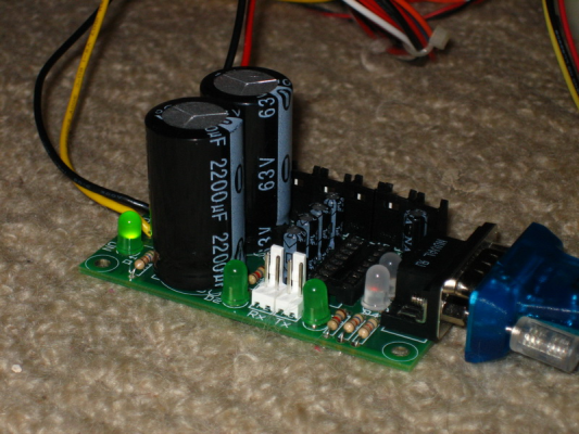
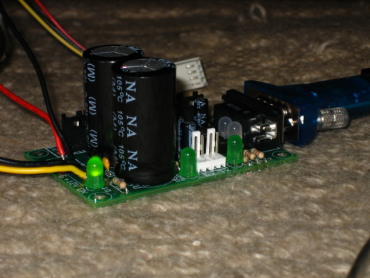
I have finished soldering my first board: PCB 1.3.0. I have come across a little problem though as you can see in the pics.
The first test stage was ok:
- no smoke
- the green LED lights up when I turn on the power
- and 5V between pins 15 and 16 on the socket
However, from here on it was a mess: when I connect the serial port only one biLED lights up which is red and not green anyway. (I may have messed up the polarity...) The second led does not light up at all even if I short Rx and Tx... And there is no echo in HyperTerminal with the communication board. Without the board the serial cable works well (echoes in hyperterminal) if I short pins 2 and 3.
Some more stuff:
Pin 15 to 16: 5V. This is OK.
Pin 15 to 14: This shoud be: -7 to -15V. It is 0V in my case...
Pin 15 to 13: 0V instead of 0V.
Pin 15 to 12: 3.6V instead of 5V.
Pin 15 to 11: 3.3 V instead of 4 to 4.5V.
Anyone has an idea what the hell is going on on this board? I use an AT power supply direcly which makes 10.96V instead of 12V but I think it should not be a problem at this stage...
Thanks,
Adam
|
Re: PCB v1.3.0. problems January 23, 2008 04:02PM |
Admin Registered: 17 years ago Posts: 1,487 |
|
Re: PCB v1.3.0. problems January 23, 2008 04:20PM |
Registered: 16 years ago Posts: 92 |
|
Re: PCB v1.3.0. problems January 23, 2008 06:15PM |
Registered: 16 years ago Posts: 270 |
As far as I can see from the Pic there is no Max232 fitted just an empty socket the echo test requires the MAX232
Ian
[www.bitsfrombytes.com]
Ian
[www.bitsfrombytes.com]
|
Re: PCB v1.3.0. problems January 23, 2008 07:04PM |
Admin Registered: 17 years ago Posts: 1,487 |
|
Re: PCB v1.3.0. problems January 24, 2008 01:16PM |
Registered: 16 years ago Posts: 92 |
|
Re: PCB v1.3.0. problems January 24, 2008 01:17PM |
Registered: 16 years ago Posts: 92 |
|
Re: PCB v1.3.0. problems January 24, 2008 04:46PM |
Admin Registered: 17 years ago Posts: 1,487 |
|
Re: PCB v1.3.0. problems February 03, 2008 10:39PM |
Registered: 16 years ago Posts: 37 |
Hey,
As someone else putting together the electronics for the first time, I had the same problem. The disconnect in the documentation is that for the initial power test, the MAX232 chip is out, then you put it in for the communications test, then if you have problems (as I did, on account of minicom, but I assumed it was a problem with my soldering), go to the debugging. The voltage tests between the different pins, though, do not explicitly state whether you are testing with the MAX232 out or in. In retrospect, given the context, that was obvious, but for someone without much electronics experience or intuition, a helpful clarifying sentence may help in the debugging section.
On a tangentially related aside, minicom (on Ubuntu), is not what I would call trivial as far as testing the echo. I played around with a half dozen settings to try and send text to have it echo back in command. After looking in the man pages and at nophead's 1.2 testing and debugging, I am still unclear and having problems (hopefully not related to the fact that ubuntu is being run virtually on parallels). A bit of documentation here would also be useful in the future, unless I'm just stupid, which is quite possible.
Thanks!
|
Re: PCB v1.3.0. problems February 04, 2008 03:49AM |
Registered: 16 years ago Posts: 92 |
|
Re: PCB v1.3.0. problems February 20, 2008 09:14AM |
Registered: 16 years ago Posts: 35 |
Hi,
I am having a similar problem.
Without the max232 chip in - the board lights up only the power LED
With the max232 chip in one of the bipolar LEDs lights up a faint green.
Plugging the serial cable into a live serial port makes no difference.
In my case I have not yet tested the serial port as suggested, however I have used it to program a PIC, which suggests it work fine?
Any suggestions?
Next I will be at the stage of shorting the TX and RX connections. But how do i do this? Place 2 jumpers on the two connectors?
Cheers,
Joe
|
Re: PCB v1.3.0. problems February 20, 2008 09:36AM |
Registered: 16 years ago Posts: 92 |
Joe,
Firstly, check soldering of the other bipolar LED.
Then, test your cable anyway by shorting pin 2 and 3. Just to make sure. It takes 2 seconds and you know if your cable is working at least.
Then check voltages, it helps a lot too.
Then if you still having problems do this: turn off everything. Take your MAX out. Put it back, if you have a spare put that one back instead and turn the power on again. (In my case the first MAX did not work, maybe the too many take-out-put-back did not help it a lot :-)) I simply solved my problem by buying a new MAX chip.
Shorting is not done with jumpers because in that way you would shorten the two pins on each connector. Instead what you have to do is short the corresponding pins on TX and RX. Right pin on TX goes on the right on RX and vica versa.
Hope this helps,
Adam
|
Re: PCB v1.3.0. problems February 20, 2008 09:39AM |
Registered: 16 years ago Posts: 35 |
Sorry, only registered users may post in this forum.


