V1 Engineering's Piper
Posted by Roberts_Clif
|
Re: V1 Engineering's Piper May 27, 2019 12:24PM |
Registered: 5 years ago Posts: 25 |
Makers here bought a fruit/vegetable/herb/meat dryer and the size just matches. XDD
[www.aliexpress.com]
or dry cabinet for DSLR for long term purpose.
SecKit, all-metal linear rail CoreXY kit
[seckit3dp.design]
[www.aliexpress.com]
or dry cabinet for DSLR for long term purpose.
SecKit, all-metal linear rail CoreXY kit
[seckit3dp.design]
|
Re: V1 Engineering's Piper May 27, 2019 01:38PM |
Registered: 6 years ago Posts: 1,863 |
Quote
Ernest1122
Makers here bought a fruit/vegetable/herb/meat dryer and the size just matches. XDD
[www.aliexpress.com]
or dry cabinet for DSLR for long term purpose.
Thank you Ernest1122 : Though if you would have read I Noted :
I Do not have any Filament moisture Problems : the problem is the Raspberry Pi 2 using Octolapse with a Web Cam This uses all available processing power which somehow cause the blemishes.
I have proved this as the only print that had blemishes was the one that I used in this Time lapsed video.
Still only missing one item have not picked up the Conduit, to many thing on my plate. Have not forgot.
Edited 1 time(s). Last edit at 05/27/2019 01:38PM by Roberts_Clif.
Computer Programmer / Electronics Technician
|
Re: V1 Engineering's Piper May 27, 2019 01:40PM |
Registered: 6 years ago Posts: 1,863 |
Quote
Shank man
Irregardless those are some damn nice prints. I really need to make some enclosures for my printers.
Thank you they are some nice prints for my first ABS prints. Almost better than some of my PLA prints.
Edited 1 time(s). Last edit at 05/27/2019 01:41PM by Roberts_Clif.
Computer Programmer / Electronics Technician
|
Re: V1 Engineering's Piper June 01, 2019 11:11AM |
Registered: 6 years ago Posts: 1,863 |
The build is going quite slowly, simply because when I started this project, was hoping to use some of my spare 3D Printers parts.
This scenario is quickly proving not to be the case with the MPCNC carriage growing heavier than expected,.
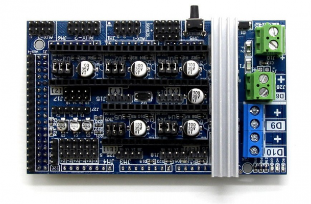
Decided on the controller, drivers an lead screw. An Arduino Mega with Ramps 1.6, this one is equipped with a mosfet heat-sink
Decided to use the T8-2 lead screws this is a trapezoidal 8mm lead screw that has a pitch of 2mm per revolution.
Decides against my spare parts stock T8-8 lead-screw as the weight will allow the carriage to drop when power is turned off.
T8-8 Lead-screw Gravity test
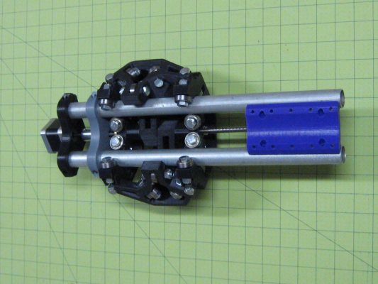
As you can see the carriage has been assembled with a minor setback again needing to order stronger steppers and a new T8-2 Lead-screw.
This by no means will stop me from partially assembling the MPCNC's other components while I wait for the remaining parts to arrive.
Assempled with a temporary 56oz Stepper an T8-8 Lead screw
Computer Programmer / Electronics Technician
|
Re: V1 Engineering's Piper June 06, 2019 09:47PM |
Registered: 6 years ago Posts: 1,863 |
Today received the Arduino controller the Ramps 1.6 with five A4988 drivers modules.
Decided to upload a known Firmware Marlin 1.1.5 to test the the basics, found that I needed a CH34X driver before it would allow an upload.
Marlin 1.1.5 with the controller an Ramps 1.6 an drivers modules boots, however Marlin for MPCNC is going to need some firmware changes as it is displaying garbage.
Will go over it very carefully to see what i missed.
Ok Missed the Full Graphics Boot Screen, works now.
Edited 2 time(s). Last edit at 06/06/2019 10:46PM by Roberts_Clif.
Computer Programmer / Electronics Technician
|
Re: V1 Engineering's Piper June 07, 2019 08:06PM |
Registered: 6 years ago Posts: 1,863 |
Today I received the five steppers, and setup a Ramps controller test, decided to start with a V-Ref of .450
Setup all steppers an preformed simple moves on X, Y, Z, X2 an Y2 drivers functioning at my test current..
Edited 1 time(s). Last edit at 06/07/2019 08:18PM by Roberts_Clif.
Computer Programmer / Electronics Technician
Setup all steppers an preformed simple moves on X, Y, Z, X2 an Y2 drivers functioning at my test current..
Edited 1 time(s). Last edit at 06/07/2019 08:18PM by Roberts_Clif.
Computer Programmer / Electronics Technician
|
Re: V1 Engineering's Piper June 08, 2019 04:09AM |
Admin Registered: 11 years ago Posts: 3,096 |
Quote
Roberts_Clif
Today I received the five steppers, and setup a Ramps controller test, decided to start with a V-Ref of .450
Setup all steppers an preformed simple moves on X, Y, Z, X2 an Y2 drivers functioning at my test current..
A piece of advice; setting vref with a meter only gives you an indication. If you miss steps you should manually raise the vref on the specific stepper and literally feel the heat element with your finger and keep your eye on it to see if it doesn't overheat and go into overheat protection mode.
In my experience vref usually needs to be set a bit higher than the anticipated value.
Here's a good explanation (at the timecode provided):
[youtu.be]
http://www.marinusdebeer.nl/
|
Re: V1 Engineering's Piper June 08, 2019 09:13AM |
Registered: 6 years ago Posts: 1,863 |
Quote
Ohmarinus
A piece of advice; setting vref with a meter only gives you an indication.
Thank you,
I have watched all of his videos an have learned many things. As with many other You-Tubes videos to learn how to repair many broken items.
Was given a Brand New Dead Blu-Ray Player with 200watt Surround sound Had it fixed in minutes, replacing a shorted Cap in the power on circuit with a You-Tube video.
I set the V-Ref to a low value for testing purposes as to make sure that I did not burn up everything on my first ever power on of a Arduino +Ramps 1.6.
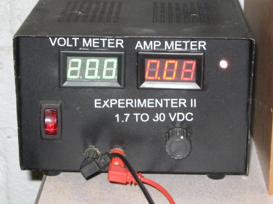
I even use my home made variable 1.7-24 volt DC at 10A Power Supply and slowly turned up the supply voltage watching the current meter.
Using a 10A 12Volt CB radio power supply with a center tapped transformer, I created this simple variable 1.7-24 volt DC at 10A Power Supply for all my electronics testing projects.
After the CB Radio enthusiast dropped these power supplies starting being donated to me by every one who new I was an electronics technician.
Did not use Center tap wanted the Full 24 Vac from transformer
My Designed Schematics for anyone interested.
1-PowerSupply1-30volt10amp.pdf
Edited 4 time(s). Last edit at 06/08/2019 09:19AM by Roberts_Clif.
Computer Programmer / Electronics Technician
|
Re: V1 Engineering's Piper June 08, 2019 09:28AM |
Registered: 6 years ago Posts: 1,007 |
|
Re: V1 Engineering's Piper June 08, 2019 01:29PM |
Registered: 6 years ago Posts: 1,863 |
Quote
MKSA
Considering all these bearings pressing and trying to roll on two galvanized steel tubes (what about their alignment ?), no wonder you need a lot of torque !
From all the videos I have watched of others who have built the V1 Engineering MPCNC before me and or similar like the Piper or LowRider CNC this is not a problem.
After assembling the main carriage I find that the Z-Axis moves smoothly, so smoothly in fact that one could barely tell any differences between the smooth rods in a 3D Printer.
Simply speaking I found that the EMT conduits I have a smooth machined surface lines along their lengths if aligned with the bearing this will allow for a smoother travel.
So if I mark the bearing travels on the conduits an polish the linear surface to allow an even smoother travel should never have any problems.
An Extra Brace is warranted to help the EMT conduit from warping with the weight of the Spindle motors or Larger Engraver motors.
The main reason for the higher torque stepper motors, is when you want to cut wood or aluminum you will find that the stronger steppers will Allow for faster more accurate cutting...
Myself I want to CNC circuits boards, 3D Printer Wood Case Frames and 3D print larger Models might even try a laser, though was told that the LED lasers have a really short lifespan.
Edited 1 time(s). Last edit at 06/08/2019 03:41PM by Roberts_Clif.
Computer Programmer / Electronics Technician
|
Re: V1 Engineering's Piper June 10, 2019 02:52AM |
Registered: 5 years ago Posts: 148 |
That's a nice PSU you're made, you've done a great job Roberts_Clif !
Looking at your circuit diagram (which is very nice by the way), we generally go by a rough rule of thumb in the development department of 2200uf per amp for the smoothing caps and add plenty of HF decoupling/filtering too when designing new PSU's, but that's for high-spec PSU's for industrial and school use etc.
Looking at your circuit diagram (which is very nice by the way), we generally go by a rough rule of thumb in the development department of 2200uf per amp for the smoothing caps and add plenty of HF decoupling/filtering too when designing new PSU's, but that's for high-spec PSU's for industrial and school use etc.
|
Re: V1 Engineering's Piper June 20, 2019 11:53PM |
Registered: 6 years ago Posts: 1,863 |
Quote
Pippy
That's a nice PSU you're made, you've done a great job Roberts_Clif !
Looking at your circuit diagram (which is very nice by the way), we generally go by a rough rule of thumb in the development department of 2200uf per amp for the smoothing caps and add plenty of HF decoupling/filtering too when designing new PSU's, but that's for high-spec PSU's for industrial and school use etc.
Well Thank you.
Have never pushed it to the max while connected to a scope to see the ripple voltage, though knew I needed larger filter capacitors.
I heard the noise on my old CB when I was testing the supply, but did not have the capacitors available at that time.
Will be needing a variable supply more and more with my 3D Printers an will be doing some modification in the future. Testing for low ripple with max currents will be an important test.
I had also labeled the Power as 1.7 - 30 VDC, though it will never reach 30volts, the transformer is only rated for 24 volts center tapped at 10 amps.
Edited 4 time(s). Last edit at 06/21/2019 08:00AM by Roberts_Clif.
Computer Programmer / Electronics Technician
|
Re: V1 Engineering's Piper June 24, 2019 01:08PM |
Registered: 6 years ago Posts: 1,863 |
After assembling the MPCNC wanted to do one more final test before continuing forward.
You will not believe this but the first test out, blew the Adruino's AMS1117-5 regulator.
So ordered the new regulators and of course you can get 10 for the price of one so purchased a lot of 10.
After replacing the regulator tried the test again an every thing worked except the Stepper motors.
Troubleshooting high and low could not do any thing to get them working again.
Did what anyone who wanted the system up and running would do, Ordered the whole shooting match again.
Arduino Mega with Ramps 1.6 and five A4988 stepper motor drivers.
Today I received the new electronics and started to test, an wouldn't you know it the thing will do run.
After more troubleshooting I found a single A4988 stepper motor driver module was shorted out.
Removed the shorted driver and tested as much as possible with only 4 Driver modules.
These boards are working, Now I decided to test the other electronics parts.
And found that all original drivers modules are dead, the shorted one making 6 dead stepper motor modules.
Did determined that the Arduino and Ramps 1.6 survived the AMS1117-5 regulator destruction twice.
Today I ordered ten stepper motor driver modules.
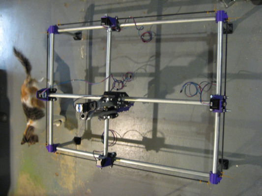
Advancing through the Build level and waiting for more parts, thought I would post a couple photos.
Finally decide on a build size 508 X 762 X 292mm (20inches X 30inches X 11.5 inches)
Need to re-examine the firmware the LCD displays only about half what I believe should be displayed.
Will Start with large sheets of paper to draw a complex sketch using a pencil, would like to see it do something.
Then will draw a set of calibrations drawings or rulers all over the paper.
Need to start thinking about printing some cable chains to get the MPCNC looking professional.
Note:
The driver modules that were used in the firmware build were DRV8825 this has 32steps for the same settings, as the A4988 drivers that were purchased for My MPCNC which have 16 steps.
Do not know if this will make much difference as long as the firmware is changed to accommodate the 16step driver modules.
Edited 1 time(s). Last edit at 06/24/2019 01:09PM by Roberts_Clif.
Computer Programmer / Electronics Technician
|
Re: V1 Engineering's Piper June 24, 2019 01:25PM |
Registered: 11 years ago Posts: 5,780 |
DRV8825s skip microsteps at low speeds.
If you're going for professional results, why do you keep messing with toy electronics? Those failing/failed motor driver modules are trying to tell you something. Get a Smoothieboard or a Duet (not a junky clone from China) and be done with it.
Ultra MegaMax Dominator 3D printer: [drmrehorst.blogspot.com]
|
Re: V1 Engineering's Piper June 24, 2019 03:44PM |
Registered: 6 years ago Posts: 1,863 |
Thank you.
This is why I chose the A4988 Driver modules, I can still add the DVR8825 with the double diode TL smoother if this fails to give clean steps at 1/16.
Quote
the_digital_dentist
If you're going for professional results, why do you keep messing with toy electronics? Those failing/failed motor driver modules are trying to tell you something. Get a Smoothie-board or a Duet (not a junky clone from China) and be done with it.
Actually this is my First Arduino / Ramps 1.6 configuration, and it was my own mistakes that caused the damage not the fault of the controller or the drivers modules...
An the Arduino / Ramps 1.6 configuration are well suited to do this kind of controller functions.
As for the big picture even this is far out of my budget, am extremely lucky. Bet Smoothie or Duet would not reduce the cost for those who cannot afford retail.
So I am very thankful just to have anything in this field of technology, as you so nicely pointed out to me (" junky clone from China ") in my possession.
Thank you China so very much for creating, cloning open source or what ever you did to produce these high quality affordable products for all of us.
(The Big Bang Theory Quote)
"you know for a group of guys who claim to have spent most of there lives being bullied you can be real jerks!"
[www.youtube.com]
Edited 2 time(s). Last edit at 06/26/2019 09:27AM by Roberts_Clif.
Computer Programmer / Electronics Technician
|
Re: V1 Engineering's Piper June 24, 2019 04:49PM |
Registered: 6 years ago Posts: 1,863 |
So lets convert my MPCNC hardware with the firmware
#define DEFAULT_AXIS_STEPS_PER_UNIT { 200, 200, 800, 200 }
To calculate I use the Prusa Calculator
First with the Belt driven axis
From
1.8° (200 per revolution) 1/32 μStep Belt Pitch 2mm Pulley tooth count = 200
To
1.8° (200 per revolution) 1/16 μStep Belt Pitch 2mm Pulley tooth count = 100
Second with the Lead Screw driven axis
From
1.8° (200 per revolution) 1/32 μStep Belt Pitch 8mm Lead-screw Pitch = 800
To
1.8° (200 per revolution) 1/16 μStep Belt Pitch 2mm Lead-screw Pitch = 1600
#define DEFAULT_AXIS_STEPS_PER_UNIT { 100, 100, 1600, 100 }
Computer Programmer / Electronics Technician
|
Re: V1 Engineering's Piper June 24, 2019 06:14PM |
Registered: 9 years ago Posts: 204 |
Thanks for the pictures, Your making good progress. This thread sparked my interest into building one too. Parts are on order & 20 hours worth of prints done.
a couple of questions if you don't mind.........
Are you going to use end stops and implement the auto squaring function?
What software are you going to use to make the G-code?
a couple of questions if you don't mind.........
Are you going to use end stops and implement the auto squaring function?
What software are you going to use to make the G-code?
|
Re: V1 Engineering's Piper June 24, 2019 07:42PM |
Registered: 6 years ago Posts: 1,863 |
Quote
Shank man
Are you going to use end stops and implement the auto squaring function?
Not at this time, will need to learn before I start working with auto squaring function.
In fact when I did my first test I accidental grabbed the Z Stepper motor cable and connected it to Y2 (E1) and the Z-Axis moved smoothly across and back.
Only noticed when out of the corner of my eye an thought I saw the Z-Axis turning then tried again and knew I had hooked up the Z-Stepper motor incorrectly to Y2 (E1).
Then connected the correct Stepper motor and tried again and visually saw no differences in the Y axis movement. I know it had probably lagged a little though moved smoothly.
Quote
Shank man
What software are you going to use to make the G-code?
I will be testing all software I can find starting with Estlcam V11. If you have any thoughts and a demo download or free software post will try and find the ones I like best...
I was hoping to test the controller using a pen or pencil on paper to see how the stock Marlin firmware works, at first with simple one layer drawings.
Then graduate to more complex sketches.
found this picture some time ago and hand traced it with CorelDraw.
Edited 4 time(s). Last edit at 06/24/2019 08:59PM by Roberts_Clif.
Computer Programmer / Electronics Technician
|
Re: V1 Engineering's Piper June 25, 2019 12:25PM |
Registered: 6 years ago Posts: 1,863 |
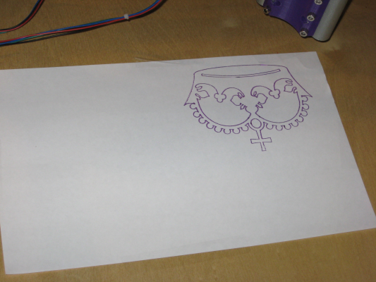
1st Test Print a simple Crown, by George it works.
Have not 3D Printed any holders yet so I duct taped a purple Sharpe to the Tool holder, this was for just a quick test.
Tried to turn Sena1 into a G-Code. Followed all the instructions still, Have not yet figured out how to create my G-code so I used the Crown on [www.v1engineering.com]
It is a little weak on the steppers V-Ref though for testing I will not worry about this until after I 3D Print a power supply case designed for it. Thinking about designing a case for the Controller and Ramps 1.6 on the back of the tool carriage, routing the cables via a series of cable chains, then will only have the power supply wires to route from the rear of the main floor to the controllers.
Will have to think about how to gain another stepper motor driver to run an extruder maybe.
[www.reprap.me]
Edited 2 time(s). Last edit at 06/25/2019 09:06PM by Roberts_Clif.
Computer Programmer / Electronics Technician
|
Re: V1 Engineering's Piper June 26, 2019 06:37AM |
Registered: 9 years ago Posts: 204 |
|
Re: V1 Engineering's Piper June 26, 2019 07:18AM |
Admin Registered: 11 years ago Posts: 3,096 |
Quote
Shank man
Have you decided on a spindle yet? Will it be switched on/off through the software? I was thinking of powering a relay through the fan connector on the RAMPS board to control the power to the spindle motor. What do you think?
I'm not sure of that's a good idea. Would you be able to use PWM for the spindle speed that way?
http://www.marinusdebeer.nl/
|
Re: V1 Engineering's Piper June 26, 2019 09:48AM |
Registered: 6 years ago Posts: 1,863 |
Quote
Shank man
Have you decided on a spindle yet? Will it be switched on/off through the software? I was thinking of powering a relay through the fan connector on the RAMPS board to control the power to the spindle motor. What do you think?
I have not completely decided on the spindle, suggestions may help.
again have not decided on the mode of operation an any suggestions may help.
Quote
Ohmarinus
I'm not sure of that's a good idea. Would you be able to use PWM for the spindle speed that way?
Use a Ac Programmable Dimmer Module for Arduino
Or
Use a DeWalt DW660 or a 750W Variable Speed Grinding Rotary Tool.
The main consideration is what kind if bits can you get, because without a good selection of bits you have nothing.
any suggestions will be helpful.
Edited 2 time(s). Last edit at 06/26/2019 09:50AM by Roberts_Clif.
Computer Programmer / Electronics Technician
|
Re: V1 Engineering's Piper June 26, 2019 12:40PM |
Registered: 9 years ago Posts: 204 |
Quote
Ohmarinus
Quote
Shank man
Have you decided on a spindle yet? Will it be switched on/off through the software? I was thinking of powering a relay through the fan connector on the RAMPS board to control the power to the spindle motor. What do you think?
I'm not sure of that's a good idea. Would you be able to use PWM for the spindle speed that way?
I was thinking more along the lines of using it to just switch a relay on and off. The spindle would get its power through the relay contacts. Similar to powering a Heat bed through a relay. Or I could just use a toggle switch and manually switch it. I was going to get a 120 volt AC spindle.
|
Re: V1 Engineering's Piper June 26, 2019 02:02PM |
Registered: 6 years ago Posts: 1,863 |
oh!
I see no reason why the can not use a simple relay to switch the power on and off for a Rotatory tool.
There are many E-Bay Arduino Relays / Solid State Relays available for any power requirements.
Edited 2 time(s). Last edit at 06/26/2019 02:03PM by Roberts_Clif.
Computer Programmer / Electronics Technician
|
Re: V1 Engineering's Piper June 27, 2019 06:12PM |
Registered: 6 years ago Posts: 1,863 |
Today I decide to test test main floor platform for level.
With ~6mm above the bed then lowered the Tool plate 6mm on all four corners an dead center the platform.
Being really close to the main floor platform here, took my filler gauges out and began measuring the height.
After comparing all five locations, deturmined that the MPCNC that I just built is measuring 0.06mm from level.
Knew I was being careful making my EMT Conduit cuts, but never ever expected that I was being this precise.
This is going to be is enough to mount a Large Aluminum Plate above the floor Platform, heated or not heated.
For 3D Printing large 508 X 762 X 292mm Models WoW! this is going to take a long, long, long, time to print.
A simple Benchy 4X size will take1 day with .4mm nozzle with a 1mm nozzle prints will take 5 1/2 hours.
This may be doable.
Computer Programmer / Electronics Technician
|
Re: V1 Engineering's Piper June 29, 2019 06:55PM |
Registered: 6 years ago Posts: 1,863 |
Today my DC-DC Step Down Buck Converter 1.5V 3V 5V 9V 12V and Adjustable at 3 amps came in.
I am now powering my ramps with a 20amp 24volt power supply.
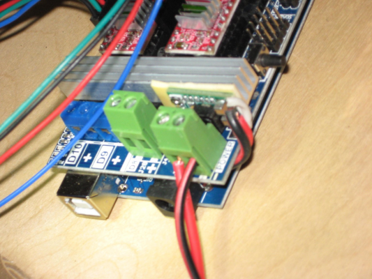
I removed D1 replacing it with the output of the buck converter I soldered the diode anode side to IN (24vdc) and soldered the
diode cathode side to VO leaving the GND terminal to be soldered to the Ramps ground Power Connector.
I did not install a DC-DC Step Down Buck Converter Module set to 5volts to replace the AMS1117-5.0 at this time
This was on my agenda so I could use the full graphics controller that draws to much current from the AMS1117-5.0.
Will do this after the Full graphics controller arrives.
Edited 3 time(s). Last edit at 06/29/2019 06:57PM by Roberts_Clif.
Computer Programmer / Electronics Technician
|
Re: V1 Engineering's Piper July 02, 2019 01:08PM |
Registered: 6 years ago Posts: 1,863 |
Today I duplicated my DC-DC Step Down Buck Converter to my Spare Ramps 1.6 board. I am now powering both ramps with 24volt power supplies.
Have not ordered a pair of Full Graphics controllers for my newly purchased Arduino Mega 2560 R3's and Ramps.
Though it is still on my list of parts to be ordered.
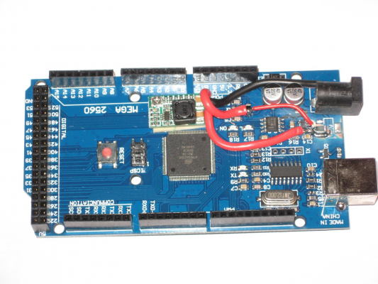
My next modification will be to remove the AMS1117-5.0 regulator on the Arduino and replace it with this same DC-DC Step Down Buck Converter. This time instead of setting it to a variable voltage will be using the set 5 volt jumper pin on the converter.
This will allow for the additional power requirements needed to operate the Full Graphics controller I will be using. All power supplied from a single 24vdc power source from the Ramps 1.6 controller power pins...
Computer Programmer / Electronics Technician
|
Re: V1 Engineering's Piper July 03, 2019 12:21PM |
Registered: 6 years ago Posts: 1,863 |
Today I believe I have the Estlcam figured out I printed a more complex sketch.
I went off the paper on the feet
After printing this sketch I believe I am ready to setup a extra Stepper motor Driver for my Ramps 1.6 for the extruder.
Will be looking a this Stepper motor Expander
Has any one ever tried these Stepper motor expanders
Edited 2 time(s). Last edit at 07/03/2019 05:17PM by Roberts_Clif.
Computer Programmer / Electronics Technician
|
Re: V1 Engineering's Piper July 08, 2019 11:19AM |
Registered: 6 years ago Posts: 1,863 |
Today I was wiring end-stop switches using this video on my Arduino Mega 2560 R3 an Ramps 1.6 making sure the wire were exactly the same as the video.
Well I blew the AMS1117-05 in a heartbeat so today I replace the AMS1117-05 with a DC-DC Step Down Buck Converter 1.5V 3V 5V 9V 12V 3A Adjustable Module this was set to the 5V jumper.
My question is why did this switch made by BigTree-Tech.com for maker bot kill the AMS1117-05, tested the switch it operated correctly.
My 2nd question is now that Arduino has a 3amp 5volt supply should be able to run a LCD 12864 Smart Controller correct.
I must be right at the max current limit for the regulator because when I power it on with the new regulator is now works correctly.
Edited 5 time(s). Last edit at 07/08/2019 02:27PM by Roberts_Clif.
Computer Programmer / Electronics Technician
|
Re: V1 Engineering's Piper July 08, 2019 05:07PM |
Registered: 7 years ago Posts: 619 |
Quote
Roberts_Clif
I have noted a distinctive difference between the SD card Print and the OctoLapse Print textures.
Noted: in the Photos above the model on right was printed with the SD Card While Model on the left within OctoPrint's Octolapse.
You will note a distinct texture difference. Will print another model using same ABS filament with SD card to verify if smoothness returns.
I have been hanging out on the Octoprint lists for a while after I ran into some problems and it has been discovered that for a while Octoprint serial port I/O to printer controllers has been causing print quality issues. Many experiments have been run that show SD card prints to be of higher quality than serial port Octoprints. Some kind of serial port latency and/or throughput bottlenecks are causing print stalling and jerkiness that result in in less-than-perfect surface quality on print jobs.
So, it may be that the time-lapse is contributing to the surface quality degradation, but it probably isn't all of it...
Pity, I really like Octoprint. I will be trying a Duet Maestro on my main printer next (someone had a sale
 . I am hoping to be able to print directly to a Duet from Simplify3D and CURA.
DLC
Kits: Folgertech Kossel 2020 upgraded E3Dv6, Anet A8 upgraded E3Dv6, Tevo Tarantula enhanced parts and dual-head, TronXY X5SA Pro(E3DHemera).
Scratch: Large bed Cartesian, exchangeable heads, Linear slide Delta, Maker-Beam XL Micro Delta, 220x220CoreXY.
Sorry, only registered users may post in this forum.
