MPCNC
Posted by Shank man
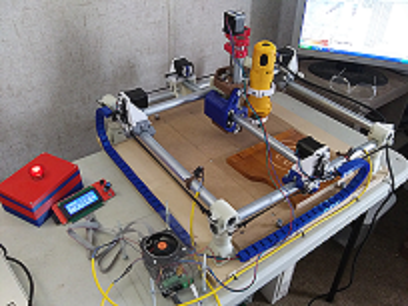
I went with the more compact 24" x 24" version. This thing is going to need a dedicated spot and I haven't quite figured
out where I'm going to keep it.
There is quite a bit of printing involved with making all of the parts. Including
the cable chain and Dewalt tool holder it has
to be close to 170 hours of print time. I broke up the workload amongst 3
printers. I'd rather have a printer doing a 6 hour print
than just one printer printing for 18 hours. This also
accounted for the variety of filament colors. I like to make it a point
to be consistent with the colors but I had around
7 old partial spools of different colors and types to use up. The
motor mounts and DeWalt cut off tool holder were done in ABS and the
rest is PLA & PLA+. The red Burly parts are PETG.
I made every effort to buy as many parts as I could
from a local DIY store. Conduit wasn't a problem
but the selection of hardware was severely limited.
5/16 Nylocks nuts are sold in packages of 15, Bolts are sold
individually. There were no 5/16, 1-1/4" bolts so I had to cut down some
1-1/2" ones. All 28 of them. There is nothing I enjoy more than cutting
down bolts. Being a low grade course threaded bolt made this
somewhat easier.
I'm using a Sainsmart RAMPS 1.4 shield with a Arduino 2560.
The 72oz motors are hooked up to DRV8825's set in 1/16 step mode
I added a Smart Controller in order to engrave directly from a SD card.
I couldn't get the pre-configured V1 Engineering Marlin 2.0 firmware to
compile so I reverted back to a older version that I'm using for my printer. I
used Slic3r generated G-code to check all the movements and to plot a
picture. I had to edit out the G28 home all axis command since I don't have any end
stops hooked up yet. The MPCNC design doesn't call out for end stops. I'm
guessing that wherever you park the tool is the origin
Prusa I2
Gen7-ARM 2.0 / Teacup
Genuine J-Head Mk V-BV
Hypercube
RAMPS 1.4 / Marlin
E3D V6
Piper 1 Version 2
Gen7-ARM 2.0 / Teacup
E3D V6
MPCNC
RAMPS 1.4/ Marlin
When I placed my order for the Dewalt cut out tool I also ordered some 1/8"
end mills and V-bits. The package arrived but there were no contents in the
V-bit container. Either it was sent out from the manufacturer empty or
someone working at Amazon took them. I'm a little disappointed because I
was looking forward to engraving some text. At least I have the end mills to
work with.
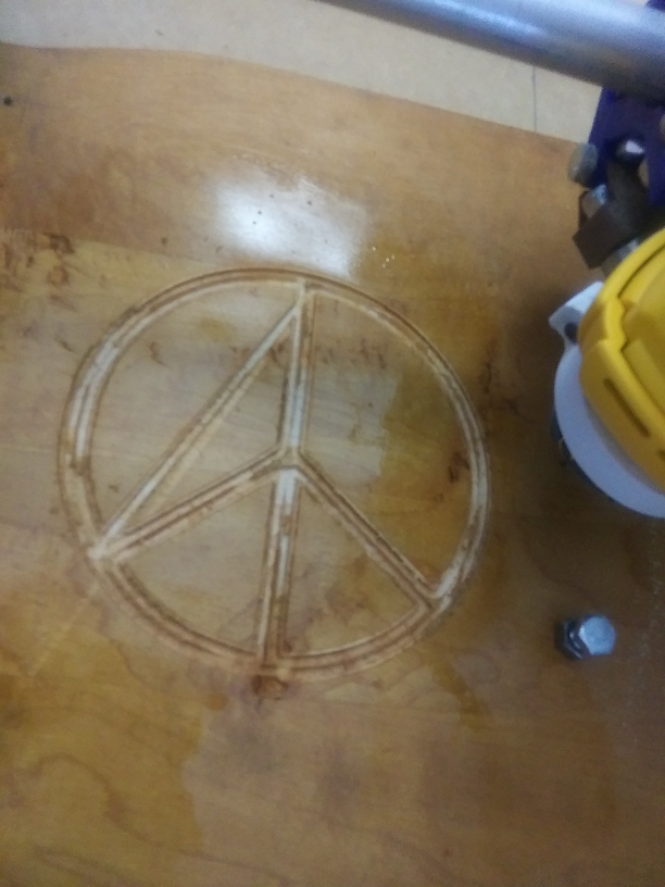
I managed to engrave this 2 mm deep Peace symbol with some Slic3r
generated gcode without breaking any bits. I scavenged the wood from
some old furniture. I think its pine but I'm not sure. The Z hop was set at -7
which reduced most of the travel lines but I couldn't eliminate all of them.
The layer height (cutting depth) was set at 0.2mm with a feed rate of 60mm
per second. Both are very conservative values and the cut out tool
had no trouble at all with keeping up. I'll move on to Estlcam to generate
gcode for any further engravings.
I'm going to switch over the firmware from Marlin to something else.
I've heard of Marlin for CNC but I didn't see where
the V1 Engineering copy was any different from regular 3D printing firmware.
The only difference I could see was that there was a V1 splash screen setup. Is
there any CNC firmware for the RAMPS 1.4? I'm going to look into a GRBL
shield.
This thing really kicks up the dust so a vacuum hose attachment will be
the next thing I'll print. The Dewalt tool holder from Thingiverse works
exceptionally well and is a great design.
One other problem I'm contending with is due to the weight of the
Dewalt, the 4 start ACME screw won't hold it in place and it drops down
onto the engraving surface when there is no power to the Z motor.
end mills and V-bits. The package arrived but there were no contents in the
V-bit container. Either it was sent out from the manufacturer empty or
someone working at Amazon took them. I'm a little disappointed because I
was looking forward to engraving some text. At least I have the end mills to
work with.
I managed to engrave this 2 mm deep Peace symbol with some Slic3r
generated gcode without breaking any bits. I scavenged the wood from
some old furniture. I think its pine but I'm not sure. The Z hop was set at -7
which reduced most of the travel lines but I couldn't eliminate all of them.
The layer height (cutting depth) was set at 0.2mm with a feed rate of 60mm
per second. Both are very conservative values and the cut out tool
had no trouble at all with keeping up. I'll move on to Estlcam to generate
gcode for any further engravings.
I'm going to switch over the firmware from Marlin to something else.
I've heard of Marlin for CNC but I didn't see where
the V1 Engineering copy was any different from regular 3D printing firmware.
The only difference I could see was that there was a V1 splash screen setup. Is
there any CNC firmware for the RAMPS 1.4? I'm going to look into a GRBL
shield.
This thing really kicks up the dust so a vacuum hose attachment will be
the next thing I'll print. The Dewalt tool holder from Thingiverse works
exceptionally well and is a great design.
One other problem I'm contending with is due to the weight of the
Dewalt, the 4 start ACME screw won't hold it in place and it drops down
onto the engraving surface when there is no power to the Z motor.
|
Re: MPCNC July 21, 2019 12:46PM |
Registered: 6 years ago Posts: 1,863 |
Quote
Shank man
Local store.
Conduit wasn't a problem but the selection of hardware was severely limited.
5/16 Nylocks nuts are sold in packages of 15, Bolts are sold individually. There were no 5/16, 1-1/4" bolts so I had to cut down some 1-1/2" ones. All 28 of them. There is nothing I enjoy more than cutting
down bolts. Being a low grade course threaded bolt made this somewhat easier.
I split my 3D Prints up with my two 3D Printers
Like you purchased the 5/16 1-1/2 bolts I cut them close using a hacksaw the using a grinder to smooth the end an allow the Nylock nuts to thread on.
If I had it to do over I would have used my bolt cutters then grinded the end smooth to allow the Nylock nuts too thread on.
The bolt heads were also to large and needed to have a little trimmed off on two bolts.
I see you are using Slic3r to do some testing, what did you use to generate the Peace sign G-Code.
I have been fumbling with learning to operate EstlCam through the minute delays before it will allow loading saved projects or slicing any G-Code for any project you are currently working on.
Have not actually cut anything Still procrastinating my final printing accessories Power Supply mounting, Ramps and LCD cases ect, though I made EstlCam G-Code for the MPCNC sketch Sena.
I have been looking at this Wirelessly Control a CNC from a Web Interface to finalize the MPCNC Electronics.
Edited 1 time(s). Last edit at 07/21/2019 12:53PM by Roberts_Clif.
Computer Programmer / Electronics Technician
Quote
Roberts_Clif
[ I see you are using Slic3r to do some testing, what did you use to generate the Peace sign G-Code.
I have been fumbling with learning to operate EstlCam through the minute delays before it will allow loading saved projects or slicing any G-Code for any project you are currently working on.
Have not actually cut anything Still procrastinating my final printing accessories Power Supply mounting, Ramps and LCD cases ect, though I made EstlCam G-Code for the MPCNC sketch Sena.
Yeah, I'm still fumbling my way through EstlCam too. I just pulled the peace sign from Google images and ran it through to Inkscape to create a SVG. I imported the SVG into Blender to make
a STL. which I bring into Slic3r. Not the ideal to create a tool path for a CNC. I was anxious to get started and didn't want to wait until I learned EstlCam.
|
Re: MPCNC July 22, 2019 08:11AM |
Registered: 6 years ago Posts: 1,863 |
Estlcam is not to hard to setup. after loading Click Setup select basic Settings and select Marlin.
Then Click Setup again select CNC Programs select presets Marlin. Length unit millimeter, Feed unit Millimeter per minute, and File Extension g-code.
Then I setup the bits I bought on E-Bay 0.8-3.175mm, attached tools settings.
My attempt of setting Bit tools, Will get larger bit as I need them is attached.
Here is a You-tuber has has a lot of good MPCNC information in many videos.
[www.youtube.com]
However if you want to learn quickly watch this
[www.youtube.com]
Edited 6 time(s). Last edit at 07/22/2019 09:36AM by Roberts_Clif.
Computer Programmer / Electronics Technician
Duet WiFi and Duet Ethernet are other popular options as the controller for MPCNC. See [forum.duet3d.com] for some posts about this. The TMC2660 stepper drivers can handle more current than stepstick-drivers can, making them suitable to drive Nema 23 motors if the motors are chosen carefully.
Edited 2 time(s). Last edit at 07/22/2019 01:04PM by dc42.
Large delta printer [miscsolutions.wordpress.com], E3D tool changer, Robotdigg SCARA printer, Crane Quad and Ormerod
Disclosure: I design Duet electronics and work on RepRapFirmware, [duet3d.com].
Edited 2 time(s). Last edit at 07/22/2019 01:04PM by dc42.
Large delta printer [miscsolutions.wordpress.com], E3D tool changer, Robotdigg SCARA printer, Crane Quad and Ormerod
Disclosure: I design Duet electronics and work on RepRapFirmware, [duet3d.com].
|
Re: MPCNC July 22, 2019 08:03PM |
Registered: 6 years ago Posts: 1,863 |
Quote
dc42
Duet WiFi and Duet Ethernet are other popular options as the controller for MPCNC. See [forum.duet3d.com] for some posts about this. The TMC2660 stepper drivers can handle more current than stepstick-drivers can, making them suitable to drive Nema 23 motors if the motors are chosen carefully.
Thank You
Though from the 32 bit perspective, the Duet design was intended for 3D printing, an a 32 bit controller seems like quite a overkill for a simple CNC
I have the Marlin 2.0 Firmware working perfect on my MPCNC if you need any help with it.Quote
Shank man
I couldn't get the pre-configured V1 Engineering Marlin 2.0 firmware to
compile so I reverted back to a older version
I'm going to switch over the firmware from Marlin to something else.
I've heard of Marlin for CNC
Or
Here Download GRBL for RAMPS GBRL
They Talk about is here in this Thread.
[www.v1engineering.com]
Edited 3 time(s). Last edit at 07/22/2019 08:14PM by Roberts_Clif.
Computer Programmer / Electronics Technician
... no "overkill"! -- if you look at microstepping and lookahead, the ArduinoDue should/could be much faster, to get better/faster/more accurate positioning 
Viktor
--------
Aufruf zum Projekt "Müll-freie Meere" - [reprap.org] -- Deutsche Facebook-Gruppe - [www.facebook.com]
Call for the project "garbage-free seas" - [reprap.org]
Viktor
--------
Aufruf zum Projekt "Müll-freie Meere" - [reprap.org] -- Deutsche Facebook-Gruppe - [www.facebook.com]
Call for the project "garbage-free seas" - [reprap.org]
[/quote]
I have the Marlin 2.0 Firmware working perfect on my MPCNC if you need any help with it.
/[/quote]
Thanks I'll give it another try and post my error messages. Could you post your configuration? When I tried to compile it threw up a error message about not being able to recognize the 2560 board.
Also are you using end stops for homing? It seems odd that they aren't a integral part of the design other than for the auto squaring function. I have some on order along with more engraving bits.
I have no qualms about using a Due or Duet. I'm using the RAMPS because I already had it. This little CNC is showing a lot of promise so I might spend some more on upgrades. This is all new stuff to me so I m going through a big learning curve
|
Re: MPCNC July 23, 2019 07:47AM |
Registered: 6 years ago Posts: 1,863 |
I will do you one better, here is a sharable link to my Marlin 2.0 MPCNC firmware
Just a reminder That Marlin 2.0 requires a Arduino IDE 1.8.8 or newer or PlatformIO to compile.
I have not started using the MPCNC as of this date, I have used the Pen ability an have cut a pocket in a piece of wood. I have test cut many 2D G-Codes getting ready, but it is still in the build process.
I have cables everywhere that need to be in cable chains and the power supply, controller that need to be in a case. Still waiting for time to 3D Print parts and ordered parts to arrive.
Computer Programmer / Electronics Technician
Quote
Roberts_Clif
I will do you one better, here is a sharable link to my Marlin 2.0 MPCNC firmware
Just a reminder That Marlin 2.0 requires a Arduino IDE 1.8.8 or newer or PlatformIO to compile.
.
Thank you, It compiled. Now I have the right firmware to work with
I added some cable chain to run the motor wires and limit switches for homing
the X & Y. I don't think a MPCNC this small really needs auto squaring. The Z
home is set by eye from job to job because of the differences in the
thickness of the wood I've been using. A added lighted E-stop button cuts
power to the Dewalt and the 12 volt power supply in the case of a
emergency. And there have been emergencies!
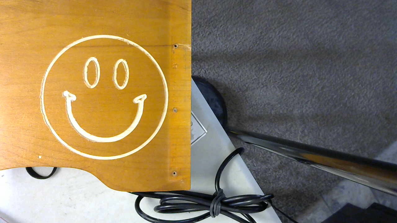
After working through a multitude of setbacks I managed
to engrave this smiley face with a 1/8" end mill.
For now I find it best to stick to simple line drawings with little detail.
They are easier to convert to DXF files. Estelcam will take STL files
but they produce a less then efficient tool path and make for longer
engraving times. My DXF files are created in Inkscape from drawings taken
from Google Images.
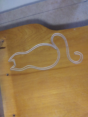
The cat profile was done with a 1/8" V-bit. It produced a nice crisp cut at a
1mm depth
Edited 1 time(s). Last edit at 07/28/2019 04:51PM by Shank man.
the X & Y. I don't think a MPCNC this small really needs auto squaring. The Z
home is set by eye from job to job because of the differences in the
thickness of the wood I've been using. A added lighted E-stop button cuts
power to the Dewalt and the 12 volt power supply in the case of a
emergency. And there have been emergencies!
After working through a multitude of setbacks I managed
to engrave this smiley face with a 1/8" end mill.
For now I find it best to stick to simple line drawings with little detail.
They are easier to convert to DXF files. Estelcam will take STL files
but they produce a less then efficient tool path and make for longer
engraving times. My DXF files are created in Inkscape from drawings taken
from Google Images.
The cat profile was done with a 1/8" V-bit. It produced a nice crisp cut at a
1mm depth
Edited 1 time(s). Last edit at 07/28/2019 04:51PM by Shank man.
|
Re: MPCNC July 28, 2019 05:38PM |
Registered: 6 years ago Posts: 1,863 |
Thank you Shank man for Posting your progress.
I am still looking for a Control case, the one I found and 3D Printed is in fact a horrible 3D Printing Control case, it is so thin you can virtually see thew it.
And I do do want to waste my time with such a horribly Thin Control case, in fact do not believe it would survive very long and not protect the controller.
I have found some Anwenk 1/4"-20 x 15mm Furniture Screw in Nut Threaded Wood Inserts and have install an placed 32 of the them in the CNC main Deck.
Now I can fasten anything with a simple clamp that is 3D Printed or CNC milled using many type of material. First I still want to Find a Controller Case.
One NOTE: Because I decided to make my MPCNC so tall, the power cable on the Dewalt must be carefully positioned or it will cause the Z-Axis too bind on the X or Y max borders.
I decided, I need to get My MPCNC running. So for a quick fix I am going to quickly 3D Print this.
There is a few modification that I believe should be made while the good parts print, I can modify the pieces that want changes on.
[www.thingiverse.com]
Edited 9 time(s). Last edit at 07/28/2019 07:33PM by Roberts_Clif.
Computer Programmer / Electronics Technician
I am still looking for a Control case, the one I found and 3D Printed is in fact a horrible 3D Printing Control case, it is so thin you can virtually see thew it.
And I do do want to waste my time with such a horribly Thin Control case, in fact do not believe it would survive very long and not protect the controller.
I have found some Anwenk 1/4"-20 x 15mm Furniture Screw in Nut Threaded Wood Inserts and have install an placed 32 of the them in the CNC main Deck.

Now I can fasten anything with a simple clamp that is 3D Printed or CNC milled using many type of material. First I still want to Find a Controller Case.
One NOTE: Because I decided to make my MPCNC so tall, the power cable on the Dewalt must be carefully positioned or it will cause the Z-Axis too bind on the X or Y max borders.
I decided, I need to get My MPCNC running. So for a quick fix I am going to quickly 3D Print this.
There is a few modification that I believe should be made while the good parts print, I can modify the pieces that want changes on.
[www.thingiverse.com]
Edited 9 time(s). Last edit at 07/28/2019 07:33PM by Roberts_Clif.
Computer Programmer / Electronics Technician
Quote
Roberts_Clif
Thank you Shank man for Posting your progress.
I am still looking for a Control case, the one I found and 3D Printed is in fact a horrible 3D Printing Control case, it is so thin you can virtually see thew it.
And I do do want to waste my time with such a horribly Thin Control case, in fact do not believe it would survive very long and not protect the controller.
I have found some Anwenk 1/4"-20 x 15mm Furniture Screw in Nut Threaded Wood Inserts and have install an placed 32 of the them in the CNC main Deck.
[attachment 112315 MyMPCNC-1.jpg]
Now I can fasten anything with a simple clamp that is 3D Printed or CNC milled using many type of material. First I still want to Find a Controller Case.
One NOTE: Because I decided to make my MPCNC so tall, the power cable on the Dewalt must be carefully positioned or it will cause the Z-Axis too bind on the X or Y max borders.
I decided, I need to get My MPCNC running. So for a quick fix I am going to quickly 3D Print this.
There is a few modification that I believe should be made while the good parts print, I can modify the pieces that want changes on.
[www.thingiverse.com]
Thanks again for letting me download your Marlin configuration. It was a tremendous help. Your MPCNC is looking good. I need to rethink using a controller case. My current setup has it too close
to the MPCNC and the cooling fan is sucking in a lot of sawdust. So far I've only done a few very small engravings and they created a lot of chips. The fine dust particles get blown around by
the cutoff tool fan. I'm also using t-nuts to hold down the work piece. These are a must. I still need to print a vacuum hose adapter, mount the CNC to a sturdy table and figure out how to
make some decent DXF files to engrave.
Edited 1 time(s). Last edit at 07/29/2019 05:44AM by Ohmarinus.
|
Re: MPCNC July 29, 2019 09:44AM |
Registered: 6 years ago Posts: 1,863 |
I am not sure it appears that you are using a Dewalt DW660
Though there are many Vacuum duct for The Dewalt Dw660 I decided on the one below, it appears to be the simplest to allow for replacement if Router bits.
[www.thingiverse.com]
Edited 1 time(s). Last edit at 07/29/2019 09:46AM by Roberts_Clif.
Computer Programmer / Electronics Technician
Though there are many Vacuum duct for The Dewalt Dw660 I decided on the one below, it appears to be the simplest to allow for replacement if Router bits.
[www.thingiverse.com]
Edited 1 time(s). Last edit at 07/29/2019 09:46AM by Roberts_Clif.
Computer Programmer / Electronics Technician
The work pieces are held in place with 5/16 bolts screwed into
T-nuts embedded in the spoil board. Using 5/16 bolts is a bit overkill but it
eliminates any chance of the work piece moving around when the engraving
starts. I put spacers between the work piece and the spoil board when I'm
doing cuts. This keeps damage to the spoil board at a minimum when the
cutting bit reaches the end.
My ellipses are coming out a bit choppy. I'm thinking of adding
another jumper underneath the driver to increase the step mode to
1/32. I'm currently using DRV8825's in 1/16 step mode. I'm hoping that by
increasing the step count it will improve the resolution of any cuts with
curves.
|
Re: MPCNC August 04, 2019 10:16PM |
Registered: 6 years ago Posts: 1,863 |
I got my Controller Case Printed and partially installed, an working on installing the Cable chains and cable chain trays.
Changed the front Display cover to Read "MY MPCNC" attached STL file for all to use in wanted.
MyMPCNC_-_ElectronicBox_LCD.stl
Thought seriously about mounting the controller above the Z-Stepper motor, extending the Z-Axis conduits an a modified Z_Lower_C_Burly to allow attaching the V3.0 Scalar electronics Box.
Might be less dust above the Stepper motor on the Z-Axis, It is not like any of the axis on the MPCNC are going to move really fast in any direction.
Ordered longer Stepper motor Cables
Getting ready for the completion I have many test models already to cut, mill carve, ect... from wood to aluminum from simple too complex waves and images.
Need to learn more about my Auto-Desk Fusion 360 CNC features, have been using the 3D modeling.
Knew I had more learning to Do with Fusion 360 Free for hobbyist. Time to get back to YouTube and start learning fast.
Edited 1 time(s). Last edit at 08/04/2019 10:26PM by Roberts_Clif.
Computer Programmer / Electronics Technician
|
Re: MPCNC August 08, 2019 05:53PM |
Registered: 6 years ago Posts: 1,863 |
Hello again;;
I discovered today that the longer Stepper motor cables I purchased from California.
Are in fact being shipped from mainland china, so it will be quite some time before I see the parts if ever.
How is it that E-Bay continues allow this to happen, as many times as we have all complained this should have stop.
May have to buy spares from somewhere else to be able to finish the MPCNC build.
Edited 1 time(s). Last edit at 08/08/2019 05:54PM by Roberts_Clif.
Computer Programmer / Electronics Technician
Quote
Roberts_Clif
Hello again;;
I discovered today that the longer Stepper motor cables I purchased from California.
Are in fact being shipped from mainland china, so it will be quite some time before I see the parts if ever.
How is it that E-Bay continues allow this to happen, as many times as we have all complained this should have stop.
May have to buy spares from somewhere else to be able to finish the MPCNC build.
Stepper motors never seem to come with long enough wires.
I bought 100 feet of bulk cable a few years ago. This way I can custom cut the lengths to only what is needed for these kind of projects.
I found that 22 AWG stranded sensor type cable works well to power the motors. The more
strands the greater the flexibility that means a longer cable life span. It's cheap when bought
in bulk and can also be used for end stops,fans & lights. For a little extra cost, a shielded version or Plenum
type can be had. Plus it already comes pre-twisted and jacketed to make wire management a bit
easier. PUR jacket types are more flexible than the PVC.
[www.automationdirect.com]
Reading though the comments posted on the V1 Engineering site, It was said that 90% of MPCNC builders don't want end stops. By positioning
the router tip and entering a G92 X0 Y0 Z0 code is all that is needed to establish a home position.
My biggest problem so far has been with switching out the tool bit when a tool change is called for. I can't get my big fat over caffeinated fumble fingers in place to activate the chuck lock
to loosen the chuck and get the bit out. When I do manage to get it out I can't apply enough twisting force to tighten in the replacement enough to make sure
it doesn't come out when engraving. That' happened twice. In order to swap out the bits, I remove the Z axis to change it out.
This is where having the end stops has helped me, I use them to home the CNC after changing out the bit to begin the next cut.
I've been editing the G-code to make one CNC program into two on account of having to change out the bits this way.
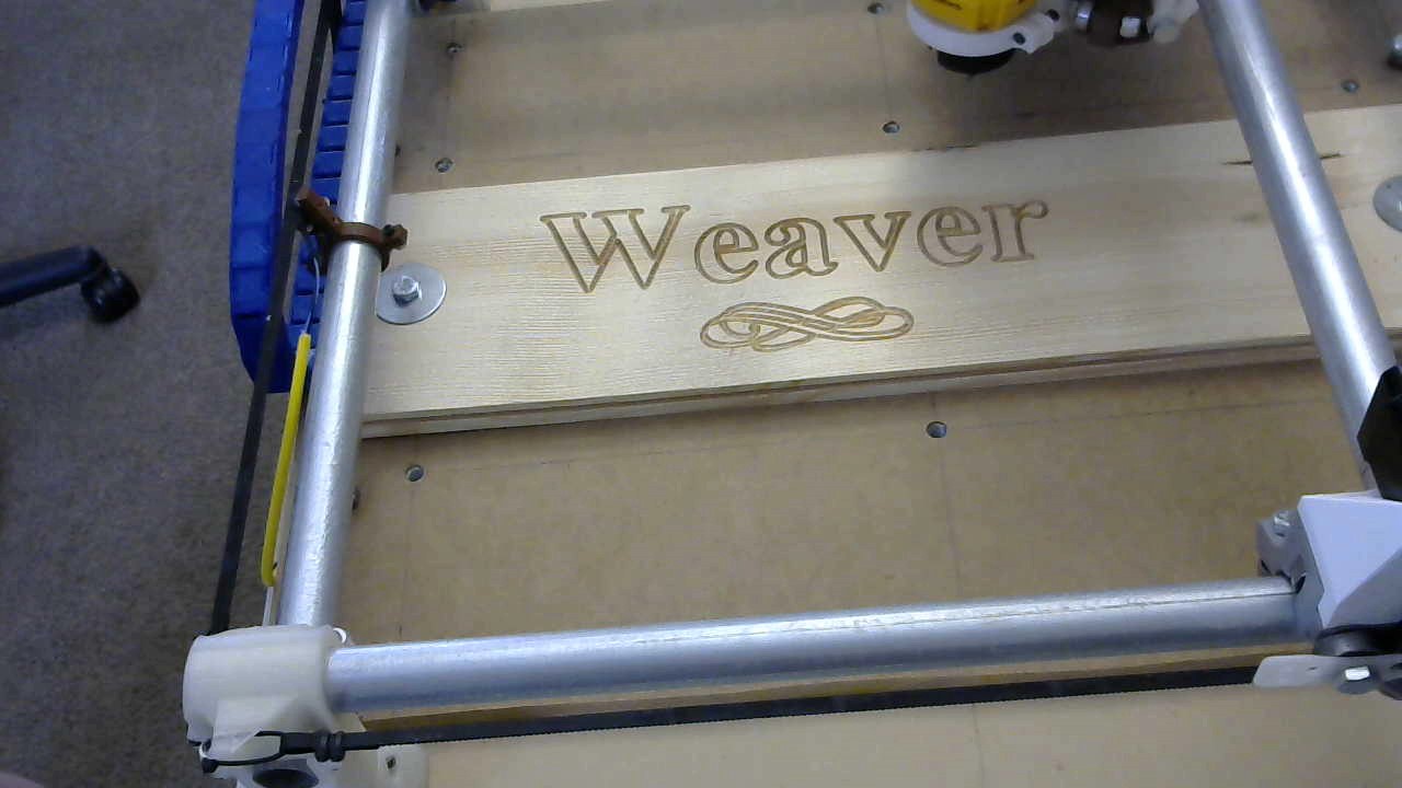
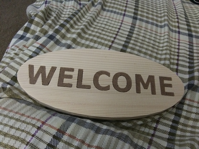
I attempted to carve out and inlay some letters to make a welcome sign. Overall I'm not too unhappy with the way it turned out.The letters were cut
from a crappy piece of project board that led to their frayed appearance. There isn't too many places around here to buy lumber so I went to the closest Home Depot store (The
Robber Barons of DIY supplies). They didn't have much of a selection of 1/8" thick wood so I bought a 2'x4'x1/8' project board to experiment with. I'll mail order some nice hardwood
vaneer now that I'm confident its going to produce some nice results.
Edited 2 time(s). Last edit at 08/18/2019 11:15AM by Shank man.
|
Re: MPCNC August 18, 2019 07:31PM |
Registered: 6 years ago Posts: 1,863 |
I have too many things presently doing do not have enough time in a single day to complete.
No, I am not praying for longer days. I have too much to do now if they were longer I would never get caught up.
Waiting for the next season where we will have less to do.
I have every thing done except printing a Power Supply enclosure and giving all the electronics there own dust masks, so to speak.
Actually they will have a dust filters so only clean air will be blowing threw the electronics cases.
Printed my Vacuum attachment for my Dewalt DW660 and I should be caving very soon...
Computer Programmer / Electronics Technician
|
Re: MPCNC September 18, 2019 09:13PM |
Registered: 6 years ago Posts: 1,863 |
Had stopped working on my MPCNC project for some time now, It is time to start and finish this up.
I have decided on which LCD display Case, Power Supply case and Arduino and Ramps 1.6 case will be printed.
An now 3D Printing the final pieces to finish the Arduino enclosure, then a quick reroute of the wiring.
Will be ready to start my first Carving.
When finished will add a second tool, a hot-end from my Hictop 3D Printers design as have plenty of spares.
It should be simple enough to make any changes to the MPCNC an easily 3d Print PLA, and ABS.
Should be easy to design a solid 300x300 hot-bed assembly to be attached to the MPCNC carving table.
One that has four corner leveling thumb screws, and manually set the nozzle start location.
Finished pictures to follow.
Computer Programmer / Electronics Technician
|
Re: MPCNC September 22, 2019 08:49AM |
Registered: 6 years ago Posts: 1,863 |
I was about to print final parts, discovered that after copying the G-code files from my computer to the SD card.
That MY PC incorrectly copied the file because of a USB driver corruption, caused file to make the 3D Print fail.
Failure appeared a lot like a layer shift on the print gave it the appearance of a under-extruded ghost image.
It also looked as though I had clogged the nozzle, but a quick check proved this to be incorrect diagnosis.
After re-installing the SD Card Reader USB Driver I again moved the G code to the 3D Printer this time with success.
I liked this case so well that I am posting the link here so everyone can see.
This slick little case could be modified for any project.
[www.thingiverse.com]
Made the Front plate without logo
Edited 2 time(s). Last edit at 09/22/2019 08:52AM by Roberts_Clif.
Computer Programmer / Electronics Technician
That MY PC incorrectly copied the file because of a USB driver corruption, caused file to make the 3D Print fail.
Failure appeared a lot like a layer shift on the print gave it the appearance of a under-extruded ghost image.
It also looked as though I had clogged the nozzle, but a quick check proved this to be incorrect diagnosis.
After re-installing the SD Card Reader USB Driver I again moved the G code to the 3D Printer this time with success.
I liked this case so well that I am posting the link here so everyone can see.
This slick little case could be modified for any project.
[www.thingiverse.com]
Made the Front plate without logo


Edited 2 time(s). Last edit at 09/22/2019 08:52AM by Roberts_Clif.
Computer Programmer / Electronics Technician
This second MPCNC build was kept small as space in my apartment is limited. Some improvements
were made over my 1st build. I left off the homing limit switches and made a waste board with more clamping points. All of the printed parts were done in black PLA+ at 300 micron layers and a 65% infill. I made a extra effort to ensure all of the tubes were cut to exact lengths. The overall build cost was the same at just under $285.00. It is a cheap CNC but the sacrifice is the amount of time it takes to build it. All told it took 9+ hours to assemble and then on top of that is the godawful amount of time it took to print the parts. Rather than trying to reuse the parts from my first one, I sold it on Craigslist, for a little under the build cost, to make room for this new one.
It took a long time to wrap my head around not needing end stops for homing but I finally came to the conclusion that they just aren't needed. Where ever you park the spindle is home after a co-ordinate reset.
One of the custom commands in the Smart Controller menu is to reset all co-ordinates. The co-ordinates need to be reset prior to starting all engraving jobs. They can also be reset by hitting the reset button on the RAMPS board or reset button on the Smart Controller or by powering the controller off and on. Oddly enough adding a G92 X0 Y0 Z0 command to the start G-code has no affect. The only real reason to use X,Y limit switches is for the auto squaring function but with this small of a build I can just manually jostle the axes back into place if need be. And then there is the added benefit of less wires to manage.
Much like printing jobs, some carving jobs take a long time to complete and just like with my printers I prefer
to load my G-code onto a SD card. Since I already had a Arduino Mega 2560 I bought
an inexpensive RAMPS along with a full Graphics Smart Controller and printed out a Prusa type controller enclosure to contain them. I like the enclosure design but the downside to using it is that there is no access to the USB port. So If I need to make changes to the firmware or swap out a driver, I'll need to partially dissemble the box to gain access. I found some black 4 conductor 20 awg PUR tool cord to use for the motor cables but ended up cutting them too short. I didn't figure in the loop back length needed for the cable chain. My intention was to distance the controller well away from the MPCNC so the cooling fan wouldn't suck in so much dust. Now I'll either have to extend the motor cables or add a fan filter.
The spoil board is made out of 1/2" MDF with 25, 5/16 T-nuts at a 95mm spacing.
I use bolts to hold down my work piece . A bit overkill but it eliminates any chance of the work piece from moving during the carving process. Bolting down the work piece at its opposing corners is enough to keep it in place. In the future I hold down clamps will be used in place of the bolts.
I use flat washers as spacers to elevate the work piece above the waste board when doing through cuts to prevent damaging the board. Making the spoil board took a bit of effort and expense and I want to preserve it for as long as possible. I realize this is contrary to the purpose of the board.
Somehow when buying all of the parts I overlooked the purchase of a ACME rod needed for the Z axis. In order to keep the build progressing I used a piece of M8 stainless steel threaded rod and a brass hex nut. These have served me well on my printer builds so I'll probably keep it this way. It works just the same. I only needed to change the steps in the firmware to accommodate this.
I've also switched from ESTLCAM to Shapeoko's Carbide Create CAM software to make the tool paths. The downside to C.C. is that it doesn't have a animated tool path preview although it is more intuitive with a nice library of files to choose from. But it does create the G-code with a .nc extension that my controller doesn't recognize. I have to change the .nc extension to .gcode to make it usable.
I use Oramask vinyl stencil material for masking on the engravings I intend to add paint. It is easy to apply and it leaves a nice clean edge when cut with a V-bit. A End Mill leaves it a bit ragged but good enough to prevent any paint from bleeding into the wood grain. Once the paint is dry the mask is easy to remove. This isn't Pinterest so I'll refrain from posting too many pictures of my still basic carves to keep the administrators happy.
were made over my 1st build. I left off the homing limit switches and made a waste board with more clamping points. All of the printed parts were done in black PLA+ at 300 micron layers and a 65% infill. I made a extra effort to ensure all of the tubes were cut to exact lengths. The overall build cost was the same at just under $285.00. It is a cheap CNC but the sacrifice is the amount of time it takes to build it. All told it took 9+ hours to assemble and then on top of that is the godawful amount of time it took to print the parts. Rather than trying to reuse the parts from my first one, I sold it on Craigslist, for a little under the build cost, to make room for this new one.


It took a long time to wrap my head around not needing end stops for homing but I finally came to the conclusion that they just aren't needed. Where ever you park the spindle is home after a co-ordinate reset.
One of the custom commands in the Smart Controller menu is to reset all co-ordinates. The co-ordinates need to be reset prior to starting all engraving jobs. They can also be reset by hitting the reset button on the RAMPS board or reset button on the Smart Controller or by powering the controller off and on. Oddly enough adding a G92 X0 Y0 Z0 command to the start G-code has no affect. The only real reason to use X,Y limit switches is for the auto squaring function but with this small of a build I can just manually jostle the axes back into place if need be. And then there is the added benefit of less wires to manage.
Much like printing jobs, some carving jobs take a long time to complete and just like with my printers I prefer
to load my G-code onto a SD card. Since I already had a Arduino Mega 2560 I bought
an inexpensive RAMPS along with a full Graphics Smart Controller and printed out a Prusa type controller enclosure to contain them. I like the enclosure design but the downside to using it is that there is no access to the USB port. So If I need to make changes to the firmware or swap out a driver, I'll need to partially dissemble the box to gain access. I found some black 4 conductor 20 awg PUR tool cord to use for the motor cables but ended up cutting them too short. I didn't figure in the loop back length needed for the cable chain. My intention was to distance the controller well away from the MPCNC so the cooling fan wouldn't suck in so much dust. Now I'll either have to extend the motor cables or add a fan filter.

The spoil board is made out of 1/2" MDF with 25, 5/16 T-nuts at a 95mm spacing.
I use bolts to hold down my work piece . A bit overkill but it eliminates any chance of the work piece from moving during the carving process. Bolting down the work piece at its opposing corners is enough to keep it in place. In the future I hold down clamps will be used in place of the bolts.
I use flat washers as spacers to elevate the work piece above the waste board when doing through cuts to prevent damaging the board. Making the spoil board took a bit of effort and expense and I want to preserve it for as long as possible. I realize this is contrary to the purpose of the board.

Somehow when buying all of the parts I overlooked the purchase of a ACME rod needed for the Z axis. In order to keep the build progressing I used a piece of M8 stainless steel threaded rod and a brass hex nut. These have served me well on my printer builds so I'll probably keep it this way. It works just the same. I only needed to change the steps in the firmware to accommodate this.
I've also switched from ESTLCAM to Shapeoko's Carbide Create CAM software to make the tool paths. The downside to C.C. is that it doesn't have a animated tool path preview although it is more intuitive with a nice library of files to choose from. But it does create the G-code with a .nc extension that my controller doesn't recognize. I have to change the .nc extension to .gcode to make it usable.
I use Oramask vinyl stencil material for masking on the engravings I intend to add paint. It is easy to apply and it leaves a nice clean edge when cut with a V-bit. A End Mill leaves it a bit ragged but good enough to prevent any paint from bleeding into the wood grain. Once the paint is dry the mask is easy to remove. This isn't Pinterest so I'll refrain from posting too many pictures of my still basic carves to keep the administrators happy.


|
Re: MPCNC March 21, 2020 03:30PM |
Registered: 6 years ago Posts: 1,863 |
Still procrastinating, have not finished the layout on my controller case. Have all the parts and know how I want them laid out on my case.
Including wiring to the 8 pin mic sockets and plugs, similar to the CR-10 3D Printers.
Still procrastinating testing how to add another stepper motor driver to my ramps 1.6 driver board so I can have a extruder tool for 3D Printing.
And was waiting for warmer weather to test with the Dewalt Dw660 as it is quite loud inside, though I have tested printing a sketch in pencil with a lot of fine detail.
Then I want to place a shed not too far from the house where this project can reside, using a OctoPrint w/cam for year around use to build all sorts of projects.
And maybe I am overthinking this, as My 3D Printer has dual Z stepper motors so I could place my Dual Stepper XY in series and have E0 / E1 for 3D Printing.
As long as I wire them to turn in opposite directions as one spins clockwise the other counter clockwise. An do not use Dual End-stops on the XY Axis.
Edited 9 time(s). Last edit at 03/21/2020 04:19PM by Roberts_Clif.
Computer Programmer / Electronics Technician
Including wiring to the 8 pin mic sockets and plugs, similar to the CR-10 3D Printers.
Still procrastinating testing how to add another stepper motor driver to my ramps 1.6 driver board so I can have a extruder tool for 3D Printing.
And was waiting for warmer weather to test with the Dewalt Dw660 as it is quite loud inside, though I have tested printing a sketch in pencil with a lot of fine detail.

Then I want to place a shed not too far from the house where this project can reside, using a OctoPrint w/cam for year around use to build all sorts of projects.
And maybe I am overthinking this, as My 3D Printer has dual Z stepper motors so I could place my Dual Stepper XY in series and have E0 / E1 for 3D Printing.
As long as I wire them to turn in opposite directions as one spins clockwise the other counter clockwise. An do not use Dual End-stops on the XY Axis.
Edited 9 time(s). Last edit at 03/21/2020 04:19PM by Roberts_Clif.
Computer Programmer / Electronics Technician
Quote
Roberts_Clif
Still procrastinating, have not finished the layout on my controller case. Have all the parts and know how I want them laid out on my case.
Including wiring to the 8 pin mic sockets and plugs, similar to the CR-10 3D Printers.
Still procrastinating testing how to add another stepper motor driver to my ramps 1.6 driver board so I can have a extruder tool for 3D Printing.
And was waiting for warmer weather to test with the Dewalt Dw660 as it is quite loud inside, though I have tested printing a sketch in pencil with a lot of fine detail.
[attachment 114924 Sena.jpg]
Then I want to place a shed not too far from the house where this project can reside, using a OctoPrint w/cam for year around use to build all sorts of projects.
And maybe I am overthinking this, as My 3D Printer has dual Z stepper motors so I could place my Dual Stepper XY in series and have E0 / E1 for 3D Printing.
As long as I wire them to turn in opposite directions as one spins clockwise the other counter clockwise. An do not use Dual End-stops on the XY Axis.
I need a spot for mine too. If the landlord finds out I'm engraving on the kitchen table they'd probably throw me out. So far none of my neighbors have
complained about the noise. I try to keep my jobs under 4 hours and do them in the daytime when most people are at work. I really need
an enclosure, vacuum set up and a stable platform to mount the engraver on.
I have my X & Y motors wired in series so I'm only using 3 of the 5 available drivers on the controller board. E0 & E1 are open. Maybe by wiring in series and reassigning some pins you should be able to wire in a extruder.
|
Re: MPCNC March 22, 2020 09:18AM |
Registered: 6 years ago Posts: 1,863 |
Thank you. The information is greatly appreciated.
I knew this could be done, though at the same time was a little worried about burning up the Driver modules.
This means I can spend the rest of the week-end completing the new case with my mic connectors.
No sorry made a mistake, I have to weed the flower beds, trim the rose bushes and basic yard work.
But maybe this evening I can get started on wiring the case to the mic sockets.
Again Thank You.
Question to the forum which ramps Driver modules would allow the best operation for driving dual Stepper motors in series.
Edited 1 time(s). Last edit at 03/22/2020 09:23AM by Roberts_Clif.
Computer Programmer / Electronics Technician
|
Re: MPCNC - New Primo July 31, 2021 01:47PM |
Registered: 9 years ago Posts: 204 |
I chose the Primo version for my third build. I really like the redesigned parts and think they give the machine a sleek and refined look.
With this new design there are a few differences between the Primo and the Burly.
The Primo uses 10mm GT2 belts instead of 6mm ones and integrates the belt tension adjusters into the corner pieces.
All 608 bearing idlers have been replaced with 20 tooth GT2 idlers reducing the bearing count from 53 to 45.
The conduit spacers (AKA: Spacer_Corner_*_Burly) are no longer needed to assemble the corners.
Despite of having the same footprint as a Burly, the Primo has a slightly smaller work area. It has a overall footprint of 610mm x 610mm but only has a 290mm x 270mm x 77mm cutting area. This is due to the redesigned corners.
My Burlys were built using 84 Oz stepper motors and this Primo was built with 61 Oz ones. There has been no noticable performance difference using the smaller motors. After approximately 70 hours of cutting time there have been no axis skips and the motors don't heat up much beyond room temperature.
All of the Black-PLA and Blue-ABS parts were printed on a Piper printer whose design happens to be based on a MPCNC. Everything was printed with 0.25 layer height and a infill set at the recommended 45% with the exception of the core that has a 70% infill.
Once the printing was finished the Piper was cannibalized for its 608 bearings and stepper motors. The rest of the parts were trashed. The oddball printer had served its purpose.
This now one piece core is a substantial print and took 32 hours. Mine was printed with 0.25 layers and a 70% infill. A couple of hours could have been shaved off had I sliced with a variable 70-30-70 percent infill setting.
I found some 4-pole, M12 receptacles and some 3-meter 90-degree single ended cables from AutomationDirect.com and figured they would work great for this application. I remixed an ancient Minion Controller enclosure from Thingiverse to mount the receptacles. Also the cooling method was changed to use a single 60mm x 10mm fan instead of two 50mm x 5mm fans. Two 50mm fans seemed a little excessive to me. More fans will only suck in more sawdust.

With this new design there are a few differences between the Primo and the Burly.
The Primo uses 10mm GT2 belts instead of 6mm ones and integrates the belt tension adjusters into the corner pieces.

All 608 bearing idlers have been replaced with 20 tooth GT2 idlers reducing the bearing count from 53 to 45.
The conduit spacers (AKA: Spacer_Corner_*_Burly) are no longer needed to assemble the corners.
Despite of having the same footprint as a Burly, the Primo has a slightly smaller work area. It has a overall footprint of 610mm x 610mm but only has a 290mm x 270mm x 77mm cutting area. This is due to the redesigned corners.
My Burlys were built using 84 Oz stepper motors and this Primo was built with 61 Oz ones. There has been no noticable performance difference using the smaller motors. After approximately 70 hours of cutting time there have been no axis skips and the motors don't heat up much beyond room temperature.
All of the Black-PLA and Blue-ABS parts were printed on a Piper printer whose design happens to be based on a MPCNC. Everything was printed with 0.25 layer height and a infill set at the recommended 45% with the exception of the core that has a 70% infill.
Once the printing was finished the Piper was cannibalized for its 608 bearings and stepper motors. The rest of the parts were trashed. The oddball printer had served its purpose.
This now one piece core is a substantial print and took 32 hours. Mine was printed with 0.25 layers and a 70% infill. A couple of hours could have been shaved off had I sliced with a variable 70-30-70 percent infill setting.

I found some 4-pole, M12 receptacles and some 3-meter 90-degree single ended cables from AutomationDirect.com and figured they would work great for this application. I remixed an ancient Minion Controller enclosure from Thingiverse to mount the receptacles. Also the cooling method was changed to use a single 60mm x 10mm fan instead of two 50mm x 5mm fans. Two 50mm fans seemed a little excessive to me. More fans will only suck in more sawdust.

|
Re: MPCNC May 26, 2022 02:26AM |
Registered: 2 years ago Posts: 1 |
 your picture is nice. thanks for sharing. Go
Sorry, only registered users may post in this forum.