Marlin firmware as laser cutter
Posted by Humpster
|
Marlin firmware as laser cutter August 12, 2015 09:05PM |
Registered: 10 years ago Posts: 4 |
I am stuck. I thought I could just use Marlin firmware to control the custom 3d printed laser cutter.
I had seen some fellas use one of those chinese laser cutters and converted it with ramps 1.4. I was thinking I could just adjust the settings and use the fan D10 connection to control the laser diode I have.
[http://www.cnczone.com/forums/general-laser-engraving-cutting-machine-discussion/256422-cnc-3.html]
Anyone out there convert a ramps 1.4 w/ 2560 mega into a diode laser cutter? Would love to chat and see what firmware you use / how to configure.
|
Re: Marlin firmware as laser cutter August 13, 2015 12:30PM |
Registered: 9 years ago Posts: 49 |
|
Re: Marlin firmware as laser cutter August 14, 2015 10:20AM |
Registered: 8 years ago Posts: 59 |
I did the same to my Prusa i3: M106 S255 to turn the laser on, M106 S0 to turn it off, and M106 S30 to get a dim dot to locate my piece (the G4 g-code could be used to hold the laser in one place while I locate my piece).
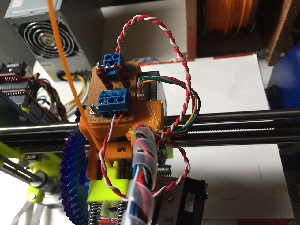
I drive my laser (from a DVD burner) through a few high-watt resistors (who needs a current source anyway!)
I drive my laser (from a DVD burner) through a few high-watt resistors (who needs a current source anyway!)
|
Re: Marlin firmware as laser cutter August 15, 2015 04:21PM |
Registered: 9 years ago Posts: 47 |
|
Re: Marlin firmware as laser cutter August 16, 2015 07:22PM |
Registered: 9 years ago Posts: 49 |
|
Re: Marlin firmware as laser cutter August 16, 2015 10:55PM |
Registered: 8 years ago Posts: 59 |
I did a similar thing to the 3ders.org laser cutter/engraver.
My inspiration came from Groover's instructable:
Pocket Laser Engraver
He (and I) used a laser from a DVD burner. The instructable shows you the things you can do with it. A red DVD burner laser is good for a few hundred milliwatts. The laser used in the 3ders.org link is a blue laser good for a couple of watts. It would need some cooling.
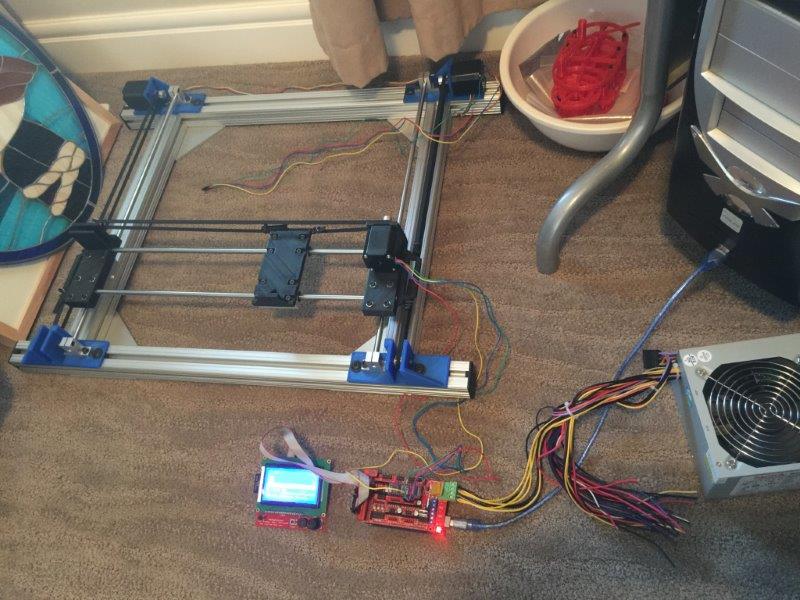
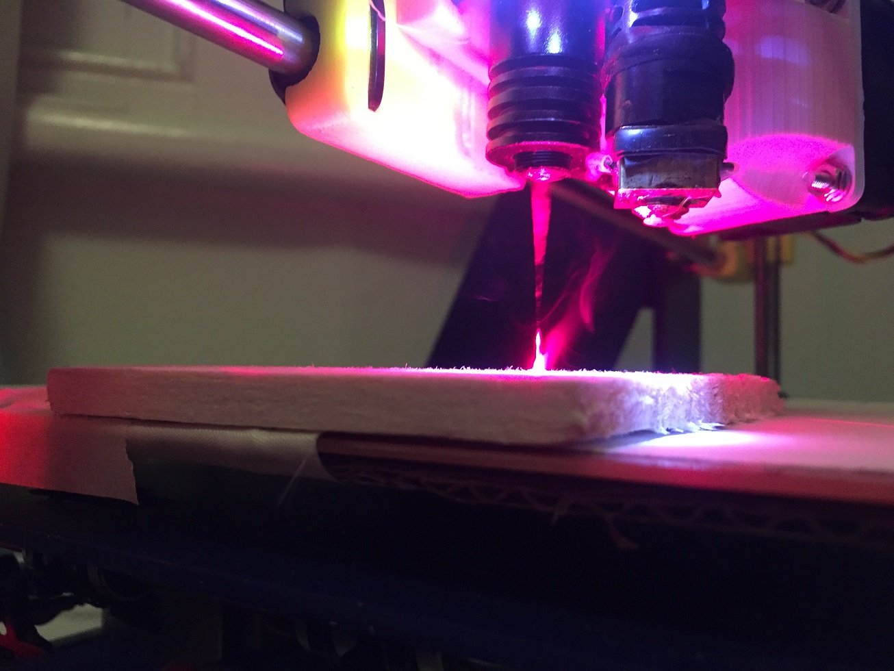
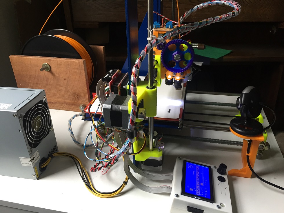
Using my 3D printer (Prusa i3) gave me a larger work area than the pocket laser engraver, and also gave me Z-axis control. This provides a useful way to adjust for the laser focal length, but also to adjust for engraving on objects of different heights. I used it to print the same thing over slightly displaced with the laser raised a little each time; I found that what looked like the best focus was not the best height for cutting/engraving. At the best height I found the laser 'circle' was larger, but the point in the middle must have been tighter.
Another benefit of using my 3D printer is that it is already setup to read from the SD card. That makes things a little easier.
Groover uses Inkscape to generate the cutting/engraving files. He runs grbl on an arduino controlling his Pocket Laser Engraver, and he manipulates the files somehow with his own 'gcodesender' script. Well, it turns out that Marlin is quite capable of interpreting the g-codes from Inkscape, so grbl and Gcodesender aren't necessary. Marlin even accepts the G2 and G3 arc moves output by Inkscape for curved paths.
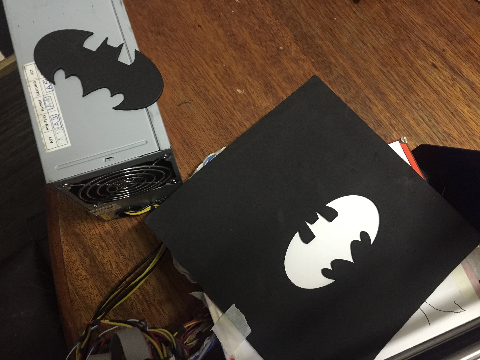
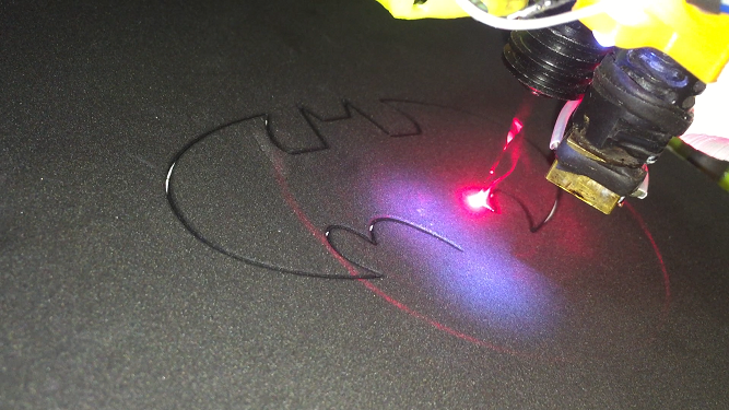
I do some manipulation of the g-code files from Inkscape before I put them on the SD card. I do a bit of 'find and replace'. The Inkscape output files (using the 'gcodetools' extension) separates each path into a group of g-codes. I turn the laser off at the end of each segment, turn it on at the start of each segment, set the cutting engraving speed at the start of each segment, set a higher speed at the end of each segment so it isn't too slow moving between cutting paths). Sometimes now I let it move slowly between segments.. to give the laser a chance to cool. I also might change the order of the paths that are cut (for example, if you are cutting a pattern inside, say, a circle, I would cut the circle last, because if it is cut first, the foam - or whatever - might move during the remainder of the cutting process).
I have only done a little bit of raster engraving, and have used 305engineering's extension 'Raster 2 Laser Gcode generator'. For what I have done so far, it works well.
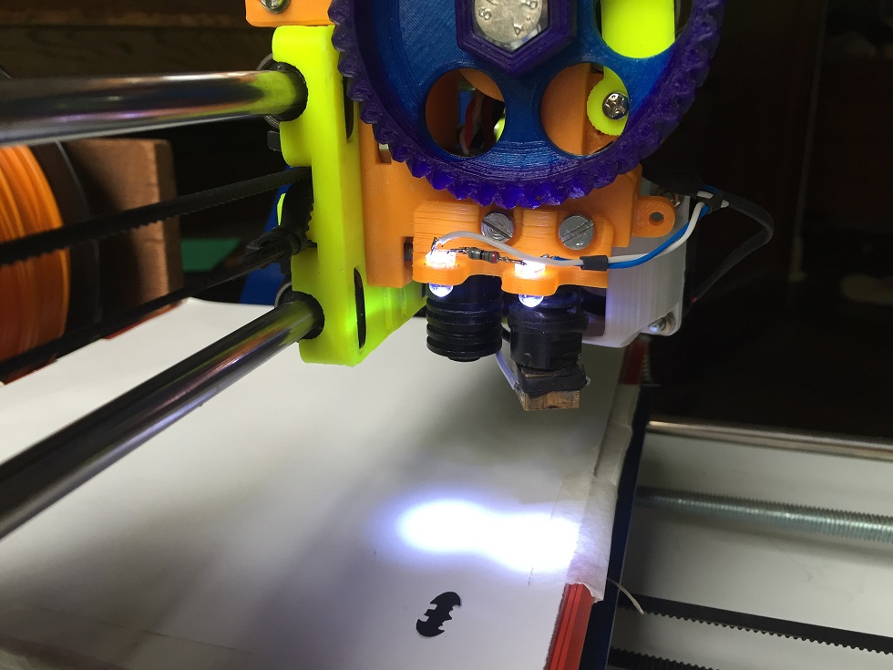
As mentioned, the way I turn the laser on and off is with the M106 g-code. It is the g-code that operates the print fan: M106 S255 turns it on fully, M106 S0 turns it off fully. And I connect the laser to D9, where the print fan would normally connect. The Marlin configuration.h file must have the motherboard set to a 'EFB' type, so that it knows there is a fan (that is what the 'F' in EFB means) connected to D9. I don't use a current source to drive my laser, just some hi watt series resistors (and I have a capacitor across the laser to provide some protection).
I reprinted the Wade extruder to fit the laser housing I bought. So now going between 3d printing and laser engraving/cutting is a matter of minutes... at the most! My new extruder lets the J-head fan swivel to help cool the laser too... Not sure how much it helps, but it certainly doesn't hurt.
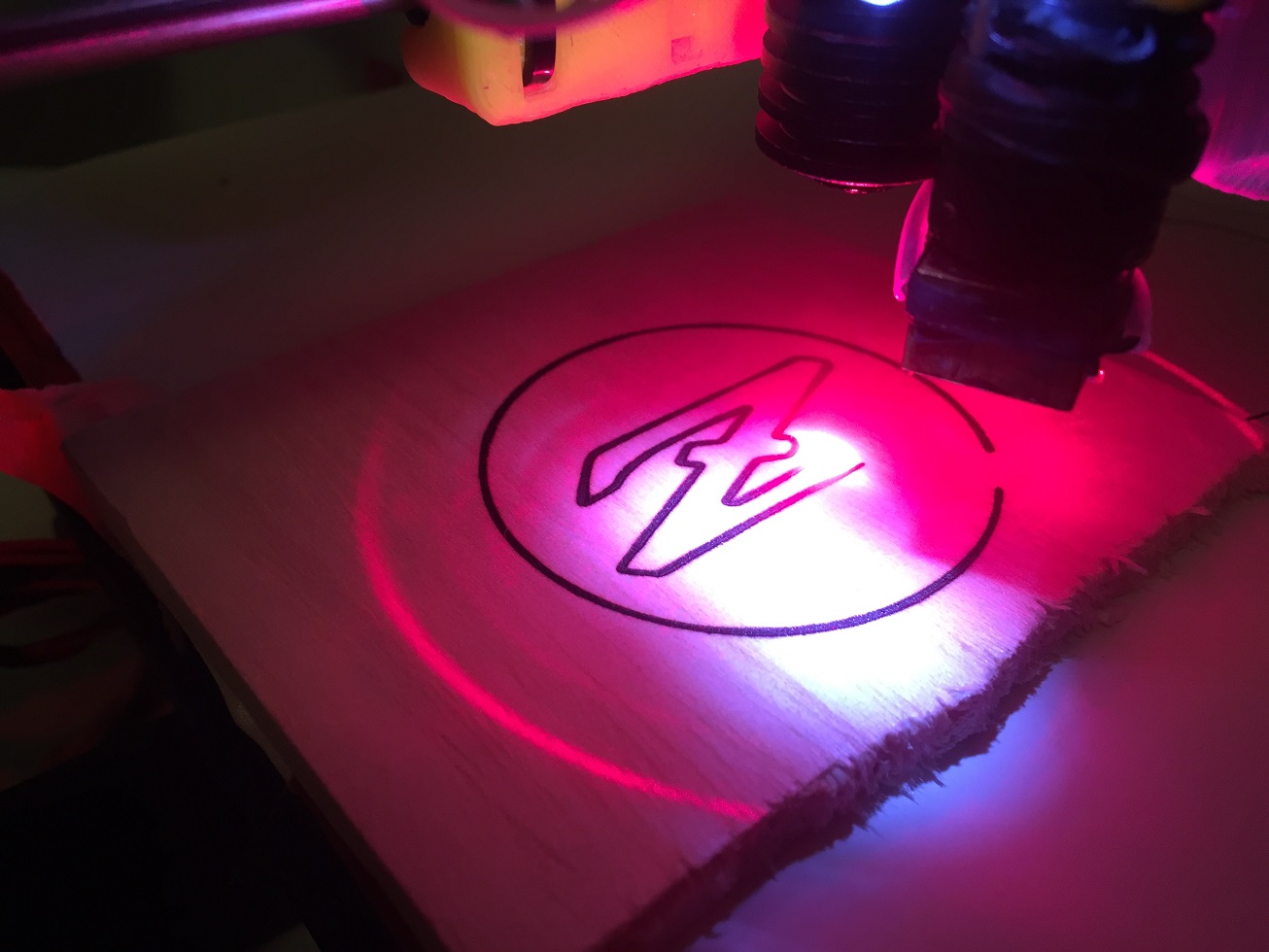
I have found engraving wood a little bit tricky in that it doesn't always start to burn at the start of a path. Once started it seems to keep going, but it needs to reliably start. I think with a higher watt blue laser like that used in the 3ders.org link, it would be much less of a problem. However, I have been tinkering and I think I am onto something. A bit more playing around needed there.
Of course, before I got started, I got a pair of laser glasses. Don't forget them!.
I printed a mount for a webcam on my printer so I can box it up and watch on the laptop (there are kids around). I find I mostly put the box on it, but check it by peering in the top with the glasses on.
My inspiration came from Groover's instructable:
Pocket Laser Engraver
He (and I) used a laser from a DVD burner. The instructable shows you the things you can do with it. A red DVD burner laser is good for a few hundred milliwatts. The laser used in the 3ders.org link is a blue laser good for a couple of watts. It would need some cooling.
Using my 3D printer (Prusa i3) gave me a larger work area than the pocket laser engraver, and also gave me Z-axis control. This provides a useful way to adjust for the laser focal length, but also to adjust for engraving on objects of different heights. I used it to print the same thing over slightly displaced with the laser raised a little each time; I found that what looked like the best focus was not the best height for cutting/engraving. At the best height I found the laser 'circle' was larger, but the point in the middle must have been tighter.
Another benefit of using my 3D printer is that it is already setup to read from the SD card. That makes things a little easier.
Groover uses Inkscape to generate the cutting/engraving files. He runs grbl on an arduino controlling his Pocket Laser Engraver, and he manipulates the files somehow with his own 'gcodesender' script. Well, it turns out that Marlin is quite capable of interpreting the g-codes from Inkscape, so grbl and Gcodesender aren't necessary. Marlin even accepts the G2 and G3 arc moves output by Inkscape for curved paths.
I do some manipulation of the g-code files from Inkscape before I put them on the SD card. I do a bit of 'find and replace'. The Inkscape output files (using the 'gcodetools' extension) separates each path into a group of g-codes. I turn the laser off at the end of each segment, turn it on at the start of each segment, set the cutting engraving speed at the start of each segment, set a higher speed at the end of each segment so it isn't too slow moving between cutting paths). Sometimes now I let it move slowly between segments.. to give the laser a chance to cool. I also might change the order of the paths that are cut (for example, if you are cutting a pattern inside, say, a circle, I would cut the circle last, because if it is cut first, the foam - or whatever - might move during the remainder of the cutting process).
I have only done a little bit of raster engraving, and have used 305engineering's extension 'Raster 2 Laser Gcode generator'. For what I have done so far, it works well.
As mentioned, the way I turn the laser on and off is with the M106 g-code. It is the g-code that operates the print fan: M106 S255 turns it on fully, M106 S0 turns it off fully. And I connect the laser to D9, where the print fan would normally connect. The Marlin configuration.h file must have the motherboard set to a 'EFB' type, so that it knows there is a fan (that is what the 'F' in EFB means) connected to D9. I don't use a current source to drive my laser, just some hi watt series resistors (and I have a capacitor across the laser to provide some protection).
I reprinted the Wade extruder to fit the laser housing I bought. So now going between 3d printing and laser engraving/cutting is a matter of minutes... at the most! My new extruder lets the J-head fan swivel to help cool the laser too... Not sure how much it helps, but it certainly doesn't hurt.
I have found engraving wood a little bit tricky in that it doesn't always start to burn at the start of a path. Once started it seems to keep going, but it needs to reliably start. I think with a higher watt blue laser like that used in the 3ders.org link, it would be much less of a problem. However, I have been tinkering and I think I am onto something. A bit more playing around needed there.
Of course, before I got started, I got a pair of laser glasses. Don't forget them!.
I printed a mount for a webcam on my printer so I can box it up and watch on the laptop (there are kids around). I find I mostly put the box on it, but check it by peering in the top with the glasses on.
Attachments:
open | download - cutting batman - black craft foam 2.JPG (544.1 KB)
open | download - laser focus.JPG (270.1 KB)
open | download - cutting batman - black craft foam.PNG (488.7 KB)
open | download - 3D printer and laser engraver with webcam.JPG (227.4 KB)
open | download - engraving balsa wood.JPG (207.6 KB)
open | download - laser and j-head together.JPG (165.3 KB)
open | download - laser driver.JPG (223.9 KB)
|
Re: Marlin firmware as laser cutter January 13, 2016 01:09PM |
Registered: 8 years ago Posts: 10 |
|
Re: Marlin firmware as laser cutter January 13, 2016 01:37PM |
Admin Registered: 16 years ago Posts: 13,884 |
... AFAIK the fan output is a PWM signal, so with a multimeter you'll see the averaged voltage only.
You need an oszilloscope to see/measure the exact timings and voltage levels ...
Viktor
--------
Aufruf zum Projekt "Müll-freie Meere" - [reprap.org] -- Deutsche Facebook-Gruppe - [www.facebook.com]
Call for the project "garbage-free seas" - [reprap.org]
You need an oszilloscope to see/measure the exact timings and voltage levels ...
Viktor
--------
Aufruf zum Projekt "Müll-freie Meere" - [reprap.org] -- Deutsche Facebook-Gruppe - [www.facebook.com]
Call for the project "garbage-free seas" - [reprap.org]
|
Re: Marlin firmware as laser cutter January 13, 2016 03:42PM |
Registered: 8 years ago Posts: 10 |
Quote
VDX
... AFAIK the fan output is a PWM signal, so with a multimeter you'll see the averaged voltage only.
You need an oszilloscope to see/measure the exact timings and voltage levels ...
Interesting... I am still pretty new to all this so forgive me. Just to confirm the standard Output of the D9 block on RAMPs 1.4 is sufficient as the laser power source, assuming a 200-500mW laser?
*update* I just tried the laser on D9 and it did not power, even manually setting M106 S255
Edited 1 time(s). Last edit at 01/13/2016 03:57PM by jeyton.
|
Re: Marlin firmware as laser cutter January 13, 2016 04:15PM |
Registered: 8 years ago Posts: 59 |
As Viktor said, it's a PWM output. So at max output, you should be measuring around 12Vdc. My laser is 200-300W and I have no problem driving it. Do you get anything at D9 with the laser driver disconnected?
Have you set the motherboard type to 'EFB' in the configuration.h file? With no 'F' in the middle, M106 will not do anything (M106 drives the fan output, the 'F' in EFB tells Marlin a fan is connected).
Have you set the motherboard type to 'EFB' in the configuration.h file? With no 'F' in the middle, M106 will not do anything (M106 drives the fan output, the 'F' in EFB tells Marlin a fan is connected).
|
Re: Marlin firmware as laser cutter January 13, 2016 05:03PM |
Registered: 8 years ago Posts: 10 |
Yes I do:
// The following define selects which electronics board you have.
// Please choose the name from boards.h that matches your setup
#ifndef MOTHERBOARD
#define MOTHERBOARD BOARD_RAMPS_13_EFB
#endif
I do get voltage out from D9 when I turn it on, my multimeter shows it at 1.5v but I presume thats because its PWM and my meter is not an oscillator. It seems I need to do something with TTL which my laser driver doesn't have. I am a bit lost on how to wire it to the RAMPS even if I did have a TTL pin on my driver.
|
Re: Marlin firmware as laser cutter January 13, 2016 05:19PM |
Admin Registered: 16 years ago Posts: 13,884 |
... caution! -- the MOSFET's will switch your PS-voltage, what's 12V (or 24V if supplied with), what will damage any TTL input!
I don't know exactly, if the Arduino 2560 has 5V or 3.3V digital output - if 5V, then you can wire one of the sparse digital I/O-pins directly to your TTL-input and GND of the RAMPS to the GND of the laser driver.
If 3.3V, then you'll need a 5V voltage driver -- e.g. a 7805 voltage regulator, to get 5V from the 12V, and a transistor for switching the 5V to the TTL input ...
Viktor
--------
Aufruf zum Projekt "Müll-freie Meere" - [reprap.org] -- Deutsche Facebook-Gruppe - [www.facebook.com]
Call for the project "garbage-free seas" - [reprap.org]
|
Re: Marlin firmware as laser cutter January 13, 2016 05:44PM |
Registered: 8 years ago Posts: 59 |
A multimeter will read average voltage. It doesn't matter if it's PWM. Make sure you have it set on DC Volts. The pulses are 12V. With the S255 setting you are using, the pulse width is 100% and the output just looks like a steady 12V DC. And with S128 (for example), each pulse will be at 50% duty cycle (the pulse would go for 1msec, and repeat every 2msec). The multimeter will read the average, i.e. 6V (or thereabouts).
If you want to know if the D9 output is working, try measuring it with the laser driver disconnected.
With S0 and S255 you are basically switching 12V to the driver. Do you have any info on the driver? What supply it requires?
I just had a look at the RAMPS and Arduino schematics, it all looks to be 5V.
|
Re: Marlin firmware as laser cutter January 13, 2016 06:31PM |
Admin Registered: 16 years ago Posts: 13,884 |
... if the driver has a TTL input, then it's meant for 5V input -- any voltage above 6Volts will (or already have) destroy the input electronics of the driver !!!
Viktor
--------
Aufruf zum Projekt "Müll-freie Meere" - [reprap.org] -- Deutsche Facebook-Gruppe - [www.facebook.com]
Call for the project "garbage-free seas" - [reprap.org]
Viktor
--------
Aufruf zum Projekt "Müll-freie Meere" - [reprap.org] -- Deutsche Facebook-Gruppe - [www.facebook.com]
Call for the project "garbage-free seas" - [reprap.org]
|
Re: Marlin firmware as laser cutter January 13, 2016 07:01PM |
Registered: 8 years ago Posts: 10 |
|
Re: Marlin firmware as laser cutter January 13, 2016 07:33PM |
Admin Registered: 16 years ago Posts: 13,884 |
... what input type is your laser driver?
Common laser drivers have either a TTL input, which needs defined voltages in the ranges of 0V to 0.7V for LOW, and mostly +2.5V to +5V for HIGH.
- or they have an analog input, which can be driven with an analogue voltage between 0V to 5V - here the output power is related to the voltage.
But an analog input will behave identical to a TTL, when driven with only 0V/GND or +5V signals ...
Edited 1 time(s). Last edit at 01/13/2016 07:34PM by VDX.
Viktor
--------
Aufruf zum Projekt "Müll-freie Meere" - [reprap.org] -- Deutsche Facebook-Gruppe - [www.facebook.com]
Call for the project "garbage-free seas" - [reprap.org]
|
Re: Marlin firmware as laser cutter January 13, 2016 09:47PM |
Registered: 8 years ago Posts: 59 |
On first read of your email, I thought 'Hooray, you got it to work, well done!'. You found a way. Don't worry about D9, you don't need it now. As far as PWM goes, those outputs pulse at 500Hz. That's too fast for dithering anyway. I think you will need to do the dithering in your g-code. I generally just have it all on or all off. There have been some occasions i have used the PWM at a lower output, and that was to create a weak dot (too weak to burn) so that I could centre my piece accurately using the initial laser position as a reference. I have a grid marked out on my bed which is what I usually use to position pieces, but on the odd occasion I need to be more accurate, I use the laser on a low PWM setting.
But when I read you post a second time, it occurred to me that servo controllers output quite low duty cycles. I am not sure how the D6 output pin works, but even when a servo motor is told to move the maximum angle, the duty cycle is far below 100%. What output voltage do you measure from that pin.
And when I check M24, it tells me it is the g-code for writing to the SD card. Did you mean M280?
And again, what do you measure at D9 when you command M106 S255 with the laser driver disconnected?
|
Re: Marlin firmware as laser cutter January 13, 2016 10:42PM |
Registered: 8 years ago Posts: 10 |
You're right, I just checked and its output is 4.95v, which the laser seems to work best with around 5.25v. Also I presume the voltage from that servo pin is coming from the arduino's power supply ( USB ). This explains why the laser cuts (ok), using the 5v 600mA Wal-Wort from Aixiz but NOT using D6. Still searching for the answer to this...
Also, I meant M42 not M24, sorry...
I presume anyone who has this working is using an adjustable current TTL enabled laser diode driver am I right? That would allow using the D9 block to power the laser. I also presume with such driver the voltage of D9 being higher than whats typically recommended isn't too big of a problem as long as you have proper cooling on the driver and diode right?
Would this driver work well? Aixiz Driver
Edited 3 time(s). Last edit at 01/13/2016 11:59PM by jeyton.
|
Re: Marlin firmware as laser cutter January 14, 2016 03:26AM |
Registered: 8 years ago Posts: 5,232 |
#if MB(RAMPS_13_EF|| MB(RAMPS_13_EFF) || MB(AZTEEG_X3) || MB(AZTEEG_X3_PRO) #define FAN_PIN 6 // was D9 #else #define FAN_PIN 4 // IO pin. Buffer needed #endif
If you want to use M106/M107 commands with a 5V signal level, search Marlins code for "EFB" in all tabs until you find this piece of code in pins.h.
Change it to any servo pin you like ( mine is at pin 4 ) and connect it to the TTL input.
I also defined
// Increase the FAN pwm frequency. Removes the PWM noise but increases heating in the FET/Arduino
//#define FAST_PWM_FAN
in configuration.h to get smoother grayscale results.
Be aware that with red DVD LDs, grayscaling is almost impossible. ( at least on light colored surfaces )
Maybe if you find a program that allows to scale the PWM between user-selectable XXX-YYY instead of 000-255. ( I'm working on rewriting "305 Engineering"s inkscape extension. )
-Olaf
Edited 1 time(s). Last edit at 01/14/2016 03:30AM by o_lampe.
|
Re: Marlin firmware as laser cutter January 14, 2016 03:37AM |
Registered: 8 years ago Posts: 5,232 |
Quote
I presume anyone who has this working is using an adjustable current TTL enabled laser diode driver am I right? That would allow using the D9 block to power the laser. I also presume with such driver the voltage of D9 being higher than whats typically recommended isn't too big of a problem as long as you have proper cooling on the driver and diode right?
If the TTL input is in fact a MOSFET, you can probably use a higher voltage than 5V.
You can't switch the whole driver ON/OFF with such a fast PWM, because they often have a softstart behavior.
-Olaf
|
Re: Marlin firmware as laser cutter January 14, 2016 01:06PM |
Registered: 8 years ago Posts: 10 |
Quote
o_lampe
#if MB(RAMPS_13_EF
If you want to use M106/M107 commands with a 5V signal level, search Marlins code for "EFB" in all tabs until you find this piece of code in pins.h.
Change it to any servo pin you like ( mine is at pin 4 ) and connect it to the TTL input.
I also defined
// Increase the FAN pwm frequency. Removes the PWM noise but increases heating in the FET/Arduino
//#define FAST_PWM_FAN
in configuration.h to get smoother grayscale results.
Be aware that with red DVD LDs, grayscaling is almost impossible. ( at least on light colored surfaces )
Maybe if you find a program that allows to scale the PWM between user-selectable XXX-YYY instead of 000-255. ( I'm working on rewriting "305 Engineering"s inkscape extension. )
-Olaf
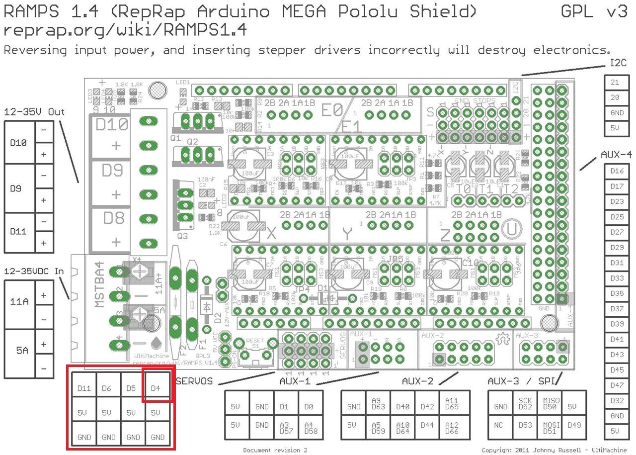
This is much appreciated thank you. I just knuckled down and bought a M160 2W diode, housing, glass lense, and driver. If I am understanding correctly I want to connect my driver to the servo pins. Orienting the RAMPS power block to the left, the servo pins would be as follows from bottom up: GRND, +5v, VCC (D11,D4,D5, or D6). If this is correct then I want to connect the driver ground and power to the appropriate pins and then connect the TTL to the VCC pin is that right?
|
Re: Marlin firmware as laser cutter January 15, 2016 03:39AM |
Registered: 8 years ago Posts: 5,232 |
The X-drive you linked to, is not identic to the TTL-version the page shows at the bottom. I'd contact the seller before you buy something wrong.
I also miss the potmeter to adjust your own current-max.
The M140 is pretty powerful. I had to reduce current to 1A or even lower, because my atmega 8bit CPU ( or the SD-card? ) isn't fast enough to engrave grayscale images with more than 900mm/min.
So the only way to make it look nice is to reduce current.
I'm using one of these drivers.
IMHO the multi-turn potmeter is a must to finetune current and it is self locking too. The second potmeter to reduce max LD voltage saved a few of my red DVD-LDs.
*added image of servo header
Edited 1 time(s). Last edit at 01/15/2016 03:42AM by o_lampe.
|
Re: Marlin firmware as laser cutter January 15, 2016 12:26PM |
Registered: 8 years ago Posts: 10 |
Correct the Driver is not current adjustable, but I did get confirmation from the seller on which driver to get for the diode and confirmed it is TTL after removal of a 10Kohm resistor next to the v+ pad. I may have to purchase another driver though if the 1.8a driver is too much for the feed rate. It sounds like the laser may need an external power source? Or is the +5v from the servo pin enough?
In thinking about this more, couldn't the "overburn" issue be corrected via PWM instead of dropping the amperage on the driver? Change the D4 pin to not output past 200 or so for example?
Edited 2 time(s). Last edit at 01/15/2016 12:50PM by jeyton.
In thinking about this more, couldn't the "overburn" issue be corrected via PWM instead of dropping the amperage on the driver? Change the D4 pin to not output past 200 or so for example?
Edited 2 time(s). Last edit at 01/15/2016 12:50PM by jeyton.
|
Re: Marlin firmware as laser cutter January 15, 2016 01:44PM |
Admin Registered: 16 years ago Posts: 13,884 |
... first, 1.8A for the 2W-diode is above the max. spec of the vendor! - her rates max. 1.7A and I'm driving them with 1.5A to 1.6A max. to get longer lifetimes.
Second - the +5V from the servo-pins are not enough and when drawn more current than some hundred Milliamperes, it will burn the voltage regulator on the board -- better use an external PS with 12V@2A.
Controlling the driver with the PWM frequency is not so usefull - the frequenzies are pretty low and the pulse-ON-time too long for proper power adjusting.
For engraving I'm driving them with pulse ON times of around 1µs to 30µs, for cutting 50 - 300µs and for engraving with 'frequenzies' (more ON/OFF timing proportions for averaging the power) of up to 300kHz!
Viktor
--------
Aufruf zum Projekt "Müll-freie Meere" - [reprap.org] -- Deutsche Facebook-Gruppe - [www.facebook.com]
Call for the project "garbage-free seas" - [reprap.org]
|
Re: Marlin firmware as laser cutter January 16, 2016 03:28AM |
Registered: 8 years ago Posts: 5,232 |
For realistic grayscale you have to spread the PWM evenly to a useful range suitable for your Laser. You can't just limit the max PWM.
There is not much data about the LD drivers, but in one case I saw a max. TTL frequency of 10kHz. That would match the PWM frequency of an ATMega 2560 in FAST_PWM mode pretty well.
I'll see if I can find data about the chip on my driver.
@Viktor
You pre adjust the pulse width and then use TTL to control the output power at a given point?
I also thought of using a programmable digital potmeter ( like Duet boards have for their stepper drivers ) to adjust current via software/gcode.
Have you seen that anywhere?
-Olaf
|
Re: Marlin firmware as laser cutter January 16, 2016 12:51PM |
Admin Registered: 16 years ago Posts: 13,884 |
... when power-on or reset, the Wattuino (Arduino Pro clone) in the laserdriver reads the analoge voltage at A0 (which I'm presetting with a precision pot between 0 - 5V) and sets the pulse time respective to a value of 1 to 300 microseconds (1 microsecond will in reality give 5 microseconds with this arduino).
Then with every received trigger pulse generates an interrupt, which sets the LaserON for the predefined pulse time and waits for the next trigger.
I could set this value per software per serial port too, but then I'll eventually interfere with the trigger/interrupt timing, so some trigger pulses can get lost while checking for the serial buffer ... so I've designed this 'dumb' methode with setting an analogue voltage and reset the Wattuino to restart with new values and only react to trigger pulses without any external interfering.
With my setup at home it's enough to change the analoge voltage (per potentiometer setting) manually, but in the comercial systems, I've built in the last two years, I've made this with a DAC port and relay switch connected to the reset pin of the board - so changing the max. power can be done with software -- simply set the DAC value to the wished power level, then activate the relay, deactivate it again (to release the "reset-button") and wait 2 seconds, so the Wattuino is ready again ...
Viktor
--------
Aufruf zum Projekt "Müll-freie Meere" - [reprap.org] -- Deutsche Facebook-Gruppe - [www.facebook.com]
Call for the project "garbage-free seas" - [reprap.org]
|
Re: Marlin firmware as laser cutter January 17, 2016 03:59PM |
Registered: 8 years ago Posts: 10 |
Ok... just when I start to understand something I get lost again... Based on all of this I will need to use an external power source, which makes me believe I will need to use a relay. I've been doing a lot of googling and either I don't understand enough to know what to search for or I am just not understanding this. How do I control the lasers power?
|
Re: Marlin firmware as laser cutter January 18, 2016 12:30AM |
Registered: 8 years ago Posts: 5,232 |
|
Re: Marlin firmware as laser cutter January 18, 2016 11:07AM |
Registered: 8 years ago Posts: 10 |
|
Re: Marlin firmware as laser cutter January 18, 2016 11:26AM |
Admin Registered: 16 years ago Posts: 13,884 |
... the GND of the PSU and the Arduino has to be connected too to get the same potential ...
Viktor
--------
Aufruf zum Projekt "Müll-freie Meere" - [reprap.org] -- Deutsche Facebook-Gruppe - [www.facebook.com]
Call for the project "garbage-free seas" - [reprap.org]
Viktor
--------
Aufruf zum Projekt "Müll-freie Meere" - [reprap.org] -- Deutsche Facebook-Gruppe - [www.facebook.com]
Call for the project "garbage-free seas" - [reprap.org]

Sorry, only registered users may post in this forum.