How do I use extruder step signals for Diode-engraving?
Posted by o_lampe
|
How do I use extruder step signals for Diode-engraving? March 16, 2017 12:38PM |
Registered: 8 years ago Posts: 5,232 |
I've tried to use fan output and general I/O pins to trigger my laser diode drivers TTL input. But the signals aren't sync'd with stepper moves.
Now I want to use extruder step signal to fire the laser, but how do I calculate e-steps? ( assuming 0.1mm dot size )
I'm currently using Inkscape to generate gcode. The plugin allows me to specify which command is used for Laser ON and Laser OFF, but it doesn't know what an extruder is...
How do I generate a gcode file with G1 X.... Y.... E.... F.... from a DXF or B/W image? ( spontaneous idea: M92 Exxx to switch ON; M92 E0 to switch OFF )
Edited 2 time(s). Last edit at 03/16/2017 12:53PM by o_lampe.
|
Re: How do I use extruder step signals for Diode-engraving? March 16, 2017 12:57PM |
Admin Registered: 16 years ago Posts: 13,886 |
... no, normally the extruder-steps are synchronized with XY(Z)-moves to guarantee the same amount of extruded plastic along the path, regardless how fast (or slow) the head is moving.
You can use the extruder step-pulses for pulsing the laser without any change - simply set the "pulses per mm" for the extruder in the firmware.
Moving without laserengraving will look like:
"G0 X0.0 Y0.0 F3000" // -- move head to position 0,0
Then engraving a line of 100mm length with 40 pulses per mm will look like:
"G1 X100.0 Y0.0 E4000 F1500" // -- engrave a line from 0,0 to 100,0 with a laser-pulse every 25 microns (will give a continuous line with most diodelasers)
As the pulses are calculated and synchronized with the respective XY-speeds and accelerations, this will result in a precise and homogene engraved line, in contrary to scorched start- and end-segments, as with simple ON/OFF-controlling and accelerated moves ...
Viktor
--------
Aufruf zum Projekt "Müll-freie Meere" - [reprap.org] -- Deutsche Facebook-Gruppe - [www.facebook.com]
Call for the project "garbage-free seas" - [reprap.org]
|
Re: How do I use extruder step signals for Diode-engraving? March 17, 2017 03:10AM |
Registered: 8 years ago Posts: 5,232 |
Sounds simple, but I'd have to calculate the length of each track and set the E value accordingly.
dc42 mentioned a M571 command, which triggers a selectable pin whenever extrusion happens. I can even choose a frequency for the PWM signal. I hope that changes the ON time, too.
Will try that now and report...
dc42 mentioned a M571 command, which triggers a selectable pin whenever extrusion happens. I can even choose a frequency for the PWM signal. I hope that changes the ON time, too.
Will try that now and report...
|
Re: How do I use extruder step signals for Diode-engraving? March 17, 2017 05:14AM |
Admin Registered: 16 years ago Posts: 13,886 |
... the calculation of the pulses should be automatic - it's the same, as with extruding plastic ... you only have to set the "E-steps per mm" accordingly ...
Viktor
--------
Aufruf zum Projekt "Müll-freie Meere" - [reprap.org] -- Deutsche Facebook-Gruppe - [www.facebook.com]
Call for the project "garbage-free seas" - [reprap.org]
Viktor
--------
Aufruf zum Projekt "Müll-freie Meere" - [reprap.org] -- Deutsche Facebook-Gruppe - [www.facebook.com]
Call for the project "garbage-free seas" - [reprap.org]
|
Re: How do I use extruder step signals for Diode-engraving? March 17, 2017 07:19AM |
Registered: 8 years ago Posts: 5,232 |
My templates are .png files and the gcode translator doesn't automatically generate E-steps.
So I had to edit the file to fake extruder data, which then triggers the M571 pin.
I had two different F-values for engraving and travel, so I could search & replace F1999 with E0.001 F2000 as seen below.
It seems, there is a minimum extrusion threshold, because I had to raise M92 E-steps until the LD started.
The lines in red are the parameters needed to prepare RRF for laser engraving.
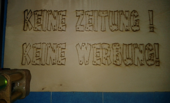
The result is pretty constant color with most small details visible. Only the turningpoints are a bit darker.
Edited 1 time(s). Last edit at 03/17/2017 07:23AM by o_lampe.
So I had to edit the file to fake extruder data, which then triggers the M571 pin.
I had two different F-values for engraving and travel, so I could search & replace F1999 with E0.001 F2000 as seen below.
It seems, there is a minimum extrusion threshold, because I had to raise M92 E-steps until the LD started.
The lines in red are the parameters needed to prepare RRF for laser engraving.
;
G21; Set units to millimeters
G90; Use absolute coordinates
G92; Coordinate Offset

M83 				; Set extrusion to relative
M208 E15000:15000	; raise max. E speed
M302 P1			; allow cold extrusions
M567 P0 E1.0:0.0		; set mixing ratio (for multiple hotend only)
M568 P0 S1			; mixing on
T0				; select tool 0
M42 P66 S0			; set P66 as output
M571 P66 S1.0 F500	; trigger Pin 66 when extrusion happens

M92 E1000:1000			; set extrusion-steps/mm

G00 X134.3 Y13.7 F2000

G01 X134.0 Y13.7 E0.001 F2000

G00 X128.0 Y13.7 F2000

G01 X127.0 Y13.7 E0.001 F2000
The result is pretty constant color with most small details visible. Only the turningpoints are a bit darker.
Edited 1 time(s). Last edit at 03/17/2017 07:23AM by o_lampe.
|
Re: How do I use extruder step signals for Diode-engraving? March 17, 2017 12:45PM |
Registered: 11 years ago Posts: 1,049 |
|
Re: How do I use extruder step signals for Diode-engraving? March 17, 2017 04:29PM |
Admin Registered: 16 years ago Posts: 13,886 |
... I'm importing different vector-formats with selfprogrammed "plugins" to create the needed G-code for my pastedispensers and laserengravers when running them with the Pronterface-variant "gieCAPS".
Previously set in the Marlin4Due-firmware the "E-steps per mm" value to 1, so I can calculate the pulses per line-length as millimeters and multiplicate them with the wished amount of "pulses per mm" to get the absolute pulses.
My "laser-G-Code" looks like:
G0 X6.275 Y200 Z0 F6000
G1 X193.675 Y200 Z0 E937 F6000
G1 X194.95 Y199.875 Z0 E943.405 F6000
G1 X196.125 Y199.5 Z0 E949.57 F6000
G1 X197.2 Y198.925 Z0 E955.665 F6000
G1 X198.125 Y198.15 Z0 E961.7 F6000
G1 X198.9 Y197.225 Z0 E967.735 F6000
G1 ...
The E-value is rounded to INT, as it's the real amount of processed pulses ...
Viktor
--------
Aufruf zum Projekt "Müll-freie Meere" - [reprap.org] -- Deutsche Facebook-Gruppe - [www.facebook.com]
Call for the project "garbage-free seas" - [reprap.org]
|
Re: How do I use extruder step signals for Diode-engraving? March 25, 2017 10:57AM |
Registered: 9 years ago Posts: 11 |
I like this idea very very much. I would suggst to extend it for grayscale images.
First idea:
For this one needs to modify the "Extrusion" to the intensity of the grayscale image. I have never tried to 3D print in multicolor, especially not with a mixing extruder ( [www.reprap.org] , [reprap.org] ). However, I think this could be an "easy" way to for grayscale laser burning.
In my rumbaboard I can connect 3 extruders. I would try to use Extruder0 (E0) for normal printing. When using the Laser engraving I would switch to a mixing extruder. I would connect the Laser to Extruder1 (E1) and nothing to Extruder 2(E2).
In the color palette I would set E0 always to 0. E1 and E2 would mix the grayscale.
Using this one needs only a color coded object (my next task to find out how it works) and could burn images with the laser. When building the 3D model, one has to make a layer as thick as the first layer. One can use all the firmware acceleration / decelleration stuff and the advantages of the slicer options, like different fill pattern (horizontal/ vertical lines, contours, ...).
Does anyone think there is a better way? I do see the problem with the color information in Cura, which is yet my preferred Slicer.
The second idea:
Remove the extrusion driver and connect the laser only, no color mixing options enabled (like done in this thread). Skip all the color information in the first step, slice the first layer and correct the intensity / extrusion by comparing each path with an image. If there is a change in color, the path is cut into several pieces with their own extrusion. For example a move from black to white will be cut into 16 moves if there are 16 colors available.
Or is there an option to change the amount of extrusion within one line segment? This would be something like "always extrude" and one changes for each segment the feedrate of extrusion. The disatvantage of this is, that I would need to write a programm. The first method needs no additional programm, just the knowledge of multicolor prints.
Shall I open a new thread for that?
|
Re: How do I use extruder step signals for Diode-engraving? March 25, 2017 01:15PM |
Admin Registered: 16 years ago Posts: 13,886 |
... I was testing with different "colors" too, which will generate lines and hatching with different pulse-rates and burning amount per colour.
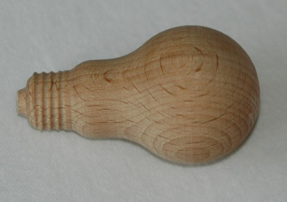
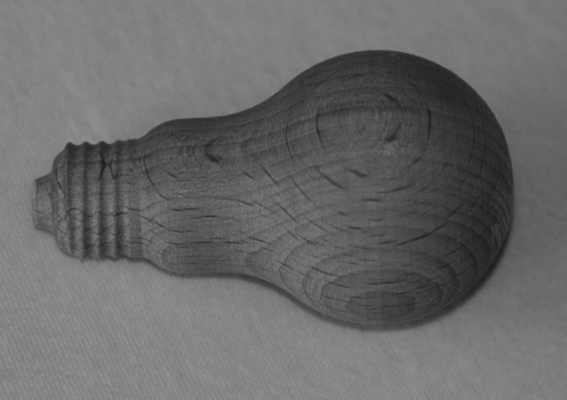
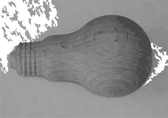
This could be as simple, as converting a color image to greyscale and then vectorize with Corel X6 with set amount of wished shades (here 24):
With my drivers and modified Pronterface it's no problem to redefine the tool-changing for 24 tools (T0 to T23) with adjustuíng the laser power at tool-change and then engrave the lines of the specific colours/tools.
But could be simpler/faster with dithering the image to a pure pixel-representation - my driver has 0.0025mm pixel distance, so won't be much of visible difference to a "real" grey shaded analogue engraving ...
Viktor
--------
Aufruf zum Projekt "Müll-freie Meere" - [reprap.org] -- Deutsche Facebook-Gruppe - [www.facebook.com]
Call for the project "garbage-free seas" - [reprap.org]
|
Re: How do I use extruder step signals for Diode-engraving? April 01, 2017 04:31PM |
Registered: 9 years ago Posts: 11 |
That way to define different tools sound reasonable and good. I just defined a second extruder where I connected my laser to th step signal.
As expected is is normally off. When I move the extruder (extrude) light goes on. The problem ist, that ven though I have set extrusion rate to F6000 and 999 steps/mm, still the power is too low. I tried to increase the "Delay stepper high signal" to 5 µs to increase the on-time, but it did not help. Any suggestions?
edit: tsting blue 2 W 450 nm laser on wood. Works well when always on. No "burning" / engraving when used as described above.
Edited 1 time(s). Last edit at 04/01/2017 04:33PM by karl.ranseier.
|
Re: How do I use extruder step signals for Diode-engraving? April 01, 2017 05:56PM |
Admin Registered: 16 years ago Posts: 13,886 |
... the "effective" power is the sum of ON and OFF times - if the pauses are too long, then 5µs won't be enough to engrave ... especially, when a slow "rising edge" of the signal (what's normal with common drivers) will reduce the ON-time too ...
Viktor
--------
Aufruf zum Projekt "Müll-freie Meere" - [reprap.org] -- Deutsche Facebook-Gruppe - [www.facebook.com]
Call for the project "garbage-free seas" - [reprap.org]
Viktor
--------
Aufruf zum Projekt "Müll-freie Meere" - [reprap.org] -- Deutsche Facebook-Gruppe - [www.facebook.com]
Call for the project "garbage-free seas" - [reprap.org]
Sorry, only registered users may post in this forum.


