laser TTL arduino DUE RADDS 3.3v pinout
Posted by sz3bbylA
|
laser TTL arduino DUE RADDS 3.3v pinout January 10, 2019 04:27PM |
Registered: 7 years ago Posts: 11 |
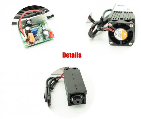
I just bought this laser from aliexpress
is a 2 W laser
I connected to my radds on fan pin 2 and used with commands M106 P1 Sxxx on, and M107 P1 off
is working
but i want to try TTL
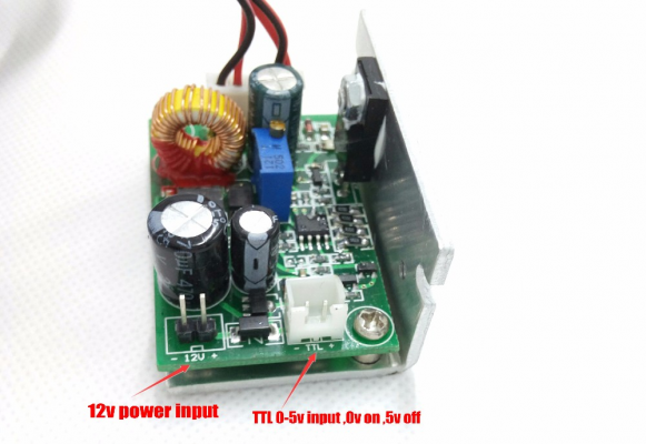
controller for this board is
the problem is I use RADDS with arduino due and pinout are on 3.3 v
I try to figure out how to use it with my board true TTL
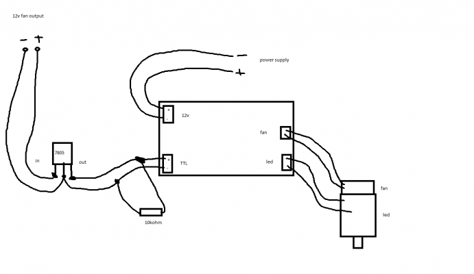
I am not sure but i try to draw a small schematic using normal way to connect a laser true ramps or arduino uno which have 5 v out pins
power supply is that given with laser 12v 5A and is separate by RADDS controller
laser controller can be put on by power supply , I tried also to supply power straight from 12 v Fan , is working but I don't have laser intensity
For PWM --- M106 P1 S1 for example laser already cut paper
idea is to have laser intensity variable
M106 Sxxx is for fan 1
M106 P1 Sxxx is for fan 2
this is happend for REPETIER firmware
maybe somebody can give me some information's in this way
Edited 1 time(s). Last edit at 01/10/2019 04:43PM by sz3bbylA.
|
Re: laser TTL arduino DUE RADDS 3.3v pinout January 10, 2019 06:30PM |
Registered: 9 years ago Posts: 978 |
I'm not an electronics expert, so hopefully someone knowledgable will jump in to confirm/deny my thoughts.
I don't think that a 7805 power regulator would switch fast enough to handle the PWM of the fan speed.
I think if you put a diode and resistor between the 12V out from the fan and 5V on the TTL supply, you could clamp the signal level to 0-5V.
But you should be able to get 0-3.3V by taking the signal from the input to the fan control MOSFET. That may be enough to switch the TTL circuitry of the laser driver. If not, you could use a 3.3V to 5V level converter e.g. [www.aliexpress.com] You can also do it with just a single FET IC: [www.aliexpress.com]
|
Re: laser TTL arduino DUE RADDS 3.3v pinout January 10, 2019 06:33PM |
Admin Registered: 16 years ago Posts: 13,886 |
... "Chinese" TTL is not really defined, so could be other working voltage levels beside +5V too 
If the "TTL"-input didn't have a pullup to +5V or higher (the measured voltage between GND and TTL-In should be 0V), then you can try, if +3,3V will switch the laser OFF.
If yes, then measure the drawn current, if it can work with the RADDS pins directly ...
Viktor
--------
Aufruf zum Projekt "Müll-freie Meere" - [reprap.org] -- Deutsche Facebook-Gruppe - [www.facebook.com]
Call for the project "garbage-free seas" - [reprap.org]
|
Re: laser TTL arduino DUE RADDS 3.3v pinout January 11, 2019 05:54PM |
Registered: 7 years ago Posts: 11 |
I wired straight from pin fan arduino and is working
I'm not sure if must use that resistor 10k
now is working without that resistor but I would like to know why some people are use it
for different materials i use a dimmer to control power intensity and also still in testing trying to print images
so i have variable intensity 0 to 255
also variable power true laser from dimmer
maybe somebody know why people use that resistor 10k TTL- to TTL+
Sorry, only registered users may post in this forum.


