Anti-ooze nozzle
Posted by Lampbus
|
Anti-ooze nozzle July 04, 2008 07:08AM |
Registered: 15 years ago Posts: 78 |
I have seen the solenoid driven pin valve design to prevent nozzle ooze, but how about a completely passive system - have a spring loaded valve in the nozzle ?
It would need tome experimentation to set the spring opening pressure so that gravity and thermal expansion and residual pressure due to 'springyness' of system components is balanced.
And then, tuning so that it dosnt put excessive back-pressure on the drive.
I was originally thinking of a tiny spring and valve plate in the nozzle itsself, but i have just thought that it could be actuated by the vertical loading of the filament into the heater barrel. THis would drive the heater/nozzle assembly down a fraction and the nozzle valve pin would be withdrawn. It would help if the pin was as close to co-axial with the heater.
The filament may need 'backing up' a fraction to ensure sharp close off.
|
Re: Anti-ooze nozzle July 04, 2008 08:36AM |
Registered: 15 years ago Posts: 100 |
I like the idea of less parts, but I'm having trouble imagining how the pin would be mounted.
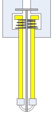
I've done a little diagram of what I came up with, but it involves putting the pin holder above the heater. I can't see that working as the plastic is still solid there.
Also how would we insure that the barrel moved to the same height each time?
Thanks in advance,
Pete
I've done a little diagram of what I came up with, but it involves putting the pin holder above the heater. I can't see that working as the plastic is still solid there.
Also how would we insure that the barrel moved to the same height each time?
Thanks in advance,
Pete
|
Re: Anti-ooze nozzle July 04, 2008 12:15PM |
Registered: 15 years ago Posts: 78 |
Nice diagram Peteredworthy.
You inspire me to get doodling
It would be nice to put the pin inside as you show, but as you say, the plastic is solid at some point in the insulator so gets in the way.
THe spring would only be stiff enough to support the weight of the heater/insulator and liquid contents and to overcome any friction in the mount/valve pin. The pressure from the pushing filament is X.
Does anyone have a value for the barrel pressure ?
My diagrams are attached.
|
Re: Anti-ooze nozzle July 04, 2008 02:14PM |
Registered: 15 years ago Posts: 78 |
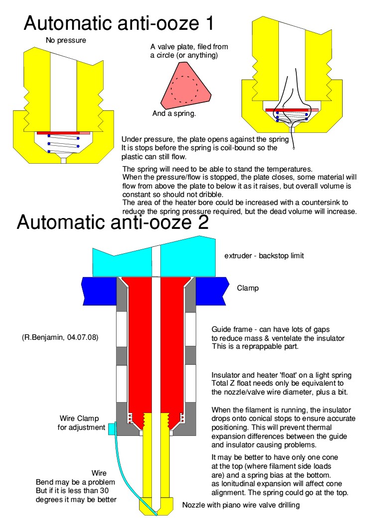
And another idea :
Have a fixed insulator&heater like current design, but allow the extruder drive bracket to float UP a milimeter with the vlave wire connected to it.
As the filament is fed, the motor/clamp raises slightly it opens the valve.
Gravity and a spring will push it back down.
To keep the valve wire short to prevent it buckling on closeure, an actuator rod could be used. THis would have a flexible joint at each end and would thus be self-aligning (if you see what I mean)
|
Re: Anti-ooze nozzle July 04, 2008 02:54PM |
Registered: 16 years ago Posts: 370 |
|
Re: Anti-ooze nozzle July 04, 2008 03:39PM |
Registered: 15 years ago Posts: 78 |
Kyle Corbitt Wrote:
-------------------------------------------------------
> Richard, I especially like your first concept. It
> has the potential to be effective without
> substantially increasing the complexity of the
> extruder. It's almost a drop-in addition to the
> current design. Props.
THats what I thought
Problem is it will have a pressure drop across it which will contribute to the overall extruder motor loading. Also, I dont know how much ooze will occur from the spring area. It needs to be kept as compact as pos in there whilst still allowing a low friction path for flowing material.
(I sometimes design valves for a living, my latest at www.charltonco.uk.com)
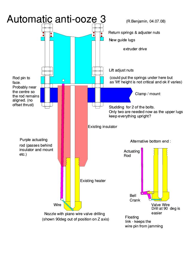
Option 3 is attached.
This is even easier to adapt from existing parts
The bell crank can be made unequal so that only say 0.25mm lift is required at the rod/drive assembly to withdraw the pin 1mm. THere is plenty of power available for this, but slack in the pins will be a problem (im thinking of reprap precision, not instrument bearings)
THe floating link could be eliminated if the bell crank has a large enough radius and the wire pin is flexible and/or the pin drilling is not needed to be a good fit. THe link is on the wrong axis to be a good engineering solution. It is also extra complication.
Please give it a go someone, my repstrap is still in bits - some of which are currently mid Atlantic - hurry up parcel farce.
Edited 1 time(s). Last edit at 07/04/2008 03:54PM by Richard Benjamin.
-------------------------------------------------------
> Richard, I especially like your first concept. It
> has the potential to be effective without
> substantially increasing the complexity of the
> extruder. It's almost a drop-in addition to the
> current design. Props.
THats what I thought
Problem is it will have a pressure drop across it which will contribute to the overall extruder motor loading. Also, I dont know how much ooze will occur from the spring area. It needs to be kept as compact as pos in there whilst still allowing a low friction path for flowing material.
(I sometimes design valves for a living, my latest at www.charltonco.uk.com)
Option 3 is attached.
This is even easier to adapt from existing parts
The bell crank can be made unequal so that only say 0.25mm lift is required at the rod/drive assembly to withdraw the pin 1mm. THere is plenty of power available for this, but slack in the pins will be a problem (im thinking of reprap precision, not instrument bearings)
THe floating link could be eliminated if the bell crank has a large enough radius and the wire pin is flexible and/or the pin drilling is not needed to be a good fit. THe link is on the wrong axis to be a good engineering solution. It is also extra complication.
Please give it a go someone, my repstrap is still in bits - some of which are currently mid Atlantic - hurry up parcel farce.
Edited 1 time(s). Last edit at 07/04/2008 03:54PM by Richard Benjamin.
|
Re: Anti-ooze nozzle July 04, 2008 04:18PM |
Admin Registered: 16 years ago Posts: 13,884 |
... main problem could be clogging of the valve with material in the feeding - you need much force to pierce a needle through a plastic-filled hole ...
For a simple valve-mechanic you can use a heated nitinol-wire as actuator against a strong spring. It's the simplest method for applying high forces when you can drive the current.
Viktor
For a simple valve-mechanic you can use a heated nitinol-wire as actuator against a strong spring. It's the simplest method for applying high forces when you can drive the current.
Viktor
|
Re: Anti-ooze nozzle July 04, 2008 05:38PM |
Registered: 15 years ago Posts: 78 |
Viktor, I am basing my ideas on : [blog.reprap.org]
and the assumption that the tip of the nozzle contains fluid plastic due to being very close to the heater. This will also mean the cross-drilling dosn't have to be very precise or have seals. Seals are also a reason I avoided a sliding nozzle or heater (see peteredworthy's sketch) and slid the whole heater/insulator assembly in option 2. there isnt any molton plastic to seal at the top of the insulator.
Actually, if it were possible to heat/cool a small part of the final narrow nozzle independently from the main heater, that could be an effective valve. Unlikely to be fast enough though.
|
Re: Anti-ooze nozzle July 05, 2008 03:13AM |
Registered: 16 years ago Posts: 146 |
I think Richard's "AntiOoze3.jpg" alternative is a good idea. I can't see how to move it up/down to affect the pressure in the nozzle.
The other spring ideas are good, but it would be too hard to get the right tension spring to get enough pressure in there to stop the flow when needed, but not hinder the regular usage.
Sorry for using your image Richard, but it was easier adding to it than making a new one.
My idea uses a pawl system utilizing the current motor for the filament feeder. This way, one motor, and full control over pressure.
There is no need to reverse the motor on the GM motor except when you want less pressure in the extruder, and at the same time you could use that reverse motion to lock the nozzle with a good ammount of pressure. When the motor goes forward, it doesn't do anything to the blocking wire, when it's reversed slightly it will use the pawl gear to push the rod down blocking the extruder head. When it goes forward again a spring would push the rod back up releasing the wire to a neutral position.
Animation should help:
(Of course, it's just a sketch at the moment. placement of gears and sizes in comparison to where the GM is and it's angle will need some tweaks)
The other spring ideas are good, but it would be too hard to get the right tension spring to get enough pressure in there to stop the flow when needed, but not hinder the regular usage.
Sorry for using your image Richard, but it was easier adding to it than making a new one.
My idea uses a pawl system utilizing the current motor for the filament feeder. This way, one motor, and full control over pressure.
There is no need to reverse the motor on the GM motor except when you want less pressure in the extruder, and at the same time you could use that reverse motion to lock the nozzle with a good ammount of pressure. When the motor goes forward, it doesn't do anything to the blocking wire, when it's reversed slightly it will use the pawl gear to push the rod down blocking the extruder head. When it goes forward again a spring would push the rod back up releasing the wire to a neutral position.
Animation should help:

(Of course, it's just a sketch at the moment. placement of gears and sizes in comparison to where the GM is and it's angle will need some tweaks)
|
Re: Anti-ooze nozzle July 05, 2008 05:50AM |
Registered: 15 years ago Posts: 78 |
Dylan - the animation is cool
But in my Antiooze3 the nozzle valve is controlled (almost) directly by the melted plastic pressure as follows :
As the extruder motor starts to feed filament into the heater, the pin valve is closed so pressure builds. Instead of filament feeding into the heater, the motor & its mounting do an Indian rope trick and climb the filament a teeny bit. This upward movement pulls on the rod, cranks the crank and opens the valve. Plastic flows.
When its time to stop, the extruder motor reverses a teeny bit, climbing back down the filament and dropping the whole assembly with the help of the springs. Rod pushes, valve closes.
If the motor stops without backing up, a small ammount will ooze until the pressure drops and the valve still closes.
|
Re: Anti-ooze nozzle July 05, 2008 12:18PM |
Registered: 16 years ago Posts: 146 |
OK, that explains it a little more for me. But that's close to what I was thinking. You'd still have to do what I mentioned about making sure you have just the right amount tention back off as needed and open as needed.
It would defenitely be less complicated to build, especially since the current head design has the 2 part top/bottom already.
I guess the only way we'll see which of all these ideas will work best it to build them. Unfortunately I don't have a machine shop to drill the holes into the nozzle.
It would defenitely be less complicated to build, especially since the current head design has the 2 part top/bottom already.
I guess the only way we'll see which of all these ideas will work best it to build them. Unfortunately I don't have a machine shop to drill the holes into the nozzle.
|
Re: Anti-ooze nozzle July 16, 2008 06:20PM |
Registered: 17 years ago Posts: 550 |
Hi,
let me push that one with a suggestion:
I held my honeybottle in my hands today and wondered if those non-dripping siliconelips could be useful for this purpose.
For those who wonder what I mean:
[www.wpiberica.com]
I unfortunately don't have any extruder to give it a test,
is anyone out there that could give it a try?
'sid
|
Re: Anti-ooze nozzle July 17, 2008 08:04AM |
Registered: 16 years ago Posts: 361 |
|
Re: Anti-ooze nozzle July 17, 2008 10:54AM |
Registered: 15 years ago Posts: 78 |
|
Re: Anti-ooze nozzle July 17, 2008 04:20PM |
Registered: 16 years ago Posts: 370 |
|
Re: Anti-ooze nozzle July 17, 2008 05:52PM |
Registered: 16 years ago Posts: 361 |
Quote
Anyone know a good source for these silicon pieces?
I imagine you could make one, given a suitable slice of silicone. They don't look like precision instruments.
Quote
I'm worried that if it's too thick it will make extruding unpredictable
That sounds like a much more sensible argument against them. From careful study of sauce dynamics, I'd say you might have to worry about a buildup of pressure behind the seal before it gives way, causing a short spurt of molten plastic.
|
Re: Anti-ooze nozzle July 17, 2008 05:55PM |
Registered: 17 years ago Posts: 550 |
Hi Kyle,
mainly there are two different versions of the valve, slit and cross-slitted,
I think cross-slitted may be more accurate (i would imagine so)
The easiest source for these valves is to salvage them from an empty bottle of...
Honey, bodymilk, ketchup and so forth.
If you find a honeybottle standing cap down in the supermarket it's almost sure that you'll find such silicone valve in it
If you keep a look at the link I posted above you see the complete cap.
Alomost everywhere I've been I found Honey with exactly this cap.
'sid
I do have some almost empty bottles but I'd guess shipping is more expensive then a bottle of honey in your local store
|
Re: Anti-ooze nozzle August 20, 2008 07:37AM |
Registered: 15 years ago Posts: 6 |
A question from a new member regarding the use of a valve for controlling the ooze issue. Has anyone looked into the use of a mini brass ball valve? They seem to be available with an 1/8" port (close to 3mm). The only real issue I see would be the temperature rating. They are rated at about 180 celsius. However, that is probably due to the valve seat material. As a water-tight seal is not required it may be possible to remove or "burn off" the plastic valve seat material, leaving just the brass body and valve.
|
Re: Anti-ooze nozzle August 20, 2008 01:29PM |
Registered: 16 years ago Posts: 370 |
No, I don't think anyone has tried it but interesting idea. The ball valve would have to be very close to the actual extruding location though, I would think, for it to be effective.
I would think that a water-tight seal would be necessary. While molten plastic is (apparently) much more viscous than water or most other liquids, it will also be at relatively high pressures, so if there are cracks or gaps I could imagine it being forced into them. Anyone with more experience want to chime in?
I would think that a water-tight seal would be necessary. While molten plastic is (apparently) much more viscous than water or most other liquids, it will also be at relatively high pressures, so if there are cracks or gaps I could imagine it being forced into them. Anyone with more experience want to chime in?
|
Re: Anti-ooze nozzle August 20, 2008 05:35PM |
Registered: 15 years ago Posts: 6 |
Teflon seated brass steam valves are often rated at 400F (200C). First random example I found:
[www1.mscdirect.com]
At that temperature you may not get the max 150psi steam pressure. Anyone know what pressures can be expected at the extruder head?
[www1.mscdirect.com]
At that temperature you may not get the max 150psi steam pressure. Anyone know what pressures can be expected at the extruder head?
|
Re: Anti-ooze nozzle August 20, 2008 06:25PM |
Registered: 16 years ago Posts: 370 |
I know there was a thread here some weeks ago where we discussed internal pressures and came up with a number, but I can't seem to find it now! I'll post back if I run across it.
EDIT: Found it. In his first post in the thread at [forums.reprap.org], Forrest estimated that the internal pressure is in the 17-18 bar ballpark.
RE-EDIT: Looks like forrest beat me to it.
Edited 2 time(s). Last edit at 08/20/2008 06:32PM by Kyle Corbitt.
EDIT: Found it. In his first post in the thread at [forums.reprap.org], Forrest estimated that the internal pressure is in the 17-18 bar ballpark.
RE-EDIT: Looks like forrest beat me to it.
Edited 2 time(s). Last edit at 08/20/2008 06:32PM by Kyle Corbitt.
|
Re: Anti-ooze nozzle August 20, 2008 06:29PM |
Admin Registered: 17 years ago Posts: 1,915 |
Kyle Corbitt Wrote:
-------------------------------------------------------
> I know there was a thread here some weeks ago
> where we discussed internal pressures and came up
> with a number, but I can't seem to find it now!
> I'll post back if I run across it.
>
17-18 bar
[forums.reprap.org]
-------------------------------------------------------
> I know there was a thread here some weeks ago
> where we discussed internal pressures and came up
> with a number, but I can't seem to find it now!
> I'll post back if I run across it.
>
17-18 bar
[forums.reprap.org]
|
Re: Anti-ooze nozzle August 21, 2008 07:22AM |
Registered: 15 years ago Posts: 6 |
It looks like the vavle specifications are as follows:
Brass or Bronze for thermal transfer
3mm port (1/8")
18 bar at 200 or 300C (260psi at 400 to 572F)
Right about now the piano wire method is looking pretty good! Not impossible, but certainly much more expensive than the $10.00 one I posted earlier. The biggest issues will be port size and material. Most high-pressure steam valves start at 1/4" and are stainless steel (not the best material to transfer heat). While these temperatures and pressures are a lot more than what we specify where I work, I will look at our Plumbing/HVAC catalogs and see if anything jumps out. I work on the electrical side of building engineering, so I do not have a lot of experience with valves.
|
Re: Anti-ooze nozzle August 21, 2008 08:53AM |
Admin Registered: 17 years ago Posts: 7,879 |
|
Re: Anti-ooze nozzle August 21, 2008 01:03PM |
Registered: 15 years ago Posts: 6 |
I was thinking that the valve would be located between the 3mm bore and the nozzle. It would not completely stop the issue (as there would be a small quantity of plastic between the valve and nozzle), but should reduce it to managable level. However, in looking at the valve manufacturer's catalogs a valve rated for the required temperature and pressure would be quite large and probably very expensive.
Although I wonder if the pressure rating needs to be 18 bar, as the extruder drive would be stopped prior to shutting the valve.
Although I wonder if the pressure rating needs to be 18 bar, as the extruder drive would be stopped prior to shutting the valve.
|
Re: Anti-ooze nozzle August 21, 2008 01:54PM |
Admin Registered: 17 years ago Posts: 7,879 |
I think closing a valve of that size would displace a significant amount of plastic. We can stop the flow by reversing the motor but even if the flow stops it is still connected to the object and moving the head will drag out molten plastic. We need a valve right at the end of the nozzle so it cuts the filament as close to the object as possible.
[www.hydraraptor.blogspot.com]
[www.hydraraptor.blogspot.com]
|
Re: Anti-ooze nozzle August 21, 2008 02:51PM |
Registered: 16 years ago Posts: 123 |
|
Re: Anti-ooze nozzle August 21, 2008 02:55PM |
Admin Registered: 16 years ago Posts: 13,884 |
... imagine the different extrusion methods in nature: - for example the mandibles of wasps or the dispenser-like 'nozzles' of termites and some insects building structures from fluid organic pastes.
With the mandibles it's something like knifes cutting from the sides into the filament and closing the opening.
With the 'nozzles' there should be some elements inside the tube, maybe three thin fibres extruded from feedings to close the nozzle?
Viktor
With the mandibles it's something like knifes cutting from the sides into the filament and closing the opening.
With the 'nozzles' there should be some elements inside the tube, maybe three thin fibres extruded from feedings to close the nozzle?
Viktor
|
Re: Anti-ooze nozzle August 21, 2008 06:03PM |
Registered: 15 years ago Posts: 78 |
The advantage of a ball valve is it dosnt displace material axially as it opens/closes. It just rotates a plug of material through 90 degrees shearing of the flow. 3mm (1/8") would be big, but not massive. So long as the nozzle is screwed directly into the lower thread it could be worth a try. Polymer below the closed valve could still leak though.
They tend to be fairly stiff to operate too (but my experiece is with 1/4" and up) but if the seals are backed off a bit...
They tend to be fairly stiff to operate too (but my experiece is with 1/4" and up) but if the seals are backed off a bit...
|
Re: Anti-ooze nozzle August 22, 2008 08:28PM |
Registered: 15 years ago Posts: 6 |
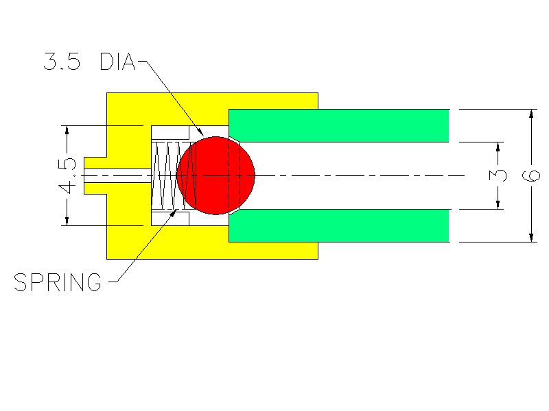
In thinking it through a little further a ball valve may not be the best idea. A valve meeting all the temperature and pressure requirements will be expensive and large. Plus it is an active system requiring additional programming and motor/solenoid. A passive system such as shown by Richard appeals to me. The only thing I would do different is use a small brass or bronze bearing, with three ribs brazed into the cap to keep the movement to just enough to allow the plastic to pass. This will keep the spring from fully compressing and creating a "plug" (something Richard was taking care of with a tapered cap and triangular valve plate).

Sorry, only registered users may post in this forum.