Help with cantilevered printer design
Posted by aEx155
|
Help with cantilevered printer design April 15, 2014 12:08PM |
Registered: 10 years ago Posts: 22 |
Hello, first post here.
I've managed to collect various mechanical pieces over time and I'm approaching the critical point where I have enough to complete a printer. Currently I am trying to create a new design to fit some of the pieces I have:
The outer support frame will be made with the aluminum extrusion. X and Y axes will use GT2, while Z axis will use M8 SS threaded rod.
I'm considering cantilevered designs because it reduces the complexity a bit; is it worth it or do I end up loosing too much stiffness?
For the second design (8mm rod for Z-axis) will 8mm be stiff enough for supporting the bed? Or will I need to upgrade that?
Opinions appreciated. Thanks in advance.
I've managed to collect various mechanical pieces over time and I'm approaching the critical point where I have enough to complete a printer. Currently I am trying to create a new design to fit some of the pieces I have:
- a section IKO LWE15 linear rail
- matching LWE15 linear bearing
- 15mm aluminum extrusion
- four 300mm * 8mm SS smooth rod
- LM8UU linear bearings


The outer support frame will be made with the aluminum extrusion. X and Y axes will use GT2, while Z axis will use M8 SS threaded rod.
I'm considering cantilevered designs because it reduces the complexity a bit; is it worth it or do I end up loosing too much stiffness?
For the second design (8mm rod for Z-axis) will 8mm be stiff enough for supporting the bed? Or will I need to upgrade that?
Opinions appreciated. Thanks in advance.
|
Re: Help with cantilevered printer design April 15, 2014 12:40PM |
Registered: 11 years ago Posts: 1,049 |
Perhaps you should make it a REAL cantilever
by extending the rail out the back with a weight
to equal the arm weight?
Doesn't look very rigid. Need more structure to support arm
so it doesn't droop and screw up Z
and doesn't swing around screwing up X Y
Really -- your arm is going to hold up 5 pounds of extruder?
Right now design might have +- 1 inch resolution???
|
Re: Help with cantilevered printer design April 15, 2014 01:22PM |
Registered: 10 years ago Posts: 869 |
|
Re: Help with cantilevered printer design April 15, 2014 02:20PM |
Registered: 10 years ago Posts: 22 |
Quote
cozmicray
Really -- your arm is going to hold up 5 pounds of extruder?
[www.ikont.com] < linear rail datasheet
According to the datasheet I can go up to 56 pounds, actually
 . I was planning on using a Bowden-style extruder setup anyways, to reduce stress on the arm.
Here is a test piece I printed at my library's Replicator 2:

Correct me if I'm wrong, but I believe I can use the stiffness provided by the linear rail system assuming I can affix the X-axis rods to the Y-carriage bearing well enough.
I modified the Y-axis carriage to include a motor mount for the X-axis and help balance things. That will probably have to change though because I don't know how the belt will fit in.

|
Re: Help with cantilevered printer design April 16, 2014 12:46AM |
Registered: 11 years ago Posts: 979 |
I think the cantilever setup will leave the system very springy. That is not a deal breaker. You will just have to reduce the speed and acceleration settings.
I would go with Fi30oFF.png. That setup doesn't have any major dynamic forces that would cause the cantilevered arm spring back and forth. I think the rest of your mockups do.
ConceptFORGE
Wally, GUS Simpson, LISA Simpson, THOR Simpson, Sextupteron, CoreXZ
I would go with Fi30oFF.png. That setup doesn't have any major dynamic forces that would cause the cantilevered arm spring back and forth. I think the rest of your mockups do.
ConceptFORGE
Wally, GUS Simpson, LISA Simpson, THOR Simpson, Sextupteron, CoreXZ
|
Re: Help with cantilevered printer design April 16, 2014 11:36AM |
Registered: 10 years ago Posts: 22 |

I've reworked the design to move the linear rail to the bottom to serve as the Y-axis, because it's the heaviest axis (in terms of the linear rail mass). I also reduced the X-axis travel to 150mm for two reasons: 1) because it's the cantilevered axis and 2) my 300mm rods don't have enough length to support 200mm of travel; a method of affixing the X-axis rods to the Z-carriage hasn't been modeled. The X-axis motor and potentially the bowden-extruder will be mounted opposite the bed on the X-axis rods as counterbalance.
Is this a better route?
|
Re: Help with cantilevered printer design April 16, 2014 11:51AM |
Registered: 11 years ago Posts: 979 |
Perfect. I would have at least a 50mm long sleeve for your cantilever rods to stick through. BTW, why not also cantilever a support out to make your free end more rigid? (I will model something when I get a chance.). Also make sure your z linear bearings cover a 75mm span in the z direction if you want smooth chatter free motion.
ConceptFORGE
Wally, GUS Simpson, LISA Simpson, THOR Simpson, Sextupteron, CoreXZ
ConceptFORGE
Wally, GUS Simpson, LISA Simpson, THOR Simpson, Sextupteron, CoreXZ
|
Re: Help with cantilevered printer design April 16, 2014 04:51PM |
Registered: 10 years ago Posts: 22 |

Here is my most recent iteration for the Z-carriage. The Z-bearings span 75mm and there is 50mm of support for the X-axis, as suggested. The cantilever will extend away from the bed, and the X-axis motor will mount beyond that.
The linear bearings for the Z-axis are currently designed to be held on by zip-ties because that was easiest, though I'm unsure if it will be strong enough. I'm also working on a redesign to try and reduce the printing time from 3 hours (the limit for free prints at the library is 2 hours).
|
Re: Help with cantilevered printer design April 16, 2014 04:58PM |
Registered: 10 years ago Posts: 1,381 |
Per Du7pLaI.png pic, rotate your X and Z axis 90 degrees.
You want an I-beam configuration on your X axis, (like in this pic Fi30oFF.png).
Rotating the Z axis 90 degrees will increase the moment rigidity of the X axis, and it will allow you to add a 3rd bearing to the X axis to increase rigidity.
Edited 1 time(s). Last edit at 04/16/2014 04:59PM by A2.
You want an I-beam configuration on your X axis, (like in this pic Fi30oFF.png).
Rotating the Z axis 90 degrees will increase the moment rigidity of the X axis, and it will allow you to add a 3rd bearing to the X axis to increase rigidity.
Edited 1 time(s). Last edit at 04/16/2014 04:59PM by A2.
|
Re: Help with cantilevered printer design April 16, 2014 05:53PM |
Registered: 10 years ago Posts: 22 |
Quote
A2
Per Du7pLaI.png pic, rotate your X and Z axis 90 degrees.
You want an I-beam configuration on your X axis, (like in this pic Fi30oFF.png).
Rotating the Z axis 90 degrees will increase the moment rigidity of the X axis, and it will allow you to add a 3rd bearing to the X axis to increase rigidity.
Is this what you meant?

This simplifies the Z-carriage signifigantly. I regret only ordering 300mm smooth rod, though, because I'm limited on carriage size and mounting options. The current build volume is 150 x 200 x 200 mm^3 and that's stretching things a bit.
|
Re: Help with cantilevered printer design April 16, 2014 07:59PM |
Registered: 10 years ago Posts: 1,381 |
|
Re: Help with cantilevered printer design April 17, 2014 01:11AM |
Registered: 10 years ago Posts: 22 |
Quote
A2
That's correct.
Adding a 3rd bearing to the X, and Y axes would be an improvement.
Why only one linear slide on the Y axis?
You can also increase the spacing between the linear slides on all axes to increase rigidity, but you are limited by your build volume.
I only have one linear slide for the Y-axis because I only have one and I don't know where to buy another one...
The X-axis carriage isn't shown but I was already planning on having 3 bearings; I figured a moving carriage would be less mass than moving the rods (Printrbot simple or Smartrap)
|
Re: Help with cantilevered printer design April 17, 2014 02:00AM |
Registered: 10 years ago Posts: 1,381 |
Quote
aEx155
I figured a moving carriage would be less mass than moving the rods (Printrbot simple or Smartrap)
Ok I like that idea, I made the assumption that the X axis linear rods were moving.
Separate the Z axis linear guides as much as possible.
For the Y axis second rail it's a follower, meaning all it has to do is support a cantilevered mass.
So you can use a ground rod with a simple plain bearing riding on top of it.
If you lack the resources, you could use a piece of glass leveled, and parallel to the Y axis as a support and guide.
|
Re: Help with cantilevered printer design April 17, 2014 02:11AM |
Registered: 10 years ago Posts: 22 |
Quote
A2
For the Y axis second rail it's a follower, meaning all it has to do is support a cantilevered mass.
The bed is centered on top of the Y-axis bearing, so it's not cantilevered, which is why I thought to just use one bearing. Also, the load capacity of the linear rail is many times more than what it will ever see so I'm assuming it will work fine by itself.
Edited 1 time(s). Last edit at 04/17/2014 02:12AM by aEx155.
|
Re: Help with cantilevered printer design April 17, 2014 02:54AM |
Registered: 10 years ago Posts: 1,381 |
The width of the rail is 15 mm x 14.5 mm (0.590 in x 0.570 in) which is on the small side.
I'm guessing (I don't have data to reference) that the the bearing preload to achieve 56 pounds would be greater than the precision preload that is being quoted, i.e. really tight.
If this is the case, then the force to move the carriage is going to more.
I couldn't find a preload chart in the link you provided, so I really don't know.
The chart did indicate that the moment is a static moment (To), not dynamic.
In addition you need to calculate what the maximum load would be that is greater than 1.0 inch from the carriage center.
The further away you move away from the center of the bearing the less the weight that can be supported.
I'm guessing again that the printer carriage, and the mass that it's going to support is not much,
and I don't think this is worth worrying about, but it's some thing to consider if the carriage does end up supporting a lot of weight.
I did find this in your link.
For applicable combinations of accuracy and preload amount, see Table 2. For details of preload amount, see page 84.
[www.ikont.com]
I think you can get away with one rail, but it's better to have two.
Edited 1 time(s). Last edit at 04/17/2014 03:05AM by A2.
|
Re: Help with cantilevered printer design April 17, 2014 05:15AM |
Registered: 10 years ago Posts: 22 |
Quote
A2
I think you can get away with one rail, but it's better to have two.
[www.makergear.com]
The printer linked above uses single rails and bearings for the X and Y axes. I can't verify that the linear rails used by this printer are the same as the one I have, but they seem to get by using only one rail and carriage.
Obviously two rails would be better, but I'll go ahead with the single rail, and if there are issues, I'll supplement it with another rod and bearing.
Edited 1 time(s). Last edit at 04/17/2014 05:17AM by aEx155.
|
Re: Help with cantilevered printer design April 17, 2014 06:18AM |
Registered: 10 years ago Posts: 1,381 |
|
Re: Help with cantilevered printer design April 17, 2014 01:32PM |
Registered: 10 years ago Posts: 22 |
Quote
A2
The makergear linear bearing looks to be the same size.
Q:
are you copying the MakerGear printer,
are you raising/lowering the Y axis,
are you adding a gantry support,
why are you creating your own design?
I'm going ahead with making my own design because the parts I have currently don't match up with other current designs. I'm not trying to copy any specific printer design (beyond having 3 orthogonal stepper motor driven axes), I'm just trying to make it work with the parts I have. I'm only expecting this to be a one-off design at the moment.
The Y-axis and its linear rail have been moved to the bottom of the printer to be stationery, because of the mass of the linear rail. The MakerGear printer was just an example of another printer using a single linear rail for an axis. At the moment I don't think the frame will be a full gantry-style setup, though I have enough aluminum extrusion to do it.
Here is the latest iteration:


I have been using a Mendel frame triangle for scale, so that's why it's included. The Z-axis rods are 75mm apart, with 75mm of bearing span.
|
Re: Help with cantilevered printer design April 17, 2014 02:23PM |
Registered: 11 years ago Posts: 979 |
I am about to make a suggestion and it won't sound like a smart change but it is. Trust me.
Flip the x rail upside down. Mount the carriage statically and have the rail be dynamic (assuming the rail is light enough). This eliminates edge sag worries by keeping the carriage directly under the cantilever. In theory even if you are at one extreme or the other and the end of the rail is sagging, the height above the carriage will be unaffected.
Additionally, I have concerns about how rigid your frame will be. What do you think about using wood? Is laser cutting an option for you?
ConceptFORGE
Wally, GUS Simpson, LISA Simpson, THOR Simpson, Sextupteron, CoreXZ
|
Re: Help with cantilevered printer design April 17, 2014 03:01PM |
Registered: 10 years ago Posts: 22 |
Quote
nicholas.seward
I am about to make a suggestion and it won't sound like a smart change but it is. Trust me.
Flip the x rail upside down. Mount the carriage statically and have the rail be dynamic (assuming the rail is light enough). This eliminates edge sag worries by keeping the carriage directly under the cantilever. In theory even if you are at one extreme or the other and the end of the rail is sagging, the height above the carriage will be unaffected.
Additionally, I have concerns about how rigid your frame will be. What do you think about using wood? Is laser cutting an option for you?

I'm not sure what you mean by flipping the X-axis upside down; I am using smooth rods for X and Z and the liner rail for the Y.
If you meant the Y axis, I'm worried the mass of the rail will result in too much inertia (the rail is the heaviest mechanical piece at the moment. If you did mean moving the smooth rods of the X axis, I'm keeping the rods static and moving the carriage to increase stiffness and reduce inertia; is that the wrong approach?
As for the frame, I will be using 15x15mm aluminum extrusion (similar to OpenBeam) with either aluminum plates or printed plates for reinforcement, so it should be fairly rigid. Laser cutting is not an option at the moment.
Edited 1 time(s). Last edit at 04/17/2014 03:03PM by aEx155.
|
Re: Help with cantilevered printer design April 17, 2014 03:51PM |
Registered: 11 years ago Posts: 979 |
I meant the y but if it is heavy then forget that suggestion. I have seen rails like that before that were lighter then their carriages.
Looking good!
ConceptFORGE
Wally, GUS Simpson, LISA Simpson, THOR Simpson, Sextupteron, CoreXZ
Looking good!
ConceptFORGE
Wally, GUS Simpson, LISA Simpson, THOR Simpson, Sextupteron, CoreXZ
|
Re: Help with cantilevered printer design April 17, 2014 05:18PM |
Registered: 10 years ago Posts: 1,381 |
A few design ideas to consider:
You only need 3 bearings on the Z axis, triangulate them.
I would prefer a belt on the Z axis, but the stepper might not have enough torque to move the overhanging gantry, you will have to do the math.
The idler pulley on the end of the X axis looks like it's cantilevered out too much, i.e. it might creep over time, reduce the height to a minimum.
The pulley bracket also needs to be redesigned to resist twisting (torsion).
I would align the center of the pulley with one of the metal guides, this will transfer the force to the metal rod.
Radius all the things.
pg15
Bending Stress
Beams in Torsion
[plastics.dupont.com]
pg III-4
Bending Stress
Beams in Torsion
[www2.basf.us]
|
Re: Help with cantilevered printer design April 17, 2014 09:33PM |
Registered: 10 years ago Posts: 22 |
Quote
A2
A few design ideas to consider:
You only need 3 bearings on the Z axis, triangulate them.
I would prefer a belt on the Z axis, but the stepper might not have enough torque to move the overhanging gantry, you will have to do the math.
The idler pulley on the end of the X axis looks like it's cantilevered out too much, i.e. it might creep over time, reduce the height to a minimum.
The pulley bracket also needs to be redesigned to resist twisting (torsion).
I would align the center of the pulley with one of the metal guides, this will transfer the force to the metal rod.
Radius all the things.
I have four bearings for the Z-axis because it simplifies construction; the screws that clamp the Z-bearings also hold down the X-axis rods, so that both are rigidly held together.
Right after I made my last post I started redesigning the X-axis belt and motor placement because I felt they were too far out as well. Here is the latest revision:


The old version is on the left. I also flipped it so the motor would be on towards the back. The X-rod clamp is moved to show the motor placement.

Above are pervious and current versions all the printed parts so far, excluding the X-carriage. The new revision is simpler and more compact which I like. The motor mounts to the X-rod clamps instead of a Z-bearing clamp, and the belt passes on the opposite side of the Z-rods now. I will probably have to modify the X-rod clamp to accommodate the GT2 pulley.
|
Re: Help with cantilevered printer design April 17, 2014 11:22PM |
Registered: 10 years ago Posts: 102 |
|
Re: Help with cantilevered printer design April 17, 2014 11:26PM |
Registered: 10 years ago Posts: 1,381 |
Looks much improved.
Can you show me a top down cross sectional view of the X axis m7s9x0F.png.
It's a bit of an optical illusion for me to visualize the belt, pulley, stepper, Z axis relationships.
More ideas, and note because I can't see how some things relate some suggestions clash.
X axis distal end pulley bracket: I would design it with a bolt passing through two plates on either side of the pulley, as it would help distribute the torsional forces more effectively.
Consider a clam shell configuration.
The stepper motor can be used to increase the rigidity of the Z axis bracket,
by rotating the X axis stepper motor to align all 4 threads with the Z axis brackets.
H-bracket that mounts the X axis linear rods to the Z axis bracket:
The horizontal tie rod is not adding to the structural integrity, it can be deleted.
The width of the H-bracket, I would design it at minimum 3X the diameter of the rod, and change the bolt hole pattern to a diagonal.
Z axis bracket:
I don't like the X axis rod unconstrained, i.e. it's located against a flat surface.
Add a grove, or a raised feature to partially capture the X axis rods.
The grove or raised feature will help to lessen the torsional force on the bolts in the H-bracket.
The stepper motor mounting holes might interfere.
Not seeing how you are going to translate the X axis up and down, makes it hard to know for sure what makes sense.
iterate, iterate, iterate...
|
Re: Help with cantilevered printer design April 18, 2014 12:28AM |
Registered: 10 years ago Posts: 22 |
As requested.
You can see the Z-axis motor in the bottom right; I'm planning on using a M8 nut and threaded rod, and the nut will be held in that block. The belt is approximately centered between the Z and X rods.
As for constraining the X rods: I've tried to simplify the geometry to make the parts easier to print by placing the screws close to the rods and using their shear strength to keep them from moving from side to side (vertically) on the Z brackets.
The cross beam in the H serves two purposes: 1) it provides a mounting location for the Z nut and also the X stepper and 2) it links the two sides of the X rod clamps to keep them parallel
The stepper motor only uses the two side screws for mounting because the vertical ones are blocked by the X rods. The stepper motor only fits in diagonally, otherwise it interferes with the Z bearing clamps.
|
Re: Help with cantilevered printer design April 18, 2014 01:17AM |
Registered: 10 years ago Posts: 1,381 |
Threads have a tendency to gouge into soft plastic, and enlarge the hole that is being relied upon for alignment.
With the stepper motor mounted to the H-bracket, the tension from the belt will further exacerbate misalignment, as all the tension is placed on the bolts.
I think you'll improve the precision of the X axis parallel, and squareness by adding groves into the Z axis brackets.
Presently you are relying on the location of the bolt holes for alignment, which is poor engineering.
If you're going to keep it as is, then I would add tabs to the H-bracket to take the load, and alignment off of the bolts, and place it onto the Z axis bracket.
You could create a nest for the Z axis bracket by adding 4 alignment tabs to the vertical elements of the H-bracket.
That will address the moment around the Y axis, but you still have a shearing force from the belt tension, maybe add a tab on the side of the H-bracket to handle the belt tension.
The distal pulley would also be better served with plates on either side of the pulley.
Over time the tension of the belt is going to cause the plastic to creep and twist.
Any amount of deformation will effect parallelism of the X axis rods, and could cause the bearings to bind.
|
Re: Help with cantilevered printer design April 18, 2014 02:35AM |
Registered: 10 years ago Posts: 22 |
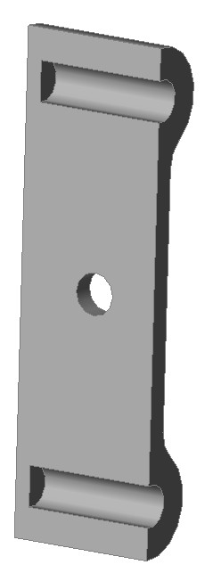
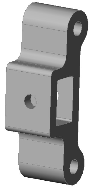
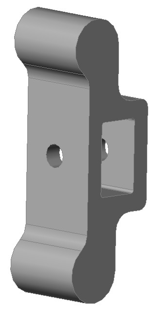
Here is the revision to the X-belt idler end:
And modifications to the Z-bearing clamps to locate the X-rods:
The center of the belt is 7mm offset from the center of the rods, and that's required to clear the Z-rod.

And modifications to the Z-bearing clamps to locate the X-rods:


The center of the belt is 7mm offset from the center of the rods, and that's required to clear the Z-rod.
|
Re: Help with cantilevered printer design April 18, 2014 03:18AM |
Registered: 10 years ago Posts: 1,381 |
Looks good, and you're fast!
After seeing your model of the clam shell version of the X axis distal bracket, I think it can be further simplified.
You might not need any bolts to secure it because with blind pockets for the rods to press up against, and a press fit, the bracket wont fall off with tension from the belt.
Print the holes under size to get a firm press fit onto the rods.
If you can't get a solid press fit, then I think you'll have problems with this concept when the belt reverses direction at high speed.
I would label this as an option that would have to be tested, and is not a sure thing.
Edited 1 time(s). Last edit at 04/18/2014 03:19AM by A2.
After seeing your model of the clam shell version of the X axis distal bracket, I think it can be further simplified.
You might not need any bolts to secure it because with blind pockets for the rods to press up against, and a press fit, the bracket wont fall off with tension from the belt.
Print the holes under size to get a firm press fit onto the rods.
If you can't get a solid press fit, then I think you'll have problems with this concept when the belt reverses direction at high speed.
I would label this as an option that would have to be tested, and is not a sure thing.


Edited 1 time(s). Last edit at 04/18/2014 03:19AM by A2.
|
Re: Help with cantilevered printer design April 23, 2014 06:19PM |
Registered: 10 years ago Posts: 22 |
Development has continued. Here are some pictures of the different Z-carriage parts I've printed out and test-fitted:
I changed the X-rod depth in the Z-carriage to 75mm to avoid making the carriage travel too small; I'm hoping that will be enough to hold it without sagging too badly. I also changed the way the Z-bearings are held in to zip-ties to simplify things.
Here's what the latest Z-carriage looks like (rod clamps not pictured):


Sorry, only registered users may post in this forum.