Printable diagonals
Posted by ErikDeBruijn
|
Printable diagonals July 26, 2008 07:28AM |
Registered: 16 years ago Posts: 293 |
I'd like to discuss experimental diagonals for the darwin design. The current 10 diagonals that are needed involve quite a lot of steel, weight and assembly time (as was just pointed out by hydraraptor here: [blog.reprap.org] )
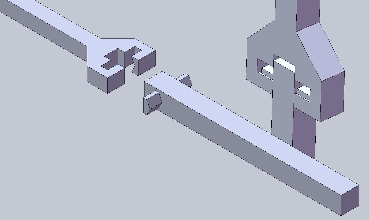
Together with a square frame, the brackets would only need to resist a pulling force. If we could (mostly) print these diagonals, this would result in a higher proportion of printable parts and lower material costs (in you use bulk industrial plastic, an not a prototyping service). There are 3 sketches I've made with decreasing amount of non-printable parts needed.
The first one will probably work, but the gain is perhaps not as big either.
V2 reduces the need for two more bolts, two nuts and four washers. It could have multiple places where it can lock together (more holes that the pins fit in).
Because it's made of two parts it will fit in the print volume... easily even, when printed diagonally as well.
What do you guys think?
Regards,
Erik de Bruijn
[Ultimaker.com] - [blog.erikdebruijn.nl]
Together with a square frame, the brackets would only need to resist a pulling force. If we could (mostly) print these diagonals, this would result in a higher proportion of printable parts and lower material costs (in you use bulk industrial plastic, an not a prototyping service). There are 3 sketches I've made with decreasing amount of non-printable parts needed.
The first one will probably work, but the gain is perhaps not as big either.

V2 reduces the need for two more bolts, two nuts and four washers. It could have multiple places where it can lock together (more holes that the pins fit in).

Because it's made of two parts it will fit in the print volume... easily even, when printed diagonally as well.
What do you guys think?
Regards,
Erik de Bruijn
[Ultimaker.com] - [blog.erikdebruijn.nl]
|
Re: Printable diagonals July 26, 2008 08:46AM |
Registered: 15 years ago Posts: 151 |
I like the Idea!
I think the design should be interchangeable with steel rods, so that people using a printing service can easily use steel rods instead of paying $1000 for a rod.
I have an Idea for V3, but it won't translate into words well so I'll post a pic when I reboot into windows later and start up SolidWorks.
-Leav
|
Re: Printable diagonals July 26, 2008 08:50AM |
Registered: 16 years ago Posts: 293 |
@ Leav: Cool, I'm interested!
Of course there are many variations possible. This was a concept to get the discussion started. The utterly cool thing is that Chris (hydraraptor) could print an STL we design to test the concept and to improve his RepRap.
Regards,
Erik de Bruijn
[Ultimaker.com] - [blog.erikdebruijn.nl]
Of course there are many variations possible. This was a concept to get the discussion started. The utterly cool thing is that Chris (hydraraptor) could print an STL we design to test the concept and to improve his RepRap.
Regards,
Erik de Bruijn
[Ultimaker.com] - [blog.erikdebruijn.nl]
|
Re: Printable diagonals July 26, 2008 10:08AM |
Registered: 15 years ago Posts: 151 |
here it is, the idea is to have the rod more resistant to sideways load. (that may cause rods to slip and separate.
This is just the general concept of using a groove really.
I'm sure that this particular setup can be improved greatly but the groove is key.
Not sure how you would tighten this. perhaps V1 is a better option after all
-Leav
Edited 1 time(s). Last edit at 07/26/2008 10:11AM by Leav.
This is just the general concept of using a groove really.
I'm sure that this particular setup can be improved greatly but the groove is key.
Not sure how you would tighten this. perhaps V1 is a better option after all
-Leav
Edited 1 time(s). Last edit at 07/26/2008 10:11AM by Leav.
|
Re: Printable diagonals July 26, 2008 10:38AM |
Admin Registered: 17 years ago Posts: 1,915 |
Eric. You need to ask Adrian for permission to use the builder's blog if you don't already have it. You've brought up an important issue. This should be on the blog, not the forums.
The whole subject of how you print parts to make a larger whole is one that needs a lot of discussion and thought.
-------------------------------------------------------
Hell, there are no rules here - we're trying to accomplish something.
Opportunity is missed by most people because it is dressed in overalls and looks like work.
Thomas A. Edison
|
Re: Printable diagonals July 26, 2008 11:09AM |
Registered: 16 years ago Posts: 361 |
Quote
Not sure how you would tighten this. perhaps V1 is a better option after all
I think adjustable tension is probably the killer here... I'm assuming you want fairly fine control over this so you can true up your darwin frame. The V3 doesn't really have this facility at all, and I'd be concerned that the V2's adjustabaility would be just too coarse.
I guess you'd need to ask someone who's set up a darwin already, really

Personally, I'm visualing something like a zip tie: [en.wikipedia.org] I'm rather assuming that we can't make something quite like a proper zip tie fastener, but it would be a terribly useful item to be able to make.
Each crossbeam part (for they would be identical, ideally) would have a partially serrated surface with teeth angled back towards the tie points. Two opposing beam parts places serrated sides together woudld bite. They'd be solid bars rather than flexible strips to make the whole thing a little more rigid.
The tricky bit then is the bit that holds them together. You want something firm enough that the beam can take a decent amount of tension without springing apart, yet you still want to be able to tighten the bits easily.
Something which can clamp the two crossbeams together should work... a C shaped clamp that slides on from the side, with a simple pin or clip to hold it shut would probably do, given that most of the force will be tension in the crossbeam. The clamp just needs to be able to stop a comparatively smaller lateral force from pushing the two beams apart.
So. Uh. I'm not going to try and ascii art this one. Does anyone feel I should try and make a proper diagram?
|
Re: Printable diagonals July 26, 2008 11:25AM |
Registered: 15 years ago Posts: 151 |
|
Re: Printable diagonals July 26, 2008 11:48AM |
Registered: 16 years ago Posts: 361 |
|
Re: Printable diagonals July 26, 2008 12:06PM |
Registered: 16 years ago Posts: 161 |
Leav Wrote:
-------------------------------------------------------
> I like the Idea!
> I think the design should be interchangeable with
> steel rods
> -Leav
This is slightly off topic, but you just reminded me of an idea i had a while back:
It would be good to develop some kind of 3d object file that could be customisable by the user with various different options:
e.g. the extruder could support several different motors with the mounting holes in different places, which could be chosen in software before printing.
It's probably not worth getting into this yet though as there are a lot more important things to do.
|
Re: Printable diagonals July 26, 2008 12:17PM |
Registered: 16 years ago Posts: 293 |
greenarrow: this has two advantages, one is quantitative: any reprapper could create stuff somewhat more quickly. The qualitative thing is: it puts end-users in control. Before, no end user could be asked to have influence over CAD.
If we have some ideas I'll post a summary on Builders.reprap.org for sure. Hopefully I can post it with something tried out by hydraraptor
With the ridges, you can use 3 sides of the beam at different offsets (resulting in different tensions). Using a single bolt to have an adjustable tension would also work.
Making compound parts that could be replacements for the structural parts of a RepRap is important, but I chose to discuss this first, since it is an easy start and to get some experience with it. I think we could print other (modular) structural parts with ribs for extra strength as well, but we have to design those first and they will impact the Darwin 1.0 design to a greater degree. I think for Mendel it would be a nice achievement to replace much more of the structural steel.
Regards,
Erik de Bruijn
[Ultimaker.com] - [blog.erikdebruijn.nl]
|
Re: Printable diagonals July 26, 2008 03:32PM |
Registered: 16 years ago Posts: 213 |
I like Leav's tongue and groove option, and just suggest a V3.1 option, which would be V3 with straight teeth that snugly fit instead of of wedge teeth with a gap. It would be a tighter fit, but would provide compressive stiffness as well. To keep it from sliding out you could make a ring to go over the connection section.
Ru,
Now that Nophead has shown that the filament can span bridges, it should be possible to make a large zip tie. Would someone like to design one?
Edited 1 time(s). Last edit at 07/26/2008 03:38PM by Enrique.
Ru,
Now that Nophead has shown that the filament can span bridges, it should be possible to make a large zip tie. Would someone like to design one?
Edited 1 time(s). Last edit at 07/26/2008 03:38PM by Enrique.
|
Re: Printable diagonals July 26, 2008 03:49PM |
Admin Registered: 17 years ago Posts: 7,879 |
Eric,
Yes I will endeavor to try things out for people, remember HydraRaptor only has a build area about 130 by 140mm.
The studding bars are only about
[www.hydraraptor.blogspot.com]
Yes I will endeavor to try things out for people, remember HydraRaptor only has a build area about 130 by 140mm.
The studding bars are only about
[www.hydraraptor.blogspot.com]
|
Re: Printable diagonals July 26, 2008 04:08PM |
Registered: 16 years ago Posts: 293 |
Funny, steel cable was my first thought. I may be most practical, but you should take into account the time to look for different parts in a hardware store that is also part of the cost. Perhaps the rods are even better in this respect than steel cable, because it's a new kind of part. The idea of a ubiquitous/homogenous set of parts that complement the homogenous set of plastic parts is a strong one.
Then again, it is quite a heavy machine now. I can barely carry it to demo it.
Regards,
Erik de Bruijn
[Ultimaker.com] - [blog.erikdebruijn.nl]
Then again, it is quite a heavy machine now. I can barely carry it to demo it.
Regards,
Erik de Bruijn
[Ultimaker.com] - [blog.erikdebruijn.nl]
|
Re: Printable diagonals July 26, 2008 06:19PM |
Admin Registered: 17 years ago Posts: 7,879 |
Yes it is very heavy, especially my version with 4 z-axis motors and a fan-less power supply.
The only other use of the M8 studding is the z-axis. My experiment with four tiny steppers failed with M8. Perhaps we could replace all the M8 with M4 and kill two or three birds with one stone. Cheaper, lighter, even smaller brackets, still only one type of studding. We would probably have to move the motors to the top as Forrest pointed out so the studding is always in extension, but that would have the benefit of increasing the z-travel.
Replacing the MDF bed with a composite laminate would also make it lighter, but a bit more exotic. 3MM HDPE laminated with AL is very flat, strong and light.
[www.hydraraptor.blogspot.com]
|
Re: Printable diagonals July 26, 2008 08:15PM |
Registered: 16 years ago Posts: 174 |
If you just need to supply some sort of adjustable tension why not use nylon cord?
It's fairly cheap, $3.95 for 50 ft, with 300lbs load capacity:
[www.rei.com]
It's fairly cheap, $3.95 for 50 ft, with 300lbs load capacity:
[www.rei.com]
|
Re: Printable diagonals July 26, 2008 08:20PM |
Admin Registered: 17 years ago Posts: 7,879 |
We need something that will not stretch in order to make the frame rigid, tension does not help, other than you need some initial tension to take up the slack.
[www.hydraraptor.blogspot.com]
[www.hydraraptor.blogspot.com]
|
Re: Printable diagonals July 27, 2008 02:16AM |
Registered: 17 years ago Posts: 550 |
pe cord (Dyneema) doesn't stretch, that's why it's used for sailing riggs, bulletproof vests and some other stuff.
[www.dsm.com]
It withstand 15times the force steelwire would and even 40% more than aramid.
I think, that would be my first choice so far
'sid
[www.dsm.com]
It withstand 15times the force steelwire would and even 40% more than aramid.
I think, that would be my first choice so far
'sid
|
Re: Printable diagonals July 27, 2008 05:28AM |
Registered: 16 years ago Posts: 361 |
Quote
pe cord (Dyneema) doesn't stretch
From [en.wikipedia.org] (but a brief googling will get you a more reliable reference!)
Quote
Under tensile load, UHMWPE will deform continually as long as the stress is present - an effect called creep.
So you might not want it as a continuous load bearer... though it isn't like a reprap is going to put it under serious strain 24/7
|
Re: Printable diagonals July 27, 2008 05:00PM |
Registered: 15 years ago Posts: 83 |
...Sorry to jump in when everyone is talking about coord and cable, but I have a question.
Why, again, do we only care about pulling forces here? As two opposite faces of a square move to make a parallelogram, one diagonal expands (pulling force) and one contracts (compression). So, it seems that if we are going to talk about pulling forces, we could equally (and symmetrically) talk about compression forces.
Granted, if we agree to always tighten the diagonals such that there is always a pulling force, we could focus on things that can withstand only that force. We could also agree to always put a little more diagonal in than the frame is comfortable with, causing there to aways be compressional forces instead.
I don't know.. Our basic assumption on this topic seemed arbitrary. Feel free to set me right. I am no mechanical engineer.
Have a great day!
|
Re: Printable diagonals July 27, 2008 05:12PM |
Admin Registered: 17 years ago Posts: 7,879 |
If the diagonal being pulled does not stretch then the other one will not be able to compress even if it is weak in compression.
The M8 studding is weaker in compression because it can bow under moderate force but to do that the opposite one would have to stretch which requires massive force.
[www.hydraraptor.blogspot.com]
The M8 studding is weaker in compression because it can bow under moderate force but to do that the opposite one would have to stretch which requires massive force.
[www.hydraraptor.blogspot.com]
|
Re: Printable diagonals July 27, 2008 06:24PM |
Registered: 15 years ago Posts: 83 |
I was thinking about the original posting, and the need for some sort of coupler to join the two half-diagonal pieces came to mind. Check out the following thread for discussion on a modular connection design that could be used throughout the repRap design:
[forums.reprap.org]
[forums.reprap.org]
|
Re: Printable diagonals July 27, 2008 08:45PM |
Registered: 15 years ago Posts: 83 |
nophead Wrote:
-------------------------------------------------------
> If the diagonal being pulled does not stretch then
> the other one will not be able to compress even if
> it is weak in compression.
>
> The M8 studding is weaker in compression because
> it can bow under moderate force but to do that the
> opposite one would have to stretch which requires
> massive force.
That makes sense... Thanks!
|
Re: Printable diagonals July 27, 2008 09:05PM |
Registered: 16 years ago Posts: 370 |
Ru Wrote:
-------------------------------------------------------
> pe cord (Dyneema) doesn't stretch
>
> From [en.wikipedia.org] (but a
> brief googling will get you a more reliable
> reference!)
>
> Under tensile load, UHMWPE will deform continually
> as long as the stress is present - an effect
> called creep.
>
> So you might not want it as a continuous load
> bearer... though it isn't like a reprap is going
> to put it under serious strain 24/7
Perhaps not serious strain, but definitely 24/7. This is a constant load application, because it remains taut even when the RepRap isn't in use. A cord that has a tendency to go slack may not be the best solution...
|
Re: Printable diagonals August 17, 2008 12:15AM |
Registered: 16 years ago Posts: 56 |
Well what if for the steel cable option you used eye bolts. That why you could easy test it on a current Darwin and there would be no need to change the diagonal brackets. Think of it as taking a normal threaded diagonal and chopping out the middle and replacing it with cable. The cable would be looped though the eye bolts and clamped with wire clamps. [www.westcoastnetting.com] . The only advantages to this over the threaded rod I can see is weight and possibly it might be easier for people to get metric eye bolts at the big box stores rather than trying to find metric threaded rod longer than 10 cm.
Sorry, only registered users may post in this forum.