SoM Y axis rebuild
Posted by the_digital_dentist
|
SoM Y axis rebuild November 20, 2018 01:16PM |
Registered: 11 years ago Posts: 5,780 |
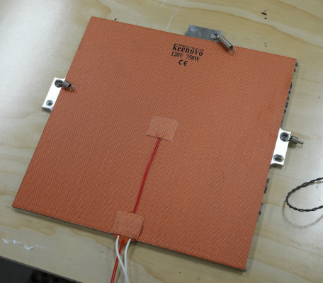
I took the ball screw out of SoM's Y axis to convert it to belt drive. While I was at it I cut a new bed plate from 1/4" MIC6 plate and designed new support structure using a kinematic mount similar to the one in UMMD. I used the same 750W, line powered heater I used in UMMD which should get the plate up to ABS print temperature in about 3 minutes.
The new bed plate is the same size as the heater- 300x300 mm, with ears for the leveling screws and hold-down springs. I'll be attaching a TCO to the heater with high temperature silicone to prevent a disaster if the SSR that switches power to the heater fails.
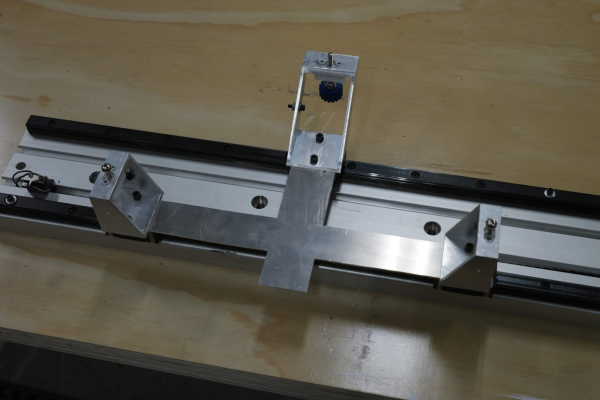
The original 1/4" thick carriage plate was mounted on top of the bed supports which put it very close to the bed heater. This time I opted to use 2.5 mm aluminum and put the carriage plate on the bearing blocks, moving it far from the bed heater.
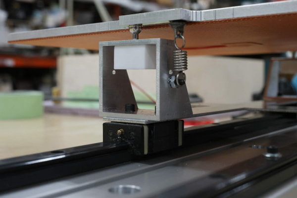
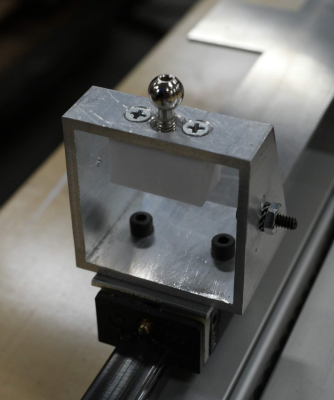
The leveling screws are threaded into/through Teflon blocks that won't soften or melt when the screws get hot. The supports are made from 2" square aluminum tubing. Springs hold the bed plate down onto the leveling screw heads. It remains to be seen whether the spring force will cause the plate to flex enough to affect printing.
The holes for the leveling screws in the aluminum tube supports are oversized so the screws don't touch the aluminum.
The belt clamp will probably attach to the carriage plate. I haven't settled on the final design for the clamp yet, but it will probably be a self-locking type that folds the ends of the belt over on themselves.
Edited 1 time(s). Last edit at 11/20/2018 01:24PM by the_digital_dentist.
Ultra MegaMax Dominator 3D printer: [drmrehorst.blogspot.com]
|
Re: SoM Y axis rebuild November 26, 2018 01:25PM |
Registered: 5 years ago Posts: 61 |
Have you looked at Kinematic couplings? It might be interesting to try spacing the three mounts around a PCD so the slots all point inwards. Currently I think you're slightly over-constraining the bed still so it may be beneficial to switch to three sets of rollers / grooves rather than what you have at the moment. Edit: Nah you're good.
Edited 1 time(s). Last edit at 11/26/2018 03:13PM by Ed3D.
Edited 1 time(s). Last edit at 11/26/2018 03:13PM by Ed3D.
|
Re: SoM Y axis rebuild November 26, 2018 01:33PM |
Registered: 11 years ago Posts: 5,780 |
You're referring to the Maxwell type kinematic mount. Those are effective, too, but harder (for me) to make. You have to be able to mill the slots in the plate at accurate 120 degree angles.
What I made is a Kelvin type kinematic mount. It's a lot easier to make because there's only one slot and it runs parallel to the mill's X axis.
How is the bed overconstrained?
Ultra MegaMax Dominator 3D printer: [drmrehorst.blogspot.com]
What I made is a Kelvin type kinematic mount. It's a lot easier to make because there's only one slot and it runs parallel to the mill's X axis.
How is the bed overconstrained?
Ultra MegaMax Dominator 3D printer: [drmrehorst.blogspot.com]
|
Re: SoM Y axis rebuild November 26, 2018 01:51PM |
Registered: 10 years ago Posts: 14,672 |
Quote
the_digital_dentist
You're referring to the Maxwell type kinematic mount. Those are effective, too, but harder (for me) to make. You have to be able to mill the slots in the plate at accurate 120 degree angles.
If the angles are not exactly 120 degrees then I believe the Maxwell mount will still work, however there will be a slight rotation of the bed when the temperature differential changes. I don't think this would matter any more than the slight linear shift that you get using a Kelvin kinematic coupling.
Large delta printer [miscsolutions.wordpress.com], E3D tool changer, Robotdigg SCARA printer, Crane Quad and Ormerod
Disclosure: I design Duet electronics and work on RepRapFirmware, [duet3d.com].
|
Re: SoM Y axis rebuild November 26, 2018 03:18PM |
Registered: 5 years ago Posts: 61 |
Quote
dc42
Quote
the_digital_dentist
You're referring to the Maxwell type kinematic mount. Those are effective, too, but harder (for me) to make. You have to be able to mill the slots in the plate at accurate 120 degree angles.
If the angles are not exactly 120 degrees then I believe the Maxwell mount will still work, however there will be a slight rotation of the bed when the temperature differential changes. I don't think this would matter any more than the slight linear shift that you get using a Kelvin kinematic coupling.
You're absolutely right I simply didn't look hard enough
 Im so used to seeing Maxwell type mounts I just defaulted to that!
 There are a few methods to make the maxwell type mount a little easier to manufacture. You can use Rollers in place of the V which is much easier or you can use V slot inserts.
It should still work if you move away from 120 deg angles but you might be right about twisting.
I really like this - nice work. Have you considered spacing the support points out accross the bed a bit more?
Edited 1 time(s). Last edit at 11/26/2018 03:27PM by Ed3D.
Sorry, only registered users may post in this forum.


