Possible Extruder Design?
Posted by pingiscoolest
|
Possible Extruder Design? April 15, 2009 11:40PM |
Registered: 15 years ago Posts: 62 |
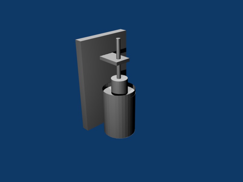
This seems like a good design for an extruder to me, I have attached the blender file, and the render as a JPG, it seems to me this could extrude a wide range of materials, including plastic pellets, wax (support material?), paste, or almost anythng that can be forced through a hole heated or not with a little pressure. The idea is that the largest cylinder is a piece of 4 inch metal pipe wrapped in nicrome wire at the bottom with an endcap with a hole drilled in it the correct size (i dont know what that is). The circle near the middle of the pipe is a piece of sheet metal cut to four inches in diameter with a hole saw or other tool (lathe?) and small holes in it drilled so air may escape but the surface tension of the material being extruded keeps it in. the smaller cylinder is a motor of about 100 rpm and a large amount of torque (again dont know exact amount) the smallest cylinder is a 1/4" 20 threaded rod attached to the shaft of the motor. The large rectangular prism is a piece of 1"x6" about 7" tall and the smaller prism is a block of wood containing a captive nut. the threaded rod runs through this nut and as it turns it forces the motor and therefore the circular sheet metal down which drives the material to be extruded through the drilled hole.
Comments? Questions? Would it work? Constructive criticism ?
?
Comments? Questions? Would it work? Constructive criticism
?
|
Re: Possible Extruder Design? April 16, 2009 02:22AM |
Registered: 15 years ago Posts: 186 |
|
Re: Possible Extruder Design? April 16, 2009 07:45AM |
Registered: 15 years ago Posts: 34 |
Interesting - I've also been thinking of a design that has a pool of molten material rather than melting it 'just in time', mainly to allow the use of pellet feedstock. The problem is metering the material - the amount of material between the piston and the needle means it will be quite compressible (particularly if pellets are used) and that means it would be difficult to accurately meter the flow using the motor.
However, if you have a valve on the needle and a pressure sensor on the piston you should be able to use the motor to maintain an even pressure and the valve to meter the flow. Or possibly just have an on/off valve and vary the pressure to change the flow rate.
I also think you'll need a thermal break to limit the heated volume to the bottom of the cylinder otherwise the cylinder will just act as a heatsink.
|
Re: Possible Extruder Design? April 16, 2009 09:15AM |
Registered: 15 years ago Posts: 62 |
Well as for the surface tension that might require some experimentation but air does not require large holes at all and maybe it could escape just through the small gap that would probably be inevitable between the circular plate and the pipe. If holes were needed I am not sure how small they would need to be but if some material escaped as long as it needed to be heated to flow then it might just harden and stop any more material from escaping.
_______________________________________________________________________________________________________
Yes my Avatar is My RepStrap.....Isn't it pretty
For the latest Updates check my main site [www.repstrap.weebly.com] or my blog [www.pingiscoolest.blogspot.com].
_______________________________________________________________________________________________________
Yes my Avatar is My RepStrap.....Isn't it pretty
For the latest Updates check my main site [www.repstrap.weebly.com] or my blog [www.pingiscoolest.blogspot.com].
|
Re: Possible Extruder Design? April 16, 2009 04:45PM |
Registered: 15 years ago Posts: 186 |
Hi there - welcome to the RepRap world.
To post links try including the http : // for example:
[www.pingiscoolest.blogspot.com]
---
Reprapping blog and other rants: [renoirsrants.blogspot.com]
My Reprap: [sites.google.com]
To post links try including the http : // for example:
[www.pingiscoolest.blogspot.com]
---
Reprapping blog and other rants: [renoirsrants.blogspot.com]
My Reprap: [sites.google.com]
|
Re: Possible Extruder Design? April 16, 2009 08:05PM |
Registered: 15 years ago Posts: 62 |
hey that worked.. I think... Thanks David!
_______________________________________________________________________________________________________
Yes my Avatar is My RepStrap.....Isn't it pretty
For the latest Updates check my main site [www.repstrap.weebly.com] or my blog [www.pingiscoolest.blogspot.com].
_______________________________________________________________________________________________________
Yes my Avatar is My RepStrap.....Isn't it pretty
For the latest Updates check my main site [www.repstrap.weebly.com] or my blog [www.pingiscoolest.blogspot.com].
|
Re: Possible Extruder Design? April 16, 2009 08:43PM |
Registered: 15 years ago Posts: 62 |
Oh hey David I recognize your avatar, I use the full size pic in a RepRap calendar for a computer class, hope you dont mind .
_______________________________________________________________________________________________________
Yes my Avatar is My RepStrap.....Isn't it pretty
For the latest Updates check my main site [www.repstrap.weebly.com] or my blog [www.pingiscoolest.blogspot.com].
._______________________________________________________________________________________________________
Yes my Avatar is My RepStrap.....Isn't it pretty
For the latest Updates check my main site [www.repstrap.weebly.com] or my blog [www.pingiscoolest.blogspot.com].
|
Re: Possible Extruder Design? April 17, 2009 02:19AM |
Registered: 15 years ago Posts: 186 |
I don't mind :-)
Happy to help.
re: extruder design
The best way to find out the problems is to prototype it. It doesn't have to be perfect, use whatever you have to hand: lego, cardboard, nuts/bolts, wood, plastic, sellotape, whatever. Even assembling a paper cutout will give you a much clearer understanding of the design, and things often look different on paper/computer, when you can see the real sizes and how to assemble and build it.
Next step is a method (partial working) prototype. If you can use metal/plastic - great, otherwise use whatever might be strong enough to have a go (lego, etc). If you're protoyping the extruder, you could simulate molten plastic with plasticine/clay/a thick mixture of cornflour and water.
This can give you a good idea of whether it actually works and what problems might be. It doesn't need to be the whole thing, or the right sizes, or whatever - just prove that the method works.
e.g. you can prototype heaters by applying a bit of current to a well held wire/resistor or a partial build and check temp with a kitchen thermometer (or touch it with an old candle to see if the wax melts, or drip a single drip of water to see if it boils). Be careful, the heaters often get too hot too quick to touch with your fingers.
If you can, building a fully working prototype yourself gives the best results. You find and learn far more, but does take a lot of effort.
It's actually pretty hard to criticise a design: unless you're an expert, or even if you've done the same thing before, it's hard to say whether it might work or not - and even the 'experts' can be wrong sometimes. I found building it is the only way :-)
---
Reprapping blog and other rants: [renoirsrants.blogspot.com]
My Reprap: [sites.google.com]
|
Re: Possible Extruder Design? April 17, 2009 09:14AM |
Registered: 15 years ago Posts: 62 |
well I guess I will start to build a prototype . probably will be made of pvc pipe and wood, but that will have to wait till tonight. I will probably need some nicrome wire for almost any extruder I make so I will go ahead and order that soon. And since I dont have any plastic to extrude, I guess my prototype has no need to be heated.
Thanks for the advice!
_______________________________________________________________________________________________________
Yes my Avatar is My RepStrap.....Isn't it pretty
For the latest Updates check my main site [www.repstrap.weebly.com] or my blog [www.pingiscoolest.blogspot.com].
. probably will be made of pvc pipe and wood, but that will have to wait till tonight. I will probably need some nicrome wire for almost any extruder I make so I will go ahead and order that soon. And since I dont have any plastic to extrude, I guess my prototype has no need to be heated.Thanks for the advice!
_______________________________________________________________________________________________________
Yes my Avatar is My RepStrap.....Isn't it pretty
For the latest Updates check my main site [www.repstrap.weebly.com] or my blog [www.pingiscoolest.blogspot.com].
|
Re: Possible Extruder Design? April 17, 2009 12:21PM |
Registered: 15 years ago Posts: 186 |
Nophead and I have both used Wirewound resistors (http://renoirsrants.blogspot.com/2009/03/new-parts-arrived.html) as an alternative to Nichrome. It can also be found in hairdriers and electric heaters, if you can find an old one (it might be easier to get hold of).
Anything that is touching melted plastic (ABS) needs to be SAFE at 240C. This means PTFE, PEEK, and metal are OK: wood is not. Also be aware that even glue and tape (stuff like superglue can degrade at 150C) need to be fireproof.
If you're using CAPA (polymorph) you have a wider range of materials.
Anything that is touching melted plastic (ABS) needs to be SAFE at 240C. This means PTFE, PEEK, and metal are OK: wood is not. Also be aware that even glue and tape (stuff like superglue can degrade at 150C) need to be fireproof.
If you're using CAPA (polymorph) you have a wider range of materials.
|
Re: Possible Extruder Design? April 17, 2009 06:52PM |
Registered: 15 years ago Posts: 62 |
well I was going to use fireplace cement to hold everything together so that shouldn't be a problem. I guess I will be using metal for the top plate I happen to have 2 hairdryers with broken motors so maybe I can use that. Wow 240C is really hot! I guess I was thinking 240F when I read everything else that mentioned extruder temperature. Big difference!! About 270F difference! anyway I made a quick prototype out of duct tape pvc pipe and wood. It was a lot shorter and fatter than I expected but it should work fine though my duct tape wasnt water proof (yes I know water isnt a good substitute for ABS but I am not sure how I could possibly extrude clay maybe I didnt understand you right). How would I go about determining what part is the wireround resistor. When I opened the hairdryer all I found was what looked like a metal coated plate of made of something nonconductive. I also found a few diodes and another part that I could not identify. I googled the part number and it is a Thermal Fuse. Whaere would I look to find this wireround resistor? does my hair dryer maybe have a different heating element?
|
Re: Possible Extruder Design? April 18, 2009 05:27AM |
Registered: 15 years ago Posts: 186 |
Normally, hairdriers have a series or mesh of nichrome or resistor wire along the body of the hairdrier: wirewound resistors are a high-power version of normal electronics resistors, available from electronics shops, etc ( sorry for the confusion!)
I use fireplace cement for extruder elements (it works well) but I've just found [www.krakentape.com] which I'm currently trying out.
240C is for ABS (Note that's also a similar temperature to a soldering iron)
110C-ish I think is OK for polymorph (CAPA) - check the reprap wiki for other plastics.
Suggestion of clay or plasticine is because even 'molten' ABS is not very liquid: it's more like a paste, or 'silly putty' - it needs to be squeezed through a nozzle. winding the filament down is a bit like pushing a rod (solid plastic) into the soft melted plastic and forcing it through the nozzle.
If your design can push plasticine through, it should be OK for ABS.
|
Re: Possible Extruder Design? April 18, 2009 02:37PM |
Registered: 15 years ago Posts: 62 |
Wow another thing I didn't know about ABS. I guess I should have looked into this a little more, I will be needing more torque than I expected. Thanks for all the info I will continue working on this, if it doesn't work as an ABS extruder (I am reluctant to use CAPA it is expensive, almost £20 ($30) a pound almost 4 times what ABS cost from makerbot) then maybe it will make a good wax or support material extruder... we'll see .
BTW I will be following your blog looks intereting
.BTW I will be following your blog looks intereting
|
Re: Possible Extruder Design? April 18, 2009 06:35PM |
Registered: 15 years ago Posts: 186 |
CAPA is also non-liquid, and like soft paste.
There's some excellent work by Nophead on how much force is needed and how much the current extruders use, along with the current drive systems:
[hydraraptor.blogspot.com]
Average results look like it takes at least 5kg (50 N) applied to a 3mm rod to force melted ABS through a 0.5mm nozzle. So, if you like, turning the extruder the other way up, it should be able to lift at least 5 bags of sugar off the floor - using the ABS rod. Normally, the problem is getting enough grip on the plastic (it just slides out).
I've also been playing with chocolate as an extrusion material - not as useful, but more fun and less dangerous! Might be an interesting prototyping test material, as it's liquid and seems to extrude OK.
[renoirsrants.blogspot.com]
:-)
---
Reprapping blog and other rants: [renoirsrants.blogspot.com]
My Reprap: [sites.google.com]
|
Re: Possible Extruder Design? April 19, 2009 01:37AM |
Registered: 16 years ago Posts: 536 |
Dave has a good point - the internal pressure applied to the ABS is quite high to get it to extrude nicely on our current extruders. If we assume 50 N on a 3 mm diameter filament, that's about 7 MPa of pressure (about 1000 psi). I'm neglecting friction, and a lot of other things too, but that's a lot of pressure! If your big extruder has an internal diameter of, say, 3.5 inches, that's about 9 square inches of surface area for your piston, which means you'll have to push on it with 9000 lbs of force. That would be tough to do!
Forrest mentioned an estimated extruder pressure of 17 to 18 bar in a previous post, which would be only 250 psi, but that's still about 2000 lbs of force on a 3.5 inch barrel. It gets up there quickly!
This sort of thing would be great for making filament though - if you could get it to extrude reliably, you could extruder filament onto a spool, and have that fed into one or more repraps. That way you wouldn't have to swing around a giant, heavy extruder head as your print your part.
Wade
|
Re: Possible Extruder Design? April 19, 2009 02:39PM |
Registered: 15 years ago Posts: 62 |
Yes that is a good Idea Wade. I think Forrest had the same idea in one of his posts. His idea if I remember correctly was to use an air compressor to get the right amount of pressure though I dont know of an aircompressor that can output 250 PSI! I am not sure how to do the math here do you think this motor could handle it? [store.kysanelectronics.com] I am not sure how to convert between the torque of 2.853 kg/cm and the force it could output on the piston. Maybe someone could tell me if this motor has even close to the right amount of torque.
|
Re: Possible Extruder Design? April 19, 2009 03:23PM |
Registered: 15 years ago Posts: 88 |
Torque = Force * radius. (so it's actually kg*cm, not kg/cm). 1kg*cm = 0.867961662 lb*in, so the motor has 2.47629462 pound in of torque available. That means that if the "shaft" of the motor (ie including the drive gear) were 1 inch, if could supply 2.476 pounds of force. That would be enough force to build 250PSI on a piston with just under 1/10 sq. inch cross section. With an additional 10:1 gear reduction you could go almost to a 1 sq. inch cross section.
|
Re: Possible Extruder Design? April 20, 2009 09:06AM |
Registered: 15 years ago Posts: 62 |
|
Re: Possible Extruder Design? April 20, 2009 11:01AM |
Registered: 15 years ago Posts: 88 |
Ack! No, I did not notice the part with the 1/4-20 rod. (that'll teach me to speedread the forums XD).
As far as torque/force is concerned, I think that it is like any other gear reduction. That makes it a 20:1 reducer. I'm not entirely certain what figure is used for initial radius though. If it's 1/4", you have an initial torque of 9.90517848. A 20:1 reduction would then give a force of 198.10357 lbs. 198 lbs/250psi = 0.792 sq. inch piston.
HOWEVER. I've never tried to compute forces on a threaded rod like this before. This may or may not be the correct method.
|
Re: Possible Extruder Design? April 20, 2009 09:29PM |
Registered: 15 years ago Posts: 62 |
|
Re: Possible Extruder Design? April 21, 2009 01:04AM |
Registered: 15 years ago Posts: 88 |
Actually.. I just realized why I felt odd about that conversion. It's wrong. A 1/4-20 threaded rod is 20 threads per INCH. One revolution is therefore 1/20 of an inch of movement. If your initial diameter is 1/4", your initial radius is 1/8" of an inch. Your circumference is 2pi*r, so 0.785398163". 1/20 of an inch is .05" in decimals. So your reduction is from .7854" to .05", which gives a figure of around 15.6:1 reduction, not 20:1. Assuming I was right about it being the same as any other gear reduction, you're looking at 154.5 lbs of force, so closer to .618 sq. inches cross section at 250 psi. Sorry.
|
Re: Possible Extruder Design? April 21, 2009 10:52PM |
Registered: 15 years ago Posts: 62 |
No Problem thanks for the help!
_______________________________________________________________________________________________________
Yes my Avatar is My RepStrap.....Isn't it pretty
For the latest Updates check my main site [www.repstrap.weebly.com] or my blog [www.pingiscoolest.blogspot.com].
_______________________________________________________________________________________________________
Yes my Avatar is My RepStrap.....Isn't it pretty
For the latest Updates check my main site [www.repstrap.weebly.com] or my blog [www.pingiscoolest.blogspot.com].
Sorry, only registered users may post in this forum.